AFRISO TankControl 10 Operating Instructions Manual
Hydrostatic level indicator for fuel oil, diesel fuel and water
Hide thumbs
Also See for TankControl 10:
- Operating instructions manual (147 pages) ,
- Operating instructions manual (197 pages)
Table of Contents
Advertisement
Quick Links
Operating instructions
Hydrostatic level indicator for fuel oil, diesel fuel
and water
TankControl 10
+
Read instructions before using product!
+
Observe all safety information!
+
Keep instructions for future use!
10.2016 0
854.001.0739
Mess-, Regel- und
Überwachungsgeräte
für Haustechnik,
Industrie und Umweltschutz
Lindenstraße 20
74363 Güglingen
Telefon +49 7135 102-0
Service +49 7135-102-211
Telefax +49 7135-102-147
info@afriso.de
www.afriso.com
Advertisement
Table of Contents

Related Manuals for AFRISO TankControl 10


Summary of Contents for AFRISO TankControl 10
-
Page 1: Operating Instructions
Telefon +49 7135 102-0 Service +49 7135-102-211 Telefax +49 7135-102-147 info@afriso.de www.afriso.com Operating instructions Hydrostatic level indicator for fuel oil, diesel fuel and water TankControl 10 Read instructions before using product! Observe all safety information! Keep instructions for future use! 10.2016 0 854.001.0739... -
Page 2: Table Of Contents
Mounting additional submersible probe at the tank (optionally available) ....................23 Mounting the floating probe (optionally available)........25 Commissioning ...................... 26 Password ....................26 Setting time and date ................. 27 Setting the tank data .................. 28 Setting the alarms ..................31 TankControl 10... - Page 3 Troubleshooting ..................... 41 10 Decommissioning, disposal ................... 41 11 Spare parts and accessories ................. 41 12 Warranty ........................ 42 13 Copyright ....................... 42 14 Customer satisfaction .................... 42 15 Addresses ......................42 16 Enabling a retrofitted probe ................... 43 TankControl 10...
-
Page 4: This Instruction Manual
WARNING Possibly imminent danger! Failure to observe the information may result in death or severe injuries. CAUTION Dangerous situation! Failure to observe the information may result in minor or severe injuries as well as damage to property. TankControl 10... -
Page 5: Safety
Safety Safety Intended use The hydrostatic level indicator TankControl 10 may only be used to measure the level of low-viscosity, non-adhesive liquids: • Fuel oil EL as per DIN 51603-1 • Fuel oil L as per DIN 51603-2 • Diesel fuel as per EN 590 •... -
Page 6: Staff Qualification
The manufacturer or the sales company shall not be liable for damage whatsoever resulting from any use other than the use explicitly permitted in this instruction manual. The manufacturer shall not be liable for misprints. TankControl 10... -
Page 7: Product Description
Product description Product description Scope of delivery Fig. 1: Scope of delivery TankControl 10 Basic With second submersible With floating probe (ZS) probe (ZT) Control unit with probe cable 1 x universal submersi- 2 x universal submersible 1 x universal submersible... -
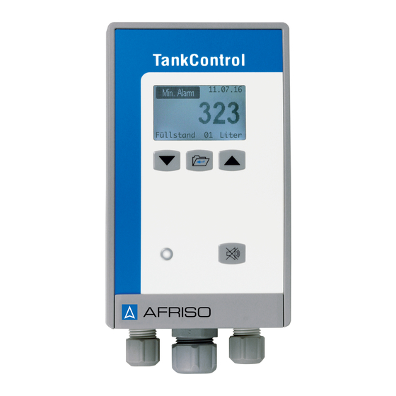
Page 8: Properties
Product description Properties TankControl 10 consists of a control unit with graphical display and a submersible probe with integrated pressure measuring cell. The level can be displayed in litres, cubic metres, percent or liquid level in mil- limetres. When the level falls below or exceeds an adjustable mini- mum or maximum value, the control unit triggers visual and, if de- sired, audible (can be acknowledged) alarms. -
Page 9: Application Example
Product description Application example Fig. 2: Application example 10 Key functions Function Scroll down/left. Scroll up/right. Display main menu. Select and confirm. Acknowledge button: Switch off buzzer during an alarm condition and display the alarm acknowledgement menu. TankControl 10... -
Page 10: Overview Of The Signals
Unit of measure- ment Number of probe Measured variable Alarm message Fig. 3: Indication of liquid level for submersible probe Date Symbol (relay) Number of probe Alarm level Alarm message Fig. 4: Status indication for floating probe TankControl 10... - Page 11 (with second submersible probe ZT) Floating probe alarm (with floating probe ZS) Menu Menu title Menu item Display Meaning Save the changed value Save Back to previous menu without saving <Back> Highlight the selected menu item TankControl 10...
-
Page 12: Overview Of The Menu Structure
Product description Overview of the menu structure TankControl 10... -
Page 13: Overview Of The Menu Structure (With Second Submersible Probe Zt)
Product description Overview of the menu structure (with second submersible probe ZT) TankControl 10... -
Page 14: Overview Of The Menu Structure (With Floating Probe Zs)
Product description Overview of the menu structure (with floating probe ZS) TankControl 10... -
Page 15: Technical Specifications
Value General specifications Dimensions (Ø x L) 24 x 53 mm Weight 415 g Length of probe cable Pressure range 0-400 mbar ≤ ± 0.5 % FSO, IEC 60770 Accuracy* ≤ ± 0.3 % FSO, 10°K Temperature error TankControl 10... - Page 16 Max. length 50 m (shielded) Resistance Water, oils Probe voltage Max. 17 V, AC Material Housing Polypropylene Probe cable Ölflex 2 x 0.5 mm² Operating temperature range Medium -5 °C to +50 °C Storage -10 °C to +60 °C TankControl 10...
-
Page 17: Approvals, Tests And Conformities
Cable glands at control unit Cable gland Cable diameter 4.0-8.8 mm 8.0-12.5 mm Approvals, tests and conformities TankControl 10 complies with the EMC Directive (2014/30/EU) and the Low Voltage Directive (2014/35/EU). Transport and storage CAUTION Damage to the product due to improper transport. ... -
Page 18: Mounting
The enclosed moisture-proof junction box is not suitable for out- door applications. Use the outdoor junction box for outdoor ap- plications, see chapter 11, page 41. Mounting the control unit Open the control unit. TankControl 10... - Page 19 Route the cable of the control unit into the junction box. Push the cable gland required for the tank (cable gland kit or mounting kit, see chapter 6.6, page 23) onto the cable of the submersible probe; verify correct orientation. TankControl 10...
- Page 20 Sealing the junction box in such a way that it is airtight also causes incorrect measurements. Close the junction box in such a way that it is not completely air- tight. Connect the unit electrically, see chapter 6.3, page 21. Close the control unit. TankControl 10...
-
Page 21: Electrical Connection
Yellow-green to terminal "Schirm" (shield), green to terminal "Signal", brown to terminal "AGND" and white to terminal "Vcc". An additional submersible probe must be enabled via the soft- ware at the control unit, see chapter 16, page 43. TankControl 10... -
Page 22: Zero Correction Of The Submersible Probe
The submersible probe and the control unit are connected. Mains voltage is connected and on. Set the current liquid level to "000000 mm" see fig. 12, page 29. You have now set the zero point of the probe. TankControl 10... -
Page 23: Mounting The Submersible Probe
The differential alarm of the second submersible probe is used to de- tect different liquid levels in communicating tanks. In the case of mul- tiple tanks, the first submersible probe should be installed in the first tank, the second submersible probe in the last tank. TankControl 10... - Page 24 (PG 9) Reducer G1½ - G1 Reducer G2 – G1½ Fig. 7: Mounting to tank with cable gland kit Tighten the cable gland so that the cable can no longer be moved and that the connection is odour-tight. TankControl 10...
-
Page 25: Mounting The Floating Probe (Optionally Available)
Fasten the floating probe with the enclosed cable gland 1" in such a way that it is at the height at which the alarm is to be triggered (switching point). The weight at the floating probe keeps the floating probe vertical in the liquid. TankControl 10... -
Page 26: Commissioning
15 minutes. If you do not make any changes for a period of 15 minutes after you have entered the correct password, access is locked automatically. The password is 186900. Fig. 9: Entering the password TankControl 10... -
Page 27: Setting Time And Date
Commissioning Setting time and date • The date format is "DD.MM.YY" • The time format is "hh:mm" Fig. 10: Changing date and time; example: time TankControl 10... -
Page 28: Setting The Tank Data
Submersible probe 1: Selecting the tank shape The following tank shapes are available: • Plastic battery tank • Linear tank • Cylindrical tank • Spherical tank • Oval tank • Plastic tank with recess • Hemispherical cistern Fig. 11: Changing the tank shape TankControl 10... - Page 29 Commissioning Submersible probe 1: Tank volume, tank height and current liq- uid level Fig. 12: Changing the tank data; example: liquid level TankControl 10...
- Page 30 1 is installed and on the current liquid levels measured by both submersible probes. Therefore, it is neither necessary to select a tank shape for submers- ible probe 2 nor to set the tank volume or the tank height. TankControl 10...
-
Page 31: Setting The Alarms
Commissioning Setting the alarms Submersible probe 1: Setting buzzer and relays Fig. 13: Buzzer/relay settings; example: Maximum alarm TankControl 10... - Page 32 Commissioning Floating probe: Setting buzzer and relays Fig. 14: Buzzer/relay settings for alarm via floating probe TankControl 10...
- Page 33 Commissioning Floating probe: Settings for triggering of alarm Closed (1): Alarm is triggered in closed state. Opened (0): Alarm is triggered in open state. Fig. 15: Triggering alarm in opened/closed state TankControl 10...
- Page 34 Commissioning Submersible probe 1: Setting the alarm thresholds Fig. 16: Alarm threshold settings; example: Maximum alarm TankControl 10...
- Page 35 If the difference is exceeded, an alarm is triggered. Activate alarm menu 2 and continue as shown in fig. 16 on page Submersible probe 2: Setting buzzer and relays Activate alarm menu 2 and continue as shown in fig. 13 on page TankControl 10...
-
Page 36: Operation
Fig. 19: Display level with the available units and display limit value (with floating probe) Scrolling from screen to screen: Press the key σ. Direct jump to screen "Level in mm": Press the key key τ. TankControl 10... -
Page 37: Changing The Display Language
Operation Changing the display language Fig. 20: Changing the display language; example: German Eng- lish TankControl 10... -
Page 38: Alarm Condition
Relay is energised and can be acknowledged. Relay [x] Relay has been acknowledged. Relay [v] The alarm message on the display and the LED remain active as long as the cause of the alarm has not been removed and the alarm condition persists. TankControl 10... -
Page 39: Statistics Function
(DD.MM.YY). Table 4: Statistics function Type Period shown on Maximum total period Unit the display History 1 calendar year Last 5 calendar years (if Litres the data is available) Forecast 12 months after 12 months Litres current date TankControl 10... - Page 40 History: Displaying the previous year Arrow points to January. press key τ. Previous year is displayed. History: Displaying the next year Arrow points to December. press key σ. Next year is displayed. TankControl 10...
-
Page 41: Troubleshooting
10 Decommissioning, disposal Switch off the supply voltage. Dismount TankControl 10 (see chapter 6, page 18, reverse se- quence of steps). To protect the environment, this product must not be disposed of together with the normal household waste. Dispose of the product according to according to local directives and guide- lines. -
Page 42: Warranty
Customer satisfaction is our prime objective. Please get in touch with us if you have any questions, suggestions or problems concerning your product. 15 Addresses The addresses of our worldwide representations and offices can be found on the Internet at www.afriso.com. TankControl 10... -
Page 43: Enabling A Retrofitted Probe
Enabling a retrofitted probe 16 Enabling a retrofitted probe NOTE You can connect only one additional probe to TankControl 10. You can connect only one additional probe to Tank Control 10: either a floating probe or a second submersible probe. - Page 44 Enabling a retrofitted probe Fig. 22: Entering the password for an additional probe The additional probe is now enabled. TankControl 10 is ready for operation. TankControl 10...
Need help?
Do you have a question about the TankControl 10 and is the answer not in the manual?
Questions and answers