Table of Contents
Advertisement
Available languages
Available languages
Quick Links
Advertisement
Chapters
Table of Contents

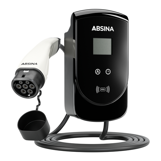
Summary of Contents for ABSINA WALLBOX
- Page 1 OPERATING MANUAL WALLBOX 11kW | 16A Part no.: 34-116-1002...
-
Page 2: Table Of Contents
6. BLOCKSCHALTBILD PRODUKTZEICHNUNG 8. WANDHALTERUNG 9. BEDIENELEMENTE 10. LCD DISPLAY 11. HINWEISE BEI 1-PHASIGER LADUNG 12. VOR DER INBETRIEBNAHME 13. EINSCHALTEN DER WALLBOX 14. VORBEREITUNG DES LADEVORGANGS 15. LADEVORGANG 16. LADEVORGANG VORZEITIG BEENDEN 17. FEHLERBESCHREIBUNG 18. TECHNISCHE DATEN 19. LADEDAUER 20. -
Page 3: Willkommen
Gefahr Tod, nehmen. schweren Verletzungen und Verbrennungen! • Betreiben Sie die Wallbox nicht in der Nähe von brennbaren oder explosiven Materialien, Chemika- Keine Verwendung bei Beschädigungen am lien, Gasen oder anderen gefährlichen Gütern. Ladekabel, Gehäuse, Stecker oder Leitung! •... -
Page 4: Installation
5. INSTALLATION 1. Überprüfen Sie die Wallbox nach dem Öffnen auf 5. Entfernen Sie sie Abdeckung der Anschlussleiste auf der Geräterückseite mittels 4 Schrauben (1). Das Vollständigkeit und Beschädigungen. Bei Schäden Eingangskabel ist durch die Gummitülle zu führen informieren Sie sofort den Transportdienst und und mittels Haltebügel und 2 Schrauben mit der... -
Page 5: Blockschaltbild
6. BLOCKSCHALTBILD Eingang Anzeige smodul modul Steuermodul der Not-Aus Wallbox Schalter Stromver Ladeausgang sorgung 7. PRODUKTZEICHNUNG Deutsch . English... -
Page 6: Wandhalterung
4. Verschrauben Sie anschließend das Sicherungs- blech mithilfe von 2 metrischen Schrauben M3x10 an der Wallbox. 5. Hängen Sie daraufhin die Wallbox an der Wand- halterung ein und zeichnen Sie das Bohrloch zum Verschrauben des Sicherungsblechs an der Wand 10. LCD DISPLAY 6. -
Page 7: Hinweise Bei 1-Phasiger Ladung
2. Über die Sensortaste (Uhr-Symbol) kann die 11. HINWEISE BEI 1-PHASIGER LADUNG Startzeit des Ladevorgangs stundenweise von 1h bis Die LCD Anzeige der Wallbox zeigt nur bei Fahrzeugen 15h eingestellt werden, falls der Ladevorgang nicht mit 3-phasiger Ladung die Parameter „aktueller sofort gestartet werden soll. -
Page 8: Ladevorgang Vorzeitig Beenden
16. LADEVORGANG BEENDEN Während der Ladung kann der Ladevorgang wie folgt beendet werden: § Führen Sie die RFID Karte am Empfänger der Wallbox vorbei, um den Ladevorgang vorzeitig zu beenden. Wenn das Fahrzeug entriegelt ist, können Sie den Ladestecker abziehen. -
Page 9: Technische Daten
Output: Max. 11kW 3-phasig 400V 20. LIEFERUMFANG Ausgangsstrom: 8A / 10A / 13A / 16A § 1x Wallbox mit Ladekabel und Ladestecker Typ 2 Fehlerstromerkennung: FI Typ B allstromsensitiv § 3x RFID Card Kontaktwiderstand: ≤0.3mΩ (L/N) § 3x Schrauben 4x40 + 3x Dübel §... - Page 10 8. WALL HOLDING 9. OPERATING ELEMENTS 10. LCD DISPLAY 11. NOTES FOR 1-PHASE CHARGING 12. BEFORE COMMISSIONING 13. SWITCHING ON THE WALLBOX 14. PREPARATION OF THE CHARGING PROCESS 15. CHARGING PROCEDURE 16. TERMINATING THE CHARGING PROCESS PREMATURELY 17. ERROR DESCRIPTION 18.
-
Page 11: Welcome
1- and 3-phase alternating current (AC) With the help of the operating instructions, you will be according to mode 3. The wallbox may only be used in able to make optimum use of the functions of your conjunction with vehicle inlets that comply with wallbox. -
Page 12: Installation
5. INSTALLATION 1. After opening the wallbox, check it for completeness 5. Remove the cover of the connection strip on the back of the unit using 4 screws (1). Feed the input and damage. In the event of damage, inform the... -
Page 13: Block Diagram
6. BLOCK DIAGRAM Input Display module module Wallbox Emergency Stop Control Unit Switch Power Charge Supply Output 7. PRODUCT DRAWING Deutsch . English... -
Page 14: Wall Holding
3. Screw the wall bracket to the wall using 2 of the 5. Sensor key for start 4x40mm screws provided. preselection 4. Then screw the securing plate to the wallbox using 2 6. RFID receiver M3x10 metric screws. 5. Then hang the wallbox on the wall bracket and mark the drill hole for screwing the securing plate to the wall. -
Page 15: Notes For 1-Phase Charging
Turn LED lights up green continuously and the status it to the right to move it to the ON position. The wallbox indicator shows "Ready". is now ready for operation. If it is still in error mode,... -
Page 16: Error Description
16. END THE CHARGING PROCESS During charging, the charging process can be terminated as follows: § Pass the RFID card past the wallbox receiver to end the charging process prematurely. When the vehicle is unlocked, you can disconnect the charging plug. -
Page 17: Technical Data
21. CLEANING AND STORAGE Charging mode: IEC 62196-2, IEC 61851-1 Only clean the wallbox when it is not connected to the Operating humidity: 5%...95% non condensing vehicle. Only clean the charging cable and the dirty contacts with a dry cloth. Never use harsh cleaning... - Page 18 WEEE-Reg.-Nr. DE 77661344...
- Page 19 ANY QUESTIONS? Check our FAQs … https://www.absina.com/pages/faq … or contact our technical support team TECHNICAL SUPPORT HGPOWER GmbH Kurpfalzstr. 28 97944 Boxberg Germany Hotline: +49 7930 9936 220 E-Mail: info@hgpower.de WEEE-Reg.-Nr. DE 77661344...
- Page 20 ABSINA GmbH Carl-Benz-Strasse 9 74722 Buchen GERMANY Hotline: +49 6281 561 550 0 E-Mail: service@absina.de...


Need help?
Do you have a question about the WALLBOX and is the answer not in the manual?
Questions and answers