
Related Manuals for Aqua DGTEC CD


Summary of Contents for Aqua DGTEC CD
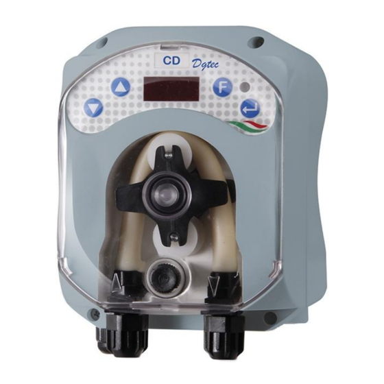
- Page 1 DGTEC Model INSTRUCTION AND MAINTENANCE MANUAL Programmable digital peristaltic pump ENGLISH DGTEC Model CD ADSP7000634 rev. 1.3 23/09/2020 1/36...
- Page 2 dGdoser Model INSTRUCTION AND MAINTENANCE MANUAL Programmable digital peristaltic pump ENGLISH ADSP7000634 rev. 1.3 23/09/2020 2/36...
-
Page 3: Table Of Contents
dGdoser Model INSTRUCTION AND MAINTENANCE MANUAL Programmable digital peristaltic pump ENGLISH CONTENTS INTRODUCTION ……………………………………….…………………………………………………………………………..…………… 4 1.1 Warnings …………………………………………………………………...………………………….………………..………………. 1.2 Standards of reference …………………………………………………………………………………………………………………….. 1.3 Technical features ….. ……………………………………………………………………………………….…..…………………….. 5 1.3.1 Electrical features……………………….………………………………………………………………….…………………….. 5 1.3.2 Performance …………….……………………….……………………………………………………………………………… 5 INSTALLATION ………………………………………………………………………………………………….……………………………… 5 2.1 General rules………. -
Page 4: Introduction
DGTEC Model INSTRUCTION AND MAINTENANCE MANUAL Programmable digital peristaltic pump ENGLISH INTRODUCTION The range of “DGTEC” programmable digital peristaltic pumps is designed to manage dishwashers and consists of the following models: ST Model: single solenoid valve programmable digital pump ... -
Page 5: Technical Features
1.3 TECHNICAL FEATURES 1.3.1 ELECTRICAL FEATURES For the power supply value we recommend reading the label on the pump! 1.3.2 PERFORMANCE Maximum height of the suction tube: 1.5 m Flow rate and back-pressure: refer to Table 1, read the label on the pump to identify the corresponding model. - Page 6 Fig. 1 Foot strainer Tank inlet fitting The full kit supplied is reported in Figure 2. Fig. 2- Installation kit ADSP7000634 rev. 1.3 23/09/2020 6/36...
-
Page 7: Assembly
2.3 ASSEMBLY We always recommend wearing protective masks, gloves, goggles and any other PPE during all installation steps and when handling chemical products. WALL MOUNTING Proceed as follows to secure the pump to the wall: Fix the bracket to the wall using the plugs and screws supplied. ... -
Page 8: Electrical Connections
Connecting the conductivity meter probe 1. Probe 2. Electrodes 3. Maximum level of water 4. Tank wall 5. Rubber gasket 6. Nut 7. Washing pump filter Fig. 5- Conductivity meter probe connection 2.4 ELECTRICAL CONNECTIONS Before performing any intervention on the pump, disconnect the power supply voltage of the machine! Fig. -
Page 9: Hydraulic Connections
2.5 HYDRAULIC CONNECTIONS The CD model enables the dosage of liquid detergent by means of the peristaltic pump, or the dosage of solid detergent by piloting the solenoid valve, which, by regulating the water flow into the dispenser containing the detergent, whether it is granular or in tabs, enables it to dissolve and enter the tank. -
Page 10: Installation For Dosing Solid Detergent
2.5.2 INSTALLATION FOR DOSING SOLID DETERGENT To dose solid detergent, it will be necessary to connect the solenoid valve to the pump output (see Fig. 6). The device will pilot the opening and closing of the solenoid valve to regulate water flow. Fig. -
Page 11: Programming
3.0 PROGRAMMING 3.1 MAIN FEATURES . 9 - U NTERFACE The Increase/Decrease keys allow to change the numerical values and scroll through the lists of options for all the available menu entries. The Enter key allows to access and exit from the various entries of the submenus. Pressing the key for 3 seconds allows, from the Initial Menu, to access the Programming Menu and to go back to the Menu one level up from the main entries on a Menu;... - Page 12 Flow Rate Percentage = 100 * (Nominal Flow Rate/ Read conductivity :1% - 65% Set-point value Effective Flow Rate); Flow Rate Percentage = Read conductivity :65% - 90% Set-point value 80 * (Nominal Flow Rate/ Effective Flow Rate); ...
- Page 13 As in the previous example, the solenoid valve will remain open, thus enabling the passage of water flow until reaching a value of 10 units (~ 110%), and will start dosing again only when the value of measured conductivity goes below 8 units (hysteresis around the Set-point value). The measured conductivity value of a solution is influenced by the temperature as well, and to compensate for this influence you need to know its value.
-
Page 14: Quick Start-Up
From any entry of the Initial Menu you can go to the: Programming Menu by pressing Enter for 3 seconds; User Menu by pressing the F key for 3 seconds; User Menu The User Menu allows you to set fundamental parameters for pump dosing and set-point conductivity. You can browse through the User Menu with the F key and display: ... -
Page 15: Advanced Programming
USER MENU Fig. 11 - Standard programming from User Menu 3.3 ADVANCED PROGRAMMING Here below are the various features of the Programming Menu in greater detail. Every parameter that is changed in the pump's programming is saved when you go back to the initial display. -
Page 16: Displaying And Resetting Statistics
To go back to the main Con entry of the Programming Menu, press Enter for 3 seconds. The applied pressure for 3 seconds to set the Set-point, from the reading entry, assumes that the g/l of optimal detergent has been dissolved in the tank to carry out the wash. Fig. -
Page 17: Setting The Temperature
3.3.4 S ETTING THE EMPERATURE The temperature setting allows you to correct the conductivity value read. From the Programming Menu, after the entry InP, by accessing the entry °C, it is possible to choose between manual setting "noA" and automatic temperature reading "Aut" from the PT100 probe. -
Page 18: Resetting Default Parameters
3.3.6 R ESETTING EFAULT ARAMETERS From the r.P.d entry you will be able to reset the equipment default parameters (refer to the Default Parameters Table in Attachment F). If you choose to reset the initial values, you will go back to the initial display. See Fig. 17. Once you confirm with YES, you cannot go back. -
Page 19: Alarms
The t.on and t.oF entries are visible on the Settings Menu only in the case in which the pump is programmed to pilot the solenoid valve, otherwise by C.d.t, by pressing the F key, it goes back to the first entry of the Settings Menu. To go back to the Programming Menu, to the InP entry, just press Enter for 3 seconds from any entry of the Menu. -
Page 20: Level Alarm
4.3 LEVEL ALARM (only for the model with the level probe) A level probe can be connected to the pump to report the end of the product, which is indicated by the pump in the following way: Audio signal via the buzzer (if there is one on the pump) and if enabled (see A.bu on the “Settings Menu”) with a frequency of 1 second on and 1 second off;... -
Page 21: Temperature Alarm
4.6 TEMPERATURE ALARM The Temperature Alarm is activated whenever the temperature mode (°C) in the Programming Menu is set to automatic “Aut”, but the PT100 probe is not connected (temperature value reported as t - -. The Temperature Alarm is reported in the following way: ... - Page 22 Removing the peristaltic tube Step 1 - Open the front glass Step 2- Turn the roller clockwise and release the (left) intake ring nut Step 3 - Removing the tube Step 4 - Release the (right) delivery ring nut and remove it completely Fig.
-
Page 23: Troubleshooting
Placing back the peristaltic tube Step 1 - Position the tube and secure it on the left-hand side Step 2 - Insert it in the bell by turning the roller Step 3 - Close the front glass Fig. 21- Placing back the peristaltic tube 5.3 TROUBLESHOOTING Problem: the pump does not turn on, the LED and display remain off Solution:... -
Page 24: Returning Material To The After-Sales Service
Problem: liquid leaking from the peristaltic tube Solution: 1. Make sure the delivery and intake tubes are inserted properly and the ring nuts are well tightened. 2. Check the status of the peristaltic tube. If evident malformations are detected, make sure that the material is compatible with the product being dosed by consulting the chemical compatibility table (see ANNEX D), and then go ahead with the replacement. -
Page 25: Attachments
ANNEX A - Overall dimensions ADSP7000634 rev. 1.3 23/09/2020 25/36... -
Page 26: Attachment B - Reference Figures
ANNEX B - Reference Figures Ref. Description Two-coloured LED 3-digit display with 7 segments Roll-holder Peristaltic tube Intake fitting Delivery fitting ADSP7000634 rev. 1.3 23/09/2020 26/36... -
Page 27: Attachment C - Exploded Views
ANNEX C - Exploded views ADSP7000634 rev. 1.3 23/09/2020 27/36... - Page 28 ADSP8000009A COMPLETE ROLLER HOLDERS ADSP9600005 GREY FRONT DGTEC CASING ADSP8000255 RAP 125 24VDC MOTOR ADSP8000217 24VDC 10 l/h motor ADSP6000971 SKD DGTEC CD ADSP8000025 FIXING BRACKET FEMALE BNC PROTECTION FROM BLACK ADSP6000948 RUBBER PANEL ADSP9600006 DGTEC GREY REAR CASING ADSP7000634 rev.
-
Page 29: Attachment D - Chemical Compatibility Table
ANNEX D - Chemical Compatibility Table Key: 1: excellent/good resistance 2: moderate resistance 3: non-resistant EPDM Product Formula Ceram. PVDF PP PVC Hastel. PTFE NBR PE (Viton) (Dutral) Acetic Acid, Max 75% CH3COOH Concentrated Hydrochloric Acid Hydrofluoric Acid, H2F2 Phosphoric Acid, H3PO4 Nitric Acid, 65% HNO3... - Page 30 Key: 1: excellent/good resistance 2: moderate resistance 3: non-resistant Product Formula PharMed Tygon LFL Santoprene Acetic acid 50%- 60% CH3COOH Hydrochloric acid 37% Hydrofluoric Acid 40-48% H2F2 Phosphoric acid H3PO4 Nitric Acid 68%-71% HNO3 Sulphuric Acid 30% H2SO4 Sulphuric Acid 95%-98% H2SO4 Amines R-NH2...
-
Page 31: Attachment E - Default Parameters
ANNEX E - Default Parameters Default Parameters Table IT parameter EN parameter Meaning Value A.bu b.En Buzzer Enabling C.d.t Temperature coefficient 2.0 % Language Over-dosage Alarm Time OFF (disabled) O.F.d O.F.d Maintenance Time 0 sec (disabled) OF.r OF.r OFA 2 Alarm Reset Online Password Set-point conductivity... -
Page 32: Attachment F - Acronym Table
ANNEX F- Acronyms Table IT acronym En acronym Meaning A.bu En.b Buzzer Enabling Priming Aut/noA Aut/noA Automatic/Non-automatic (manual) C.d.t Temperature coefficient Error No Water in the Tank HI.C HI.C High conductivity Settings Reading (Conductivity value read) Language Lo.C Lo.C Low conductivity Over-dosage Alarm Time O.F.d O.F.d... -
Page 33: Attachment G - Menu Layouts
ANNEX G - Menu Layouts Initial Menu User Menu ADSP7000634 rev. 1.3 23/09/2020 33/36... - Page 34 Programming Menu Statistics Menu Settings Menu ADSP7000634 rev. 1.3 23/09/2020 34/36...
- Page 35 Pursuant to art. 13 of Leg. Decree no. 151 dated 25/07/2005 (implementation of Directives 2002/95/EC, 2002/96/EC, 2003/108/EC) it is notified that: The electric and electronic devices must not be considered as household waste. Consumers must, by law, return the electric and electronic devices at the end of their useful life to adequate recycling centres. The crossed-out waste bin symbol on the product, on the instruction manual or on the packaging indicates that the product is subject to the disposal rules envisioned by the Standard.
- Page 36 DGTEC CD ADSP7000634 rev. 1.3 23/09/2020 36/36...
Need help?
Do you have a question about the DGTEC CD and is the answer not in the manual?
Questions and answers