Advertisement
Advertisement
Table of Contents

Related Manuals for Aqua HC 100


Summary of Contents for Aqua HC 100
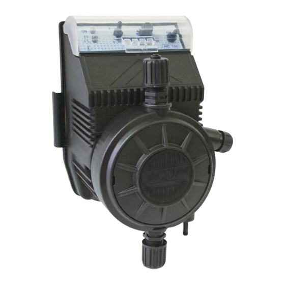
- Page 1 OPERATING AND MAINTENANCE INSTRUCTIONS HC 100...
-
Page 2: Table Of Contents
ENGLISH INDEX 1.0 GENERAL COMMENTS 1.1 Warnings 1.2 Design Standard 2.0 TECHNICAL CHARACTERISTICS 2.1 General Rules 2.2 Standard accessories supplied 2.3 Electrical characteristics 2.4 Electric connection 2.5 Hydraulic Connection 2.6 Operation Programming 3.0 MAINTENANCE 3.1 General maintenance comments 3.2 Periodic maintenance 3.4 Replacing worn parts 3.5 Commonly reported problems Chemical Compatibility Table... -
Page 3: General Comments
ENGLISH 1.0 GENERAL COMMENTS 1.1 Warnings The aim of HC100 pump manual is to provide you with all the necessary information for the correct installation and maintenance in order to give you optimum results whilst in operation. For this reason it is really important you read giving attention to the instructions given below since they furnish all the indications necessary for the correct installation, use and maintenance ... -
Page 4: Technical Characteristics
ENGLISH 2.0 TECHNICAL CHARACTERISTICS 2.1 General rules Install the pump: In a Vertical reinforcement (ex: Wall) or on the pump stand (optional) so that the pump head stays always in vertical position +/-15°. Far from a hot source in dry places at maximum temperature of 45°C and minimum 0°C. -
Page 5: Hydraulic Connection
ENGLISH ENGLISH 2.5 Hydraulic connection After the mounting of the pump, proceed with the hose connections. Suction: connect the suction tube (PVC soft clear) to the foot filter that is supplied and put it in the hose clamp, lock the tube closing the nut. If it utilises a level probe, this one has to be connected to the filter through the support that is supplied. -
Page 6: Programming
RED (emits every time the pump pulses). The HC 100 series allows you to regulate the flow in a more precise way, The output volume is controlled by adjusting the number of pulses per minute which is done using the controls on the front panel, You can adjust the pump between 0 - 100% or 0- 20% of it's maximum output. -
Page 7: Maintenance 3.1 General Maintenance Comments
Dimensions Series HC 100 pump - wall mounting (Fig. 1) Series HC 100 pump - base mounting (Fig. 2) Connection and exploded views Tubing connections on pump head (Fig. 3) Manual purge (Fig. 4) HC 100 series description (Fig. 5) Pump head ball and lip valves (Fig. -
Page 8: Replacing Worn Parts
ENGLISH ATTENTION!!!!! It’s necessary to effectuate all the operations with gloves and glasses suitable for the product used then consult the supplier of the chemical product. 3.4 Replacing worn parts Fuse replacement. Proceed as follows: 1. Put at minimum the knob of the piston regulation of the run (in the pump where it is present) 2. -
Page 9: Commonly Reported Problems
ENGLISH 3.5 Commonly reported problems THE PUMP DOES NOT FUNCTION AND THE GREEN LED IS NOT LIT. Solutions 1. Check that the electrical connection is correctly made. 2. Check that the fuse has not blown 3. Replace the electronic circuit with a new one. THE PUMP FUNCTION CORRECTLY BUT NO LIQUID IS INJECTED IN THE PLANT Solutions 1. -
Page 10: Chemical Compatibility Table
ENGLISH Chemical Compatibility Table Dosing pumps are widely used for dosing chemical products. It is important to select the most suitable material for the liquid to be dosed. The CHEMICAL COMPATIBILITY TABLE is a precious aid to that end. The following Table must be used as an indicative instrument. Modifications in the transported fluid composition or particular service conditions can reduce the resistance of the materials. -
Page 11: Warranty Certificate
ENGLISH ENGLISH Disclaimer The information included in these tables has been obtained from highly qualified sources which we deem reliable and they are provided without any guarantee, explicit or implicit, concerning their exactness. Conditions or methods for handling, storage and use of the material are beyond our control and/or knowledge. - Page 12 Fig. 1 “HC 1” WALL MOUNTING Fig. 2 “HC 1” BASE MOUNTING HC100/N/240717/NW...
-
Page 13: Connections
Ball valves Purge Valve & Hose clamp Lip valves Fig. 3 & 4 PUMP HEAD TUBING CONNECTIONS HC100/N/240717/NW... - Page 14 Fig. 5 Pump parts drawing HC100/N/240717/NW...
- Page 15 COMPLETE HEAD 2-15 PVC-CE-VT AUT. DISCHARGE ADSP6000136P COMPLETE HEAD 2-15 PVC-PVDF-CE-VT AUT. DISCHARGE ADSP6000543 BLACK COVER ADSP6000748 SCREW M 2,9 X 13 UNI 6955 ADSP6000556 YELLOW LABEL WITH AQUA LOGO ADSP6000415 PTFE DIAPHRAGM 1L ADSP6000416 PTFE DIAPHRAGM 2-15L ADSP6000421 PISTON FLANGE 2-6L ADSP6000420...
- Page 16 HC100/N/240717/NW...
- Page 17 DESCRIZIONE ADSP6000137N PUMP HEAD 2-15L PP ADSP6000137P PUMP HEAD 2-15L PVDF ADSP6000018 PUMP HEAD 1L PP ADSP6000022 PUMP HEAD 2-15L 4-20BAR PVC ADSP6000021 PUMP HEAD 20L PP ADSP6000021P PUMP HEAD 20L PVDF ADSP6000024 PUMP HEAD 30-50L PVC ADSP6000129 PUMP HEAD 2-15L PVC SELF DISCHARGE ADSP5007003 OR 3200 VITON 50,47X2,62 / (FOR 2-15L PUMP HEAD) ADSP5007004...
- Page 18 ADSP5008003 OR 2062 SILICONE 15,60X1,78 / ADSP5009004 OR 2062 PTFE 15,60X1,78 / ADSP5007006 OR 2081 VITON NERO 20,35X1,78 / (FOR 30-50L PUMP HEAD) ADSP5007007 OR 2081 DUTRAL 20,35X1,78 / (FOR 30-50L PUMP HEAD) ADSP5005I06 BALL VALVE 3/8" PP-GL-VT ADSP5005014 BALL VALVE 3/8" PP-GL-DT ADSP5005025 BALL VALVE 3/8"...
- Page 19 NOTES: HC100/N/240717/NW...
- Page 20 AQUA WATER SYSTEMS LTD Unit 135 Oak Drive Hartlebury Trading Estate, Hartlebury Worcestershire. DY10 4JB Tel: +44 (0)1299 251050 www.aquaindustrialgroup.co.uk e-mail: sales@askaqu.co.uk HC100/N/240717/NW...
Need help?
Do you have a question about the HC 100 and is the answer not in the manual?
Questions and answers