Table of Contents
Advertisement
Quick Links
Advertisement
Table of Contents

Related Manuals for Mastech MS8211D


Summary of Contents for Mastech MS8211D
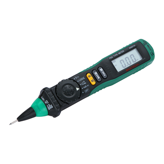
- Page 1 MS8211D DIGITAL MULTIMETER INSTRUCTION MANUAL...
-
Page 2: Table Of Contents
CONTENTS CONTENTS 1. Safety inform........1 4.4 Range Transform........11 1.1 Preliminary..........2 4.5 Auto Power Off........11 1.2 During use..........2 4.6 Preparation For Measurement.....11 1.3 Symbols..........3 4.7 Measuring DC Voltage......12 1.4 Maintenance...........4 4.8 Measuring AC Voltage......13 4.9 Measuring Resistance......15 2. Description........5 4.10 Diode Testing........16 2.1 Names OF Components......5 2.2 Components Elucidation ......6 4.11 Continuity Testing......17... -
Page 3: Safety Inform
1. SAFETY INFORMATION 1.1 Preliminary 1.1.1 When using the meter, the user must observe all normal safety rules concerning: WARNING - Protection against the dangers of electrical current. BE EXTREMELY CAREFUL IN THE USE OF THIS - Protection of the meter against misuse. METER. -
Page 4: Symbols
1.2.5 Do not measure voltage if the voltage on the Conforms to european union directive terminals exceeds 600V above earth ground. Earth ground 1.2.6 Always be careful when working voltages above AC Alternating current 60V DC or 30V AC rms, keep fingers behind the DC Direct current probe barrier while measuring. -
Page 5: Description
2. DESCRIPTION 2.2 Components Elucidation -indicated for information about the Button operation. - This meter is a portable professional measuring instrument with handsome LCD easily reading. Button Function Operation performed - Single operation of a transform switch makes This Button is used to hold data. measurement convenient. -
Page 6: Specifications
- Rotatable Probe Socket 3.2 Electrical Specifications Rotating the probe in or out of the meter. Circumstance Temperature: 23±5°C Relative - Protection Ring Humidity: < 75% To keep the hand from the probe behind the ring. 3.2.1 DC Voltage 3. SPECIFICATIONS Range Accuracy Resolution... -
Page 7: Operating Instruction
3.2.3 Resistance 3.2.6 DC Current Range Accuracy Range Resolution Accuracy Resolution ± (1.0% of rdg + 3 digits) 200Ω 0.1Ω 20mA 0.01mA ± (1.5% of rdg +3 digits) 2KΩ 0.001KΩ 200mA 0.1mA ± (1.0% of rdg + 1 digits) 20KΩ 0.01KΩ... -
Page 8: Maximum Value Measuring And Hold
4.2 Maximum Value Measuring And Hold 4.6.2 When measuring, at first, connect to the public (COM) testing line, then connect the probe tip of the meter to At the range of voltage, you can put on “MAX.H” the circuit under test. button, it will hold the maximum value;... -
Page 9: Measuring Ac Voltage
4.7.5 Connect the probe tip of the meter and probe tip of the test lead (or test clip) across the power source or be loaded on the two sides under measurement. 4.7.6 You can get a reading from LCD display. The polarity of the tested terminal which the tip of the meter connection will be indicated. -
Page 10: Measuring Resistance
4.9 Measuring Resistance - For measuring resistance above 1MΩ, the meter may take a few seconds to get stable reading. 4.9.1 Rotate the probe socket clockwise to spin out the - When the input is not connected, i.e. at open circuit, probe from the meter. -
Page 11: Measuring Dc Current
NOTE: 4.11 Continuity Test - If the input open circuit (or the circuit resistance WARNING measured is higher than 200Ω), then the figure‘0L’ Risk of Electrocution. will be displayed. When testing the circuit continuity, be sure 4.12 Measuring DC Current that the power of the circuit has been shut down and all capacitors have been discharged WARNING... -
Page 12: Measuring Ac Current
4.13 Measuring AC Current 4.14 Logic Test WARNING WARNING Risk of Electrocution. Risk of Electrocution. You can’t input the voltage which is higher than To avoid damage to the Meter or injury if the 100V rms AC, it may damage the inner circuit or fuse blows, never attempt an in-circuit current cause electrical shock. -
Page 13: Maintenance
5. MAINTENANCE 6. ACCESSORIES 5.1 Battery Replacement Test Lead: Electric Ratings 600V 10A one piece Test Clip: Electric Ratings 600V 10A one piece WARNING Before attempting to open the battery cover Battery:1.5V, AAA two pieces of the meter, be sure that the probe tip of the one piece Instruction Manual meter and test lead (or test clip) have been... - Page 14 HYS006756...
Need help?
Do you have a question about the MS8211D and is the answer not in the manual?
Questions and answers