Table of Contents
Advertisement
Advertisement
Table of Contents

Related Manuals for Mastech MS8233E


Summary of Contents for Mastech MS8233E
- Page 1 DIGITAL MULTIMETER MODEL: MS8233E Users Manual...
-
Page 2: Table Of Contents
Table of Contents This manual is used to MS8233E Digital Muti Meter only.. 1. Introduction This Meter is a handheld and battery operated Digital Multi Meter(DMM) with 2. Safety note multi function. This Meter is designed to meet IEC61010-1 &... -
Page 3: Explanation Of Controls And Indicators
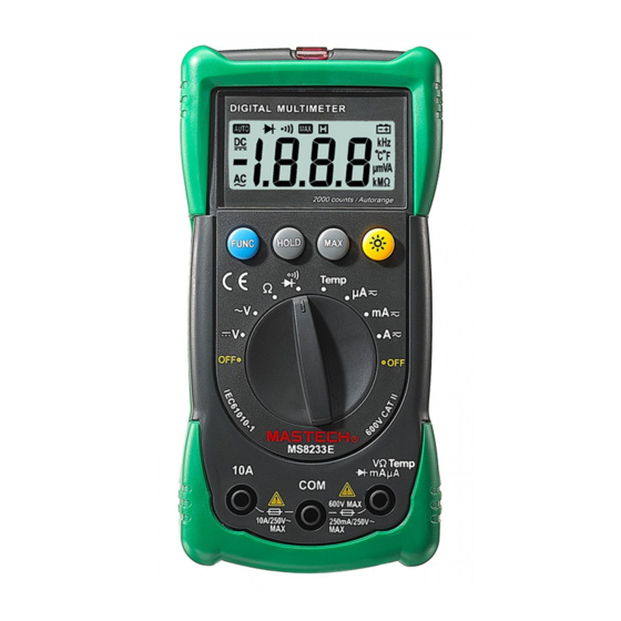
temperature and humidity or dew full. 3. Explanation of controls and indicators Inspect the test lead for damaged insulation or exposed metal. Before measuring current, check the Meter’s fuses and turn off 3-1. Meter illustration power to the circuit before connecting the meter to the circuit. ... -
Page 4: Functional Push Button
① LCD display and ℃/℉. ② “MAX” push button Press “HOLD” to enter and exit the hold mode in any mode. HOLD ③ “BACK LIGHT” push button That act with trigger. ④ ‘HOLD” push button This key is act with trigger. Press this key once, the ⑤... -
Page 5: Specification
- 5 - 3-3. Display indicators Number Indicator Meaning DC voltage or current AC voltage or current Diode Maximum value HOLD Data hold Low battery indicator Ω KΩ MΩ is unit of resistance MKΩ Fig. 2 The unit of temperature ℃/℉... -
Page 6: Electrical Specification
● Auto Power- OFF. : If the meter is idle for 15 minutes (idle time), the meter * Over load protection: SG(Spark Gap) used to protect that the voltage automatically turns the power off. After auto power-off, pushing any of the push overred 1500V button or changing the rotary switch can turn on the meter again. - Page 7 at ‘mA’ input terminal and 10A at ‘10A’ input 4.2.5 Continuity * Max input current::250mA terminal.. . Range Function If measured resistance less than 100Ω, will 4.2.8 Temperature buzzer is sounded. You can selecting Centi-degree[℃] or Fahrenheit[℉] by “FUNC” key. * Open voltage: about 0.5V 4.2.6 DC Current Range...
-
Page 8: Measurement Operation
5-2. Resistance measurement 5. Measurement operation The resistance range are: 200.0Ω, 2.000KΩ,20.00KΩ, 200.0KΩ , 5-1 DC & AC voltage measurement 2.000MΩ. 20.00MΩ. Warning To measure resistance, connect the meter as follows: 1. Insert the red test lead into the ”VΩ” terminal and the black test lead into To avoid harms to you or damage to the meter from electric shock. -
Page 9: Diode/Continuity Check
5-3. Diode/Continuity check NOTE: Input signal level must be higher than 0.5V (it is sensitivity). ① Set the rotary switch to “ ” position. First time, default 5-4. DC/AC µA or mA measurement mode is diode check mode. You can enter the continuity check mode by the “... -
Page 10: Temperature Measurement
5-6. Temperature measurement 6. Maintenance To measuring temperature shuld be use the K-type probe :P3400. 1. Set the rotary switch to the “TEMP” range. In this time, The 6-1. Replacing the battery environment temperature value displayed on the LCD. When meter display the battery must be replace to maintain 2. -
Page 11: Cleaning And Decontamination
6-3. Test lead replacement The test lead has been used and replaced shall be comply with the requirements specified by the manufacturer in order to ensure operation safety,(1000v CATII or 600V CAT III 10 A or better) warning TO AVOID ELECTRICAL SHOCK, REMOVE TEST LEADS BEFORE OPENING BATTERY COVER.
Need help?
Do you have a question about the MS8233E and is the answer not in the manual?
Questions and answers