Table of Contents
Advertisement
Quick Links
Advertisement
Table of Contents

Related Manuals for LINOVISION IOT-G67

Summary of Contents for LINOVISION IOT-G67
- Page 1 Outdoor ® LoRaWAN Gateway IOT-G67 Quick Start Guide...
- Page 2 Safety Precautions Linovision will not shoulder responsibility for any loss or damage resulting from not following the instructions of this operating guide. ● The device must not be modeled in any way. ● Do not place the device close to objects with naked flames.
-
Page 3: Table Of Contents
Contents 1. PackingList ................................4 2. HardwareIntroduction ............................5 2.1Overview ..............................5 2.2Dimensions..............................5 2.3LED Indicators ............................5 2.4Reset Button .............................. 6 2.5DC Power Connector..........................6 3. HardwareInstallation............................7 3.1SIM CardInstallation ..........................7 3.2AntennaInstallation..........................7 3.3EthernetCable& Power Cable Installation..................3.4Power Supply ............................8 3.5GatewayInstallation ..........................9 3.5.1Wall Mounting.......................... -
Page 4: Packinglist
1. Packing List ® Before you begin to install the G67 LoRaWAN Gateway, please check the package contents to verify that you have received the items below. 1 ×G67 1 ×PoE Injector 1 ×Mounting Bracket 4 ×Wall Mounting Kits 1 ×Cable Gland 1 ×SIM Dust Cover 2 ×Hose Clamps 1 ×DC Power Cable... -
Page 5: Hardwareintroduction
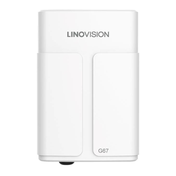
2. Hardware Introduction 2.1 Overview LoRa Antenna Connector Vent Plug SIM Slot LED Area & Type-CPort & Reset Button SYS: System Indicator LoRa: LoRa Indicator LTE: Cellular Indicator DC Power Connector (Solar Connector) Ethernet Port (PoE) Mounting Bracket 2.2 Dimensions (mm) 2.3 LED Indicators Indication Status... -
Page 6: Reset Button
Blinking rapidly: SIM card has been registered and is dialing up now Static: SIM card has been registered and dialed up successfully 2.4 Reset Button Description Function SYS LED Action Static Green Press and hold the reset buttonfor more than 5 seconds. Static Green →... -
Page 7: Hardwareinstallation
3. Hardware Installation 3.1 SIM Card Installation A. Insert the SIM card into the device according to the direction icon on the device. If you need to take out the SIM card, press into the SIM card and it will pop up automatically. B. -
Page 8: Ethernetcable& Power Cable Installation
3.3 Ethernet Cable & Power Cable Installation Pass the Ethernet cable through the cable gland and rotate the cable gland to gateway, then tighten the cable gland with wrench. For DC or solar power supply, remove the protective cap of power connector and rotate the DC power cable into the power connector. -
Page 9: Gatewayinstallation
3.5 Gateway Installation G67 can be mounted to a wall or a pole. Before you start, make sure that your SIM card has been inserted, your antennas have been attached and all cables have been installed. Note: Do not connect device to power supply or other devices when installing. 3.5.1 Wall Mounting Preparation: mounting bracket (with a screw), wall plugs, wall mounting screws and other required tools. -
Page 10: 2Pole Mounting
3.5.2Pole Mounting Preparation: mountingbracket , hose clamp and other requiredtools. (with a screw) A. Loosen the hose clamp by turningthe locking mechanism counter-clockwise. B. Straighten out the hose clamp and slide it through the rectangular rings in the mounting bracket, wrap the hose clamp around the pole. -
Page 11: Loginthe Web Gui
4. Login the Web GUI G67 provides web-basedconfiguration interface for management. If this is the first time you configure the gateway, please use the default settings below: ETH IP Address: 192.168.23.150 Wi-Fi IP Address: 192.168.1.1 Wi-FiSSID: Gateway_****** Username: admin Password: password 4.1 Wireless Access A. -
Page 12: Wiredaccess
E. You can view system information and perform configuration of the gateway. 4.2 Wired Access Connect PC to G67 ETH port through PoE injector. The following steps are based on Windows 10 operating system for your reference. A. Go to “Control Panel” → “Network and Internet” → “Network and Sharing Center”, then click “Ethernet”... - Page 13 C. Open a Web browser on your PC (Chrome is recommended) and type in the IP address 192.168.23.1 50 to access the web GUI. D. Enter the username and password, click “Login”. If you enter the username or password incorrectly more than 5 times, the login page will be locked for 10 minutes.
-
Page 14: Networkconnection
5. Network Connection This section explains how to connect the gateway to network via WAN connection, Wi-Fior cellular. 5.1 Configure the Ethernet Connection A. Go to “Network”→ “Interface” → “Port” page to select the connection type and configure Ethernet port information. B. - Page 15 C. Type the key of Wi-Fi. D. Go to “Status”→”WLAN” to check Wi-Fistatus. If it shows “Connected”,it means gateway connects to Wi-Fisuccessfully.
-
Page 16: Configurethecellularconnection
5.3 Configure the Cellular Connection A. Go to “Network”→ “Interface” → “Cellular”→ “CellularSetting” page to enable cellular settings. B. Choose relevant network type and fill in SIM card information like APN or PIN code. C. Click “Save” and “Apply” for changes to take effect. D. -
Page 17: Packet Forwarderconfiguration
6. Packet Forwarder Configuration G67 has installed multiple packet forwarders including Semtech, Chirpstack-Generic MQTT broker, etc. This section explains how to connect the gateway to network servers. Make sure the gateway connects to the network as shown in Section A. Go to “Packet Forwarder” → “General”page and click to add a network server. - Page 18 D. Add the gateway on network server page. For more details about the network server connection please refer to IoT Support portal. E. Go to “Traffic” page to view the data communication of G67.
-
Page 19: Networkserver Configuration
7. Network Server Configuration UG67 can work as network server and transmit data to IoT Cloud or other platform via MQTT/HTTP/HTTPS. Make sure the gateway connects to the networkas shown in Section 7.1 Connect G67 to Milesight IoT Cloud A. Go to “Packet Forwarder” → “General” page to enable the embeddednetwork server. B. -
Page 20: Connectug67To Mqtt/Httpserver
D. Log in the IoT Cloud. Then go to “My Devices” page and click “+NewDevices” to add gateway to IoT Cloud via SN. Gateway will be added under “Gateways” menu. The gateway is online on IoT Cloud. 7.2 Connect G67 to MQTT/HTTP Server A. - Page 21 B. Go to “Packet Forwarder” → “Radio” page to select the antenna type, center frequency and channels. The channels of the gateway and nodes need to be the same. C. Go to “Network Server” → “General” page to enable the network server mode. D.
- Page 22 After saving the application, you can select HTTP, HTTPS or MQTT protocol and fill in correspond server information to send data to another server. E. Go to “Profiles” page to add a new profile for the device. ® F. Go to “Device” page and click “Add” to add LoRaWAN node devices.
- Page 23 You can also click “Bulk Import” if you want to add many nodes all at once. Click “Template Download” to download template file and add device information to this file. Application and device profile should be the same as you created on web page. Import this file to add bulks of devices.
- Page 24 Click “Details” to check the properties and payload contents of packets. [END]...
Need help?
Do you have a question about the IOT-G67 and is the answer not in the manual?
Questions and answers