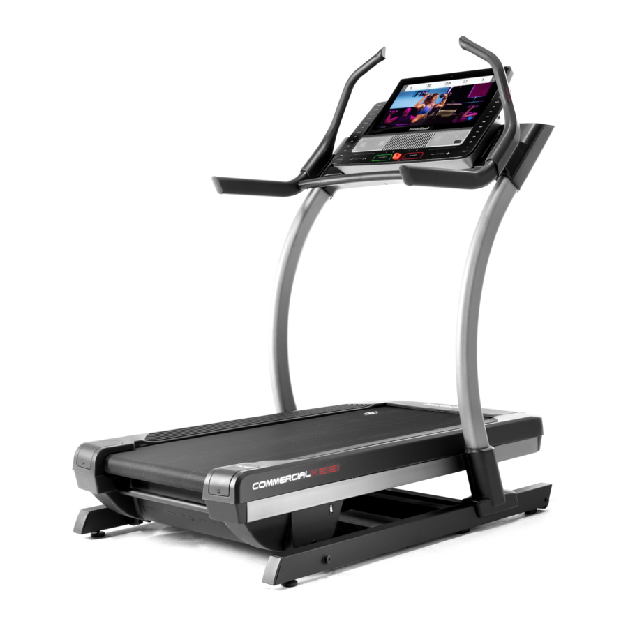
NordicTrack COMMERCIAL X22i User Manual
Hide thumbs
Also See for COMMERCIAL X22i:
- User manual (40 pages) ,
- User manual (36 pages) ,
- User manual (39 pages)
Advertisement
Table of Contents
- 1 Table of Contents
- 2 Warning Decal Placement
- 3 Important Precautions
- 4 Before You Begin
- 5 Part Identification Chart
- 6 Assembly
- 7 How to Use the Treadmill
- 8 Fcc Information
- 9 How to Move the Treadmill
- 10 Maintenance and Troubleshooting
- 11 Exercise Guidelines
- 12 Part List
- 13 Exploded Drawing
- 14 Ordering Replacement Parts
- 15 Limited Warranty
- Download this manual
nordictrack.com
Model No. NTL29222.2
Serial No.
Write the serial number in the space
above for reference.
Serial Number
Decal
REGISTER YOUR
PRODUCT
To register your product and
activate your warranty today, go
to my.nordictrack.com.
MEMBER CARE
For service at any time, go to
my.iFIT.com.
Or call 1-833-680-IFIT
(1-833-680-4348)
Mon.–Fri. 6 a.m.–6 p.m. MT
Sat. 8 a.m.–12 p.m. MT
Please do not contact the store.
CAUTION
Read all precautions and
instructions in this manual before
using this equipment. Keep this
manual for future reference.
USER'S MANUAL
Advertisement
Table of Contents

Related Manuals for NordicTrack COMMERCIAL X22i


Summary of Contents for NordicTrack COMMERCIAL X22i
- Page 1 Serial Number Decal REGISTER YOUR PRODUCT To register your product and activate your warranty today, go to my.nordictrack.com. MEMBER CARE For service at any time, go to my.iFIT.com. Or call 1-833-680-IFIT (1-833-680-4348) Mon.–Fri. 6 a.m.–6 p.m. MT Sat.
-
Page 2: Table Of Contents
The decals are attached to both sides of the treadmill. NORDICTRACK and IFIT are registered trademarks of iFIT Inc. The Bluetooth word mark and logos are regis- ® tered trademarks of Bluetooth SIG, Inc. and are used under license. Google Maps is a trademark of Google LLC. -
Page 3: Important Precautions
6. Use the treadmill only as described in this purchase a surge suppressor, see your local manual. NORDICTRACK dealer, call the telephone number on the front cover of this manual, or 7. The treadmill is intended for home use only. - Page 4 19. Read, understand, and test the emergency page 8 and HOW TO MOVE THE TREADMILL stop procedure before using the treadmill (see on page 31.) You must be able to safely lift 45 HOW TO TURN ON THE POWER on page 21). lbs.
- Page 5 STANDARD SERVICE PLANS...
-
Page 6: Before You Begin
BEFORE YOU BEGIN Thank you for selecting the new NORDICTRACK reading this manual, please see the front cover of this ® COMMERCIAL X22I treadmill. The COMMERCIAL manual. To help us assist you, note the product model X22I treadmill provides an impressive selection of number and serial number before contacting us. -
Page 7: Part Identification Chart
PART IDENTIFICATION CHART Use the drawings below to identify small parts used for assembly. The number in parentheses below each draw- ing is the key number of the part, from the PART LIST near the end of this manual. The number following the key number is the quantity used for assembly. -
Page 8: Assembly
ASSEMBLY 1. To use the assembly steps in this manual, first see the helpful tips below. • Assembly requires two persons. • To identify small parts, see page 7. • Place all parts in a cleared area and remove the •... - Page 9 2. Make sure that the power cord is unplugged. Be careful not to pinch the wires (A–D) during this step. Use the built-in handle (E) as you lift the upright assembly (F). Make sure that the Carriage Brackets (82) on the upright assembly (F) are in the positions shown.
- Page 10 4. Cut and remove the shipping tie (G) from each side of the Base (64) (only one side is shown). 5. Make sure that the holes in the Carriage Brackets (82) are aligned with the holes in the Frame (83). If necessary, grip both sides of the frame assembly (H) near the rear and push forward or pull backward to align the holes.
- Page 11 6. Firmly tighten the four indicated 3/8" x 3 3/4" Screws (3). Then, remove the yellow shipping screw (I) from each side of the treadmill (only one side is shown). Discard the shipping screws. 7. Press the Motor Hood Cover (65) down onto the Motor Hood (66) until all four corners and the center snap into place.
- Page 12 8. Insert the top edge of the Upright Panel (109) into the opening in the upright assembly (F). Attach the Upright Panel with two #8 x 3/4" Screws (2). Be careful not to overtighten the Screws. 9. Remove the two indicated wingnuts (W) and bolts (J), and lift out the shipping tube (K).
- Page 13 10. Be careful not to pinch the wires (L, M) during this step. With the help of a second person, set the console base assembly (N) on the upright assembly (F). Attach the console base assembly (N) with two 3/8" x 2 1/4" Screws (1) and two 3/8" x 3 3/4" Screws (3).
- Page 14 12. Identify the left handrail assembly (P). Attach the left handrail assembly to the left side of the console base assembly (N) with two 3/8" x 2 1/4" Screws (1); do not fully tighten the Screws yet. 13. Attach the right handrail assembly (Q) to the right side of the console base assembly (N) with two 3/8"...
- Page 15 14. Orient the crossbar assembly (R) as shown. Attach the crossbar assembly to the left and right handrail assemblies (P, Q) with four 1/4" x 3/4" Screws (5); start all four Screws, and then tighten them. Then, tighten the four indicated 3/8" x 2 1/4" Screws (1).
- Page 16 16. Attach the Console Cover (120) to the bottom of the Primary Console (119) with four #8 x 3/4" Screws (2); start all four Screws, and then tighten them. Be careful not to overtighten the Screws. 17. Be careful not to pinch any wires during this step.
- Page 17 18. Connect the wires (T) from the console assem- bly (S) to the corresponding wires (U) from the console upright assembly (V). The wire connec- tors should slide together easily and snap into place with an audible click. If they do not, turn one connector and try again.
- Page 18 Save all of the included tools in case adjustments are needed in the future. Note: Extra hardware may be included. To register your product and activate your warranty today, go to my.nordictrack.com.
-
Page 19: How To Use The Treadmill
HOW TO USE THE TREADMILL HOW TO CONNECT THE POWER CORD capable of carrying 15 or more amps. To avoid overloading the circuit, do not plug other electrical Use a Surge Suppressor devices, except for low-power devices such as cell phone chargers, into the surge suppressor or into Your treadmill, like other electronic equipment, can be an outlet on the same circuit. - Page 20 CONSOLE DIAGRAM workouts, record your workout results, set and track FEATURES OF THE CONSOLE fitness goals, and access many other features. The advanced treadmill console offers a selection of features designed to make your workouts more effec- When you use the manual mode of the console, you tive and enjoyable.
- Page 21 HOW TO TURN ON THE POWER HOW TO USE THE TOUCH SCREEN The console features a tablet with a full-color touch IMPORTANT: If the treadmill has been exposed to screen. The following information will help you become cold temperatures, allow it to warm to room tem- familiar with the tablet’s advanced technology: perature before you turn on the power.
- Page 22 HOW TO SET UP THE CONSOLE 5. Calibrate the incline system. Before using the treadmill for the first time, set up the First, touch the menu button (three horizontal lines symbol), touch Settings, touch Maintenance, touch console. Calibrate Incline, and then touch Begin to calibrate the incline system.
- Page 23 HOW TO USE THE MANUAL MODE 4. Change the incline of the treadmill as desired. To change the incline of the treadmill, press the 1. Insert the key into the console. incline increase and decrease buttons or one of the See HOW TO TURN ON THE POWER on page 21.
- Page 24 6. Turn on the fan if desired. HOW TO USE THE SLED PUSH FEATURE The fan features sev- 1. Insert the key into the console. eral speed settings, as well as an auto See HOW TO TURN ON THE POWER on page 21. speed mode.
- Page 25 HOW TO USE A FEATURED WORKOUT 4. Start the workout. Note: To use a featured workout, the console must Touch Start Workout to start the workout. be connected to a wireless network (see HOW TO CONNECT TO A WIRELESS NETWORK on page 30). During some workouts, an iFIT coach will guide you through a video workout.
- Page 26 5. Use headphones if desired. 3. Draw your map. To connect your headphones to the console, first Navigate to the area on the map where you want turn on your headphones, place them in pairing to draw your workout by sliding your fingers on the mode, and place them near the console.
- Page 27 HOW TO USE AN IFIT WORKOUT 4. Select an iFIT workout from the home screen or the workout library. To use an iFIT workout, the console must be connected to a wireless network (see HOW TO CONNECT TO A Touch the buttons at the bottom of the screen to WIRELESS NETWORK on page 30).
- Page 28 6. Create a list of favorite iFIT workouts if desired. HOW TO CHANGE CONSOLE SETTINGS To mark an iFIT workout as a favorite, simply view IMPORTANT: Some of the settings and features the overview or workout summary of the desired described may not be enabled.
- Page 29 3. Customize the time zone and other settings. 6. Calibrate the incline system of the treadmill. To customize the time zone or other settings, touch Touch Calibrate Incline, and then touch Begin Equipment Settings and then touch the desired to calibrate the incline system. The treadmill will settings.
- Page 30 To disconnect from a wireless network, touch and HOW TO CONNECT TO A WIRELESS NETWORK hold the name of the wireless network and then The console is Wi-Fi enabled, allowing you to set up a touch Forget. wireless network connection. If you are having problems connecting to an encrypted network, make sure that your password 1.
-
Page 31: Fcc Information
FCC INFORMATION This console has been tested and found to comply with the limits for a Class B digital device, pursuant to part 15 of the FCC Rules. These limits are designed to provide reasonable protection against harmful interference in a residential installation. This equipment generates, uses, and can radiate radio frequency energy and, if not installed and used in accordance with the instructions, may cause harmful interference to radio communications. -
Page 32: Maintenance And Troubleshooting
MAINTENANCE AND TROUBLESHOOTING c. Check the power switch located on the treadmill MAINTENANCE frame near the power cord. If the switch protrudes Regular maintenance is important for optimal as shown (A), the switch has tripped. To reset the performance and to reduce wear. Inspect and prop- power switch, wait for five minutes and then press erly tighten all parts each time the treadmill is used. - Page 33 c. Your treadmill features a walking belt coated with SYMPTOM: The walking belt slows when walked on high-performance lubricant. IMPORTANT: Never a. Use only a surge suppressor that meets all of the apply silicone spray or other substances to specifications described on page 19. the walking belt or the walking platform unless instructed to do so by an authorized service b.
- Page 34 b. If the walking belt slips when walked on, first SYMPTOM: The displays of the console do not remove the key and UNPLUG THE POWER function properly CORD. Using the hex key, turn both idler roller screws clockwise, 1/4 of a turn. When the walking a.
-
Page 35: Exercise Guidelines
EXERCISE GUIDELINES Aerobic Exercise—If your goal is to strengthen your WARNING: cardiovascular system, you must perform aerobic Before beginning this exercise, which is activity that requires large amounts or any exercise program, consult your physi- of oxygen for prolonged periods of time. For aerobic cian. -
Page 36: Part List
PART LIST Model No. NTL29222.2 R0522B Key No. Qty. Description Key No. Qty. Description 3/8" x 2 1/4" Screw Thin Lift Frame Pivot Bushing #8 x 3/4" Screw Lift Frame 3/8" x 3 3/4" Screw 1" Grommet M6 x 20mm Screw Cable Tie 1/4"... - Page 37 Key No. Qty. Description Key No. Qty. Description Upright Crossbar Frame Incline Motor Spacer Crossbar Top Incline Motor Pin Console Front Incline Motor Pivot Cover Carriage Console Plate Rear Upright Cover Pivot Back Cover Upright Cover Console Upper Cover Upright Top Cover Console Lower Cover Upright Panel Console Upright Front Cover...
-
Page 38: Exploded Drawing
EXPLODED DRAWING A Model No. NTL29222.2 R0522B... - Page 39 EXPLODED DRAWING B Model No. NTL29222.2 R0522B...
- Page 40 EXPLODED DRAWING C Model No. NTL29222.2 R0522B...
- Page 41 EXPLODED DRAWING D Model No. NTL29222.2 R0522B...
- Page 42 EXPLODED DRAWING E Model No. NTL29222.2 R0522B...
- Page 43 EXPLODED DRAWING F Model No. NTL29222.2 R0522B...
-
Page 44: Ordering Replacement Parts
ORDERING REPLACEMENT PARTS To order replacement parts, please see the front cover of this manual. To help us assist you, be prepared to provide the following information when contacting us: • the model number and serial number of the product (see the front cover of this manual) •...
Need help?
Do you have a question about the COMMERCIAL X22i and is the answer not in the manual?
Questions and answers
where is the reset button
The reset button on the NordicTrack COMMERCIAL X22i is located inside a small reset opening on the top of the console. To reset, use a bent paper clip to press and hold the reset button inside the opening while another person switches the power to the on (reset) position.
This answer is automatically generated
the belt does not move when the machine is on and connected to the console. the incline/decline responds to the console buttons. the belt moves manually...it is hard to move and seems tight. what do you suggest?
If the belt on a NordicTrack COMMERCIAL X22i does not move while the machine is on but the incline/decline functions work, check the following:
1. Power and Safety Key – Ensure the machine is plugged in, turned on, and the safety key is properly inserted.
2. Walking Belt Alignment – Inspect the walking belt for misalignment or tightness and adjust if necessary.
3. Motor and Drive Belt – Check if the motor is running but the drive belt is disconnected or loose.
4. Console Settings – Verify that the speed is set correctly and not at zero.
5. Calibration – If needed, follow the calibration instructions in the manual.
6. Service Assistance – If the issue persists, contact an authorized service representative.
Avoid sudden speed changes and follow manufacturer guidelines for servicing.
This answer is automatically generated