NordicTrack Commercial U100 User Manual
Uk manual
Hide thumbs
Also See for Commercial U100:
- Bedienungsanleitung (32 pages) ,
- Manuel de l’utillsateur manual (32 pages) ,
- Manuale d'istruzioni (32 pages)
Advertisement
Table of Contents
- 1 Table of Contents
- 2 Warning Decal Placement
- 3 Important Precautions
- 4 Before You Begin
- 5 Part Identification Chart
- 6 Assembly
- 7 The Chest Heart Rate Monitor
- 8 How to Use the Exercise Bike
- 9 Maintenance and Troubleshooting
- 10 Exercise Guidelines
- 11 Part List
- 12 Exploded Drawing
- 13 Ordering Replacement Parts
- 14 Recycling Information
- Download this manual
Model No. NTEVEX78913.0
Serial No.
USER'S MANUAL
Write the serial number in the
space above for reference.
Serial Number
Decal (under frame)
CUSTOMER SERVICE
UNITED KINGDOM
Call: 08457 089 009
From Ireland: 053 92 36102
Website: www.iconsupport.eu
E-mail: csuk@iconeurope.com
Write:
ICON Health & Fitness, Ltd.
c/o HI Group PLC
Express Way
CASTLEFORD
WF10 5QJ
UNITED KINGDOM
AUSTRALIA
Call: 1800 993 770
E-mail: australiacc@iconfitness.com
Write:
ICON Health & Fitness
PO Box 635
WINSTON HILLS NSW 2153
AUSTRALIA
CAUTION
Read all precautions and instruc-
tions in this manual before using
this equipment. Keep this manual
for future reference.
www.iconeurope.com
Advertisement
Table of Contents

Related Manuals for NordicTrack Commercial U100


Summary of Contents for NordicTrack Commercial U100
- Page 1 Model No. NTEVEX78913.0 Serial No. USER’S MANUAL Write the serial number in the space above for reference. Serial Number Decal (under frame) CUSTOMER SERVICE UNITED KINGDOM Call: 08457 089 009 From Ireland: 053 92 36102 Website: www.iconsupport.eu E-mail: csuk@iconeurope.com Write: ICON Health &...
-
Page 2: Table Of Contents
User weight must not exceed 275 pounds. This product should always be used on a level surface. This product is not intended for therapeutic use. Replace label if damaged, illegible, or removed. NORDICTRACK is a registered trademark of ICON IP, Inc. -
Page 3: Important Precautions
IMPORTANT PRECAUTIONS WARNING: To reduce the risk of serious injury, read all important precautions and instructions in this manual and all warnings on the exercise bike before using the exercise bike. ICON assumes no responsibility for personal injury or property damage sustained by or through the use of this product. -
Page 4: Before You Begin
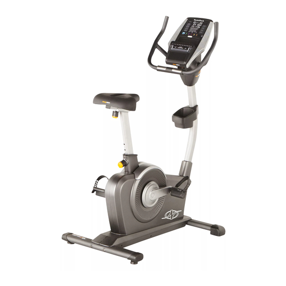
BEFORE YOU BEGIN Thank you for selecting the revolutionary reading this manual, please see the front cover of this NORDICTRACK COMMERCIAL U100 exercise bike. manual. To help us assist you, note the product model ® Cycling is an effective exercise for increasing cardio- number and serial number before contacting us. -
Page 5: Part Identification Chart
PART IDENTIFICATION CHART Use the drawings below to identify the small parts needed for assembly. The number in parentheses below each drawing is the key number of the part, from the PART LIST near the end of this manual. The number following the key number is the quantity needed for assembly. -
Page 6: Assembly
ASSEMBLY • Assembly requires two persons. • In addition to the included tool(s), assembly requires the following tools: • Place all parts in a cleared area and remove the one Phillips screwdriver packing materials. Do not dispose of the packing materials until you finish all assembly steps. - Page 7 3. Set a sturdy piece of packing material under the front of the Frame (1). Have a second person Wheel hold the Frame to prevent it from tipping while you complete this step. Orient the Front Stabilizer (2) as shown. Attach the Front Stabilizer (2) to the Frame (1) with two M10 x 105mm Screws (76).
- Page 8 6. Set the Seat Carriage (24) on the Seat Post (6) and hold it in place. Insert the Adjustment Knob (27) upward into the Seat Post (6), and tighten the Adjustment Knob into the Seat Carriage Block (30) inside the Seat Carriage (24).
- Page 9 8. Attach the Accessory Tray (46) to the Upright (4) with four M4 x 15mm Screws (80). 9. Orient the Handlebar (5) as shown. Avoid pinching Tip: Avoid pinching the Pulse Wire (17) and the wires the Main Wire (58). Attach the Handlebar (5) to the Pivot Bracket (35) with six M8 x 13mm Screws (72).
- Page 10 10. Untie and discard the wire tie (not shown) on the Main Wire (58). Wires Have a second person hold the Console (13) near the Pivot Bracket (35). Insert all the wires on the Console (13) downward through the hole in the center of the Pivot Bracket (35).
- Page 11 12. Tip: It may be necessary to turn the Adjustment Knob (27) and adjust the angle of the Pivot Bracket (35). Attach the Lower Pivot Cover (12) to the Pivot Bracket (35) with two M4 x 12mm Screws (75). Make sure that the indicated wire (A) is not covered by the Lower Pivot Cover (12) (see the drawing in step 13).
- Page 12 15. Identify the Left Pedal (21). Using the included flat wrench, firmly tighten the Left Pedal (21) counterclockwise into the Left Crank Arm (19). Firmly tighten the Right Pedal (not shown) clockwise into the Right Crank Arm (not shown). Strap Adjust the strap on the Left Pedal (21) to the desired position, and press the ends of the strap onto the tabs on the Left Pedal.
-
Page 13: The Chest Heart Rate Monitor
THE CHEST HEART RATE MONITOR HOW TO PUT ON THE HEART RATE MONITOR • Do not expose the heart rate monitor to direct sun- light for extended periods of time; do not expose it to The heart rate temperatures above 122° F (50° C) or below 14° F monitor consists of (-10°... -
Page 14: How To Use The Exercise Bike
HOW TO USE THE EXERCISE BIKE HOW TO PLUG IN THE POWER ADAPTER HOW TO ADJUST THE HEIGHT OF THE SEAT IMPORTANT: If the exercise bike has been exposed For effective exercise, the seat should be at the proper to cold temperatures, allow it to warm to room height. - Page 15 HOW TO ADJUST THE ANGLE OF THE HOW TO ADJUST THE PEDAL STRAPS CONSOLE AND THE HANDLEBAR To adjust the To adjust the pedal straps, first angle of the pull the ends of console and the the straps off the Strap handlebar, simply tabs on the ped-...
- Page 16 CONSOLE DIAGRAM MAKE YOUR FITNESS GOALS A REALITY WITH Upload your workout results to the iFit cloud IFIT.COM and track your accomplishments. With your new iFit-compatible fitness equipment, you can use an array of features on iFit.com to make your Set calorie, time, or distance goals for your fitness goals a reality: workouts.
- Page 17 FEATURES OF THE CONSOLE HOW TO SET UP THE CONSOLE The advanced console offers an array of features Before using the exercise bike for the first time, set up designed to make your workouts more effective and the console. enjoyable. 1.
- Page 18 HOW TO USE THE MANUAL MODE Distance—This display mode will show the dis- tance that you have pedaled in miles or kilometers. 1. Begin pedaling or press any button on the console to turn on the console. Laps—This display mode will show a track that represents 1/4 mile (400 m).
- Page 19 When your pulse is detected, your heart rate When the console is connected to a wireless network, the wireless will be shown. For the most accurate heart symbol in the display will show the rate reading, hold the contacts for at least 15 seconds.
- Page 20 HOW TO USE AN ONBOARD WORKOUT If the resistance level for the current segment is too high or too low, you can manually override the 1. Begin pedaling or press any button on the setting by pressing the Digital Resistance buttons. console to turn on the console.
- Page 21 HOW TO USE A SET-A-GOAL WORKOUT HOW TO CREATE A USER-DEFINED WORKOUT 1. Begin pedaling or press any button on the 1. Begin pedaling or press any button on the console to turn on the console. console to turn on the console. When you turn on the console, the display will turn When you turn on the console, the display will turn on.
- Page 22 HOW TO USE A USER-DEFINED WORKOUT The workout will continue in this way until the last segment ends. To pause the workout, stop pedal- 1. Begin pedaling or press any button on the ing. The time will pause in the display. To resume console to turn on the console.
- Page 23 HOW TO USE AN IFIT WORKOUT For more information about the iFit workouts, please see www.iFit.com. Note: To use an iFit workout, you must have access to a wireless network (see page 24). An iFit account is When you select an iFit workout, the display will also required (see step 1 on page 17).
- Page 24 7. Measure your heart rate if desired. HOW TO CHANGE CONSOLE SETTINGS See step 5 on page 19. The console features a settings mode that allows you to view usage information, to personalize console set- 8. Turn on the fan if desired. tings, and to set up and manage a wireless network connection.
- Page 25 Contrast—The contrast level of the display will iFit User Setup—To set up a different iFit account, appear in the matrix. Press the Digital Resistance but maintain the existing wireless connection, increase and decrease buttons to adjust the con- follow the instructions in the matrix. Note: This option will be used rarely.
- Page 26 Press the up, down, left, and right buttons to high- Log in to your iFit account on the web page. Then, light the desired letter or number. Then, press the enter the numerical code into the indicated field on Enter button to select the letter, number, or symbol. the web page.
- Page 27 HOW TO USE THE SOUND SYSTEM The console will display an IP address, such as 192.168.0.1:8080. Open a web browser on your computer, smart phone, tablet, or other Wi-Fi To play music or audio books through the console device. Next, type in the IP address on the con- sound system while you exercise, plug a 3.5 mm male sole into the URL bar in your browser.
-
Page 28: Maintenance And Troubleshooting
MAINTENANCE AND TROUBLESHOOTING Inspect and tighten all parts of the exercise bike regu- Locate the Reed Switch (57). Loosen, but do not larly. Replace any worn parts immediately. remove, the M4 x 16mm Screw (78). To clean the exercise bike, use a damp cloth and a small amount of mild soap. -
Page 29: Exercise Guidelines
EXERCISE GUIDELINES Burning Fat—To burn fat effectively, you must exer- WARNING: cise at a low intensity level for a sustained period of Before beginning this time. During the first few minutes of exercise, your or any exercise program, consult your physi- body uses carbohydrate calories for energy. -
Page 30: Part List
PART LIST Model No. NTEVEX78913.0 R0813A Key No. Qty. Description Key No. Qty. Description Frame Carriage Cap Front Stabilizer Idler Rear Stabilizer Accessory Tray Upright Resistance Motor Handlebar Medium Shaft Seat Post Seat Post Knob Front Shield Cover Upper Block Top Shield Cover Lower Block Upper Pivot Cover... -
Page 31: Exploded Drawing
EXPLODED DRAWING Model No. NTEVEX78913.0 R0813A... -
Page 32: Ordering Replacement Parts
ORDERING REPLACEMENT PARTS To order replacement parts, please see the front cover of this manual. To help us assist you, be prepared to provide the following information when contacting us: • the model number and serial number of the product (see the front cover of this manual) • the name of the product (see the front cover of this manual) • t he key number and description of the replacement part(s) (see the PART LIST and the EXPLODED DRAWING near the end of this manual) RECYCLING INFORMATION This electronic product must not be disposed of in municipal waste.
Need help?
Do you have a question about the Commercial U100 and is the answer not in the manual?
Questions and answers