
Related Manuals for Fisher & Paykel DD24DCTW9N


Summary of Contents for Fisher & Paykel DD24DCTW9N
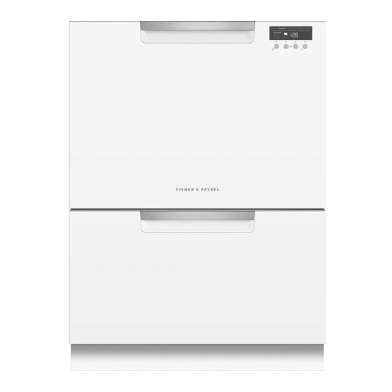
- Page 1 DOUBLE DISHDRAWER DISHWASHER DD24DA & DD24DCT models INSTALLATION GUIDE US CA 591153B 08.17...
-
Page 2: Safety And Warnings
SAFETY AND WARNINGS IMPORTANT SAFETY INSTRUCTIONS WARNING! Electrical Shock Hazard Installation of this dishwasher requires basic mechanical and electrical skills. ● Before installing the dishwasher, remove the house fuse or open the circuit Be sure to leave these Instructions with the Customer. ●... -
Page 3: Parts Supplied
PARTS SUPPLIED Drain hose Drain hose Wire clip (2) Clamp (1) Side mounting support (1) joiner (1) (for securing (for securing bracket kit mounting Drain hose joiner) Drain hose joiner) (A and B) (2) brackets (2) OPTIONAL OPTIONAL Phillips Rubber washer Moisture protection Hexagonal Prefinished... - Page 4 OPTIONALLY HARD WIRING PRIOR TO INSTALLATION REMOVE THE LOWER DRAWER REMOVE THE ACCESS COVER & REMOVE POWER To prevent kinked hoses Either sit the drawer down on the left hand side (recommended) or rotate the drawer clockwise, resting it on its side after removal.
- Page 5 OPTIONALLY HARD WIRING PRIOR TO INSTALLATION TERMINATE MAINS WIRING AS SHOWN AND REPLACE MODULE AND COVERS Fit a suitable cable clamp for the conduit through the metal knockout. Ensure wiring is routed through or under under housing ribs. Screw down the Live, Neutral and Earth wires correctly.
-
Page 6: Product Dimensions
PRODUCT DIMENSIONS FRONT PROFILE DD24DA DD24DCT PRODUCT DIMENSIONS INCHES (MM) INCHES (MM) Overall height of product 32 5/16 - 34 5/8” (820-880) 34 - 36 3/8” (864-924) Overall width of product 23 9/16” (599) 23 9/16” (599) Overall depth of product 22 9/16”... -
Page 7: Cabinetry Dimensions
CABINETRY DIMENSIONS Bracket slots PLAN PROFILE DD24DA DD24DCT CABINETRY DIMENSIONS INCHES (MM) INCHES (MM) Inside height of cavity* min. 32 5/16” (820) min. 34” (864) Inside width of cavity 23 5/8” (600) 23 5/8” (600) Minimum clearances from adjacent cabinetry Inside depth of cavity min. -
Page 8: Cavity Preparation
CAVITY PREPARATION IMPORTANT! The power outlet COUNTERTOP must be located in a cabinet adjacent to the dishwasher cavity. 110-120 VAC max. 15 A Moisture 3/8” Water Connection protection (10 mm) tape must Recommended HOT be applied. (Maximum 140°F/60°C). Supplied hose to suit 3⁄8”... - Page 9 MAXIMUM DISTANCE OF HOSES & CORD FROM CHASSIS EDGE LEFT HAND SIDE RIGHT HAND SIDE Drain hoses - 78 1/2” (2000 mm) Drain hoses - 70 1/2” (1800 mm) Inlet hose - 64 3/4” (1650 mm) Inlet hose - 49” (1250 mm) Power cord (excl.plug) - 29 1/2”...
- Page 10 NOW CHOOSE WHICH INSTALLATION METHOD (A) OR (B) IS MORE SUITABLE FOR YOUR CABINETRY... RECOMMENDED METHOD (A) - SECURE WITHOUT DRAWER REMOVAL (FRAMELESS CABINETRY ONLY) ATTACH SIDE MOUNTING BRACKETS PULL THROUGH HOSES & PUSH INTO THE CAVITY optionally attach the Clip all four side mounting brackets two top mounting brackets into their slots using a flat-bladed...
- Page 11 SECURE TO THE CABINETRY ON THE SIDES OPTIONALLY SECURE TO THE CABINETRY ABOVE The top mounting brackets will only Open the bend upwards a drawer halfway. (x2) maximum of 3/8” Using a flat (10 mm). bladed screwdriver, Replace the gray prise the gray rubber plug back into rubber plug out...
- Page 12 ALTERNATIVE METHOD (B) - SECURE BY DRAWER REMOVAL PULL THROUGH HOSES & PUSH INTO THE CAVITY REMOVE THE LOWER DRAWER To prevent kinked hoses Either sit the drawer down on the left optionally attach the hand side (recommended) or rotate the drawer clockwise, resting it on its side after two top mounting brackets (x2)
- Page 13 SECURE TO THE CABINETRY ON THE SIDES OPTIONALLY SECURE TO THE CABINETRY ABOVE The top mounting brackets will only bend upwards a (x2) maximum of 3/8” For further adjustment, (10 mm). using the most appropriate length Hexagonal socket supplied, fully extend leveling feet up to required distance by hand.
- Page 14 FIT THE SUPPLIED TOEKICK PANEL Where the toekick Mounting rail meets the bottom of the tub is the cut-off point Lay the toekick face down on Turn the toekick over and Smooth the edges with a file. a chopping board or similiar score along the same line Be careful of sharp edges.
- Page 15 THERE ARE THREE DIFFERENT PLUMBING AND DRAINAGE OPTIONS. CHOOSE WHICH IS MORE SUITABLE. DRAINAGE OPTION 1 Dishwasher and Ø 1 1/2” (38 mm) Standpipe Screw Drain hose support to back wall at correct height If space is limited for fixing, push hose through drain hose support to required height...
- Page 16 DRAINAGE OPTION 2 Dishwasher using Dual Air Gap/Break with Drain Hose Joiner IMPORTANT! We recommend the use of a commercially available Dual (Double) Air Gap/Break Kit. This provides totally separate draining for each drawer and eliminates possible “cross draining” problems Drain hose Drain hose Secure both drain...
- Page 17 DRAINAGE OPTION 3 Dishwasher using drain hose joiner onto sink trap/waste tee Screw Drain hose support to back wall Supplied drain at correct height hose joiner to suit Ø 3/4” (19 mm) If space is limited waste tee for fixing, push hose through drain hose support to required height...
-
Page 18: Troubleshooting
CONNECT INLET HOSE TO HOT WATER SWITCH PRODUCT ON No leaks! Ensure the supplied Tighten coupling rubber washer is with spanner. fitted inside the coupling. TROUBLESHOOTING Excessive water remaining above the filter plate, after the rinse cycle. (This is displayed as an fault) ●... -
Page 19: Final Checklist
FINAL CHECKLIST TO BE COMPLETED BY THE INSTALLER Turn on the power and water supplies, then open the drawers. You should hear a Check all parts are installed. beep and see a program indicator light up on the internal control panel. Ensure that all panels and parts thereof are secure and final electrical tests have been Check the spray arms are in place, mounted correctly and free to rotate, by conducted in accordance with local electrical regulations.
Need help?
Do you have a question about the DD24DCTW9N and is the answer not in the manual?
Questions and answers