Advertisement
Quick Links
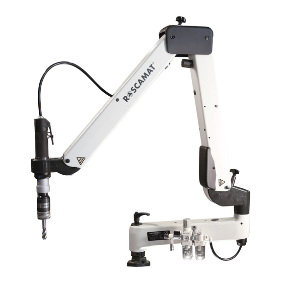
OPERATOR'S
MANUAL
Range
ROSCAMAT-500
Serial no.
Machine no.
Model
Year of
manufacture
Polígono Industrial Pla dels Vinyats, B – 08250 Sant Joan de Vilatorrada(Barcelona) Spain
+34 93 876.42.42 / +34 93 876.43.59
+34 93 876.77.38 / +34 93 876.40.44
E-mail :comercial@tecnospiromt.com – http://www.tecnospiromt.com
Advertisement

Related Manuals for Tecnospiro ROSCAMAT-500 Series

Summary of Contents for Tecnospiro ROSCAMAT-500 Series
- Page 1 OPERATOR’S MANUAL Range ROSCAMAT-500 Serial no. Machine no. Model Year of manufacture Polígono Industrial Pla dels Vinyats, B – 08250 Sant Joan de Vilatorrada(Barcelona) Spain +34 93 876.42.42 / +34 93 876.43.59 +34 93 876.77.38 / +34 93 876.40.44 E-mail :comercial@tecnospiromt.com –...
-
Page 2: Table Of Contents
CONTENTS Page nr Introduction ........Description R-500 RH ....... Working areas R-500 RH ..Description R-500 ......Working areas R-500 ....Description R-500 (C-26 N) ....Working areas R-500 (C-26 N) ..Description ........Installation ........Verification ......Operation ......... Anomalies ....... -
Page 3: Introduction
INTRODUCTION Dear customer: We wish to take this opportunity to thank you for choosing a “ROSCAMAT” tapping machine to produce quality threads ans associated operations. This operation’s manual is given to you so that by careful reading of its contents, it will be enable you to maintain its reliability and performance for long-life. -
Page 4: Description R-500 Rh
DESCRIPTION MACHINE ROSCAMAT-500 RH 1. MOTOR 2. FRONT BELLOW 3. TILTING ARMS 4. REAR BELLOW The basic machine consists of a 5. ARM LOCKING KNOB radial parallelogram, plus two pendular 6. RADIAL ARM parallelograms which are balanced by 7. AIR INLET SPIGOT pneumatic springs and a two-rotation 8. -
Page 5: Working Areas R-500 Rh
WORKING AREAS ROSCAMAT-500 RH... -
Page 6: Description R-500
DESCRIPTION MACHINE ROSCAMAT-500 1. MOTOR 2. AIR PIPE The basic machine consists of a radial 3. UPPER HAT arm, plus two pendular parallelograms 4. FRONT DAMPER REGULATION which are balanced by pneumatic HANDWHEEL springs. This group fixes the motor head 5. -
Page 7: Working Areas R-500
WORKING AREAS ROSCAMAT-500... -
Page 8: Description R-500 (C-26 N)
DESCRIPCTION MACHINE ROSCAMAT-500 (C-26 N) The ROSCAMAT-500 can be supplied with an articulated head (C-26 N). This bracket of easy handling can be set in four different positions 90º apart. Orientable head: 1.- Handle 2.- Milled nut Vertical operations: ... -
Page 9: Working Areas R-500 (C-26 N)
WORKING AREAS ROSCAMAT-500 (C-26 N) -
Page 10: Description
DESCRIPTION PNEUMATIC MOTOR TS-VIII 1.- Starting lever 2.- Reversing button 3.- Motor Head 4.- Module change slide collar 5.- Module 6.- Quick change (module) 7.- Tapholder with clutch REGULATING FILTER UNIT AIR LUBRICATION 1b.- Pressure regulator 2b.- Flow rate regulating valve 3b.- Pressure gauge 4b.- Reservoir (condensed water) 5b.- Drain pipe (WATER) - Page 11 DESCRIPTION AUTOMATIC TAP LUBRICATOR EQUIPMENT (E) 1.- Filling cap 2.- Drain screw 3.- Regulation valve 4.- Articulated pipe The machines of the model ROSCAMAT 500 E / 500 (C26 N) E /500 RH E, incorporate an automatic tap lubrication system. The oil reservoir is arranged inside the radial arm and is connected to an innerly arranged hydraulic cylinder.
-
Page 12: Installation
INSTALLATION Mount the machine base plate on to the working table by means of three M8 screws or the clamp. Fill up the reservoir (6b, page 10) with lubricating oil SAE-10. The air connection is carried out by means of a notched connections (17, page 4 y 14, page 6 ) located on the machine base. -
Page 13: Verification
INSTALLATION VERIFICATION Once the machine has been connected to the main, have to be checked: Supply pressure: 6-8 bar for full power The pressure gauge reading can drop 0,5 maximum 1,5 bar when the motor is started (if a drop greater than 2 bar is noticed, this means that the supply flow rate is not sufficient). -
Page 14: Operation
OPERATION 1. Turn the slide collar (4, page 10) to the left, insert the module and turn the slide collar to the right. 2. Regulate the arm balance for the 90 and 170 modules. 3. Insert the tapholder in the quick change of the module. 4. -
Page 15: Anomalies
OPERATION ANOMALIES Slipping clutch type tapholders. The clutch slips and the tap cannot be turned. 1. Clutch slackness. Clutch adjustment (page 15) 2. No tools lubrication. Use cutting oil. 3. Inappropriate tap for the material to machine. Use the correct tap. (page 16). -
Page 16: Technical Data
TECHNICAL DATA TURNING TORQUE (Nm) FOR THREADING Metric thread Steel > 100 Kg. Steel 80-100 Kg. Steel < 80Kg. Aluminium Cast Iron MACHINE TAPS Helical-flute tap. Blind hole Lubrication Straight-flute tap with helical Through hole feed-in Rake angle 8-10. Cutting oil with additive. Steel >... - Page 17 TECHNICAL DATA R-500 RH R-500 Pneumatic motor: Power 730 W. 730 W. Consumption 300-900 l/m 300-900 l/m Machine weight 39 Kg. 27 Kg. Intake filter 5 U.m. 5 U.m. Noise level 78 db. 78 db. Machine colours Blue to RAL 5002 Fog grey to RAL 7035 (Pneumatic motor TS-VIII)
-
Page 18: Maintenance
MAINTENANCE Practically the only machine’s part that we can wear is the motor. Therefore its maintenance should be carried out very carefully, which means that the air supply must be in dry & clean condition. For this purpose, the following three points must be taken into account: Drain periodically the water collected in the left air treatment unit cup by pressing the relief knob (5b, page 10). -
Page 19: Repairs
MAINTENANCE REPAIRS EXHAUST FILTER (REPLACEMENT) Ref. 40202304 1. Close the flow rate regulating valve situated on the left-hand side of the filtering unit (2b, page 10) and actuate the motor starting lever. 2. Take out the intake tube and the reversing button (1, 4). - Page 20 MAINTENANCE REPAIRS PRESSURE GAUGE (REPLACEMENT) Ref. NH40516 1. Close the flow control valve (2b, page 10), and actuate the motor lever in order to expel the compressed air from the inside of the motor 2. Turn the manometer "sight" to the right, and unscrew the two screws securing the manometer to the FRL air servicing unit.
- Page 21 MAINTENANCE REPAIRS CLEAN and BLOW OFF all parts before doing the assembly. 6. Lubricate the motor plates and both ball bearings with SAE 10 oil. 7. Place the motor plates in their seatings, the motor stator in its right position, install the upper head together with its ball bearing and mount the “seeger”...
- Page 22 MAINTENANCE REPAIRS MULTIPOSICION HEAD (ADJUSTMENT) In the event that the articulated head doesn’t perfectly lock its movement or if on the contrary, it moves with difficulty on its idle position, it should be adjusted. If the coupling on the motor side is to be adjusted, then the motor should be removed from the articulated head or if the coupling to be adjust is the other one, remove the plastic cap.
- Page 23 MAINTENANCE REPAIRS REAR DAMPER (SUBSTITUTION) Remove the bellows ((4, page 6) and (7, page 6)) Remove the screw that butts against the regulating fork. Pull out the nylon part that butts against the arm top. With the arm in its vertical position, turn the knob counterclockwise in order to release the damper up to it becomes completely loose.
-
Page 24: Operation R-500 Rh
OPERATION ROSCAMAT 500 RH The machine can work in two different ways: vertical or non-vertical (any position). VERTICAL THREADING 1- Unlock the arm, button (16, page 4). 2- Insert the sensing plate. 3- Unlock the head through lever (17, page 4). 4- Apply the plate to work surface. - Page 25 OPERATION ROSCAMAT 500 RH (fig.a) (fig.b)
- Page 26 OPERATION ROSCAMAT 500 RH For vertical threading with the modules 90 and 170, you should tighten the brake lever (15, page 4) For working with the modules 90 and 170 in non-vertical position, you should consider certain head position limitations (see fig.a, page 25) When using the modules 90 and 170 in non-vertical position, the motor direction should be maintained within the range shown in the drawing a, page It is helpful to place the machine in an approximately centered position with...
-
Page 27: Spare Parts List
MAINTENANCE SPARE PARTS LIST REPLACEMENT ARM PARTS (R-500 RH y R-500 models ) AC0 200 56 Damper regulating handwheel AC0 903 36 Bellow 262 048 04 Double Bellow Front damper regulating fork 262 019 B5 262 019 C5 Rear damper regulating fork 262 010 A3 Front damper abutment 512 006 03... - Page 28 MAINTENANCE SPARE PARTS LIST MOTOR REPLACEMENT PARTS 402 001 02 Pneumatic motor TS-VIII 402 017 03 Rotor 402 017 05 Rotor assembly Rotor cassing 402 019 03 402 011 05 Gearbox assembly 402 012 03 Module change slide collar 402 014 04 Planetary gear train 402 022 04 Raccord...
- Page 29 MAINTENANCE SPARE PARTS LIST AUTOMATIC LUBRICATION REPLACEMENT PARTS Lubrication pump 404 001 04 Oil tank assembly 904 002 04 520 012 04 Oil tank assembly* ACO 404 06 Filler plug CL0 505 66 Drain plug 311 025 04 Articulated pipe and lubrication nipple Raccord and lubrication pipe kit 520 015 04 Control knob...
- Page 30 REPLACEMENT ARM PARTS (R-500 y R-500 RH models) Bellow Double bellow Damper reg. handwheel Ref. AC0 903 36 Ref. 262 048 04 Ref. AC0 200 56 Dampers regulating fork Damper abutments Arm abutments Front Ref. 262 019 B5 Front Ref. 262 010 A3 Ref.
- Page 31 REPLACEMENT ARM PARTS (R-500 & R-500 RH models) Spindle arm with screws Spindle of the arm damper Spindle of the fork damper Ref. 301 040 04 Ref. 262 005 03 Ref. 262 008 03 REPLACEMENT ARM PARTS (Only R-500 RH model) Handle (Multipos.
- Page 32 REPLACEMENT ARM PARTS (Only R-500 model) Machine base Radial Arm Main axis Ref. 251 015 04 Ref. 901 007 05 Ref. 251 017 04 Vertical head C-24 Flat motor head C-25 Orientable head C-26 N Ref. 252 003 A4 Ref. CC0 002 04 Ref.
- Page 33 MOTOR REPLACEMENT PARTS Pneumatic motor TS-VIII Rotor Rotor assembly Ref. 402 001 02 Ref. 402 017 03 Ref. 402 017 05 Rotor cassing Gearbox assembly Module change slide collar Ref. 402 019 03 Ref. 402 011 05 Ref. 402 012 03 Planetary gear train Raccord Motor framework...
- Page 34 MOTOR REPLACEMENT PARTS Exhaust filter Exhaust cover Inversion button Ref. 402 023 04 Ref. 402 002 03 Ref. AC0 404 76 Splitter joint pack Ref. NH0 205 14...
- Page 35 PNEUMATIC REPLACEMENT PARTS Elbow fitting 90º 3/8-10 Ref. NH0 906 06 Notched spigot 3/8 –12 Elbow fitting 90º 1/4-10 Straight raccord 3/8-10 Ref. NH0 907 96 Ref. NH0 902 86 Ref. NH0 906 96 Flowrate regulating valve Intake filter Pressure gauge Ref.
- Page 36 AUTOMATIC LUBRICATION REPLACEMENT PARTS Oil tank assembly Filler plug Ref. 904 002 04 (R-500) Lubrication pump Ref. ACO 404 06 Ref. 520 012 04 *(R-500 RH) Ref. 404 001 04 Drain plug Articulated pipe & Racc.& lubrication Ref. CL0 505 66 lubr.
- Page 37 ACCESSORIES REPLACEMENT PARTS Trolley & Table wheel 1.500x850 & 850x850 Setting piece Quick-change Ref. AC0 803 76 ( without brake Ref. (19/1): 263 002 03 (Modules 90, 170) Ref. AC0 803 86 (with brake) Ref. (31/2): 513 003 03 Ref. AC0 900 46 Quick-change (Modules Drill chuck Ø10 Elevator...
-
Page 38: Standard Products Range
STANDARD PRODUCTS RANGE SUPPORTS · Clamping device: For mounting the machine on to any table or workbench. Ref. BR1 001 00 DETACHABLE TABLES Measures: 850 x 850 x 850 Weight: 74 Kg. Maximum weight on table: 200 Provided with: ·... - Page 39 STANDARD PRODUCTS RANGE TROLLEY WITH COLUMN For moving the working unit. The column used to fix the machine by means of 4 metallic dowels. Provided with 4 pivoted wheels (2 with brake) Measures: 700 x 700 x 940 Weight: Ref.
- Page 40 STANDARD PRODUCTS RANGE QUICK-CHANGE TOOLHOLDER A wide range of tapholders, all of them with clutch and without it, apart from other quick holding mixtures for different tools, duch as drills, sinking tools, threading dies, socket wrenches, etc, are avaialable. ·...
- Page 41 STANDARD PRODUCTS RANGE THREADING DIE HOLDER For die threading. Capacity range M5-M20. LONG THREADING DIE HOLDER For guided die threading Capacity range M6 a M12. QUICK CHANGE EXTENSION To separate 80 mm, tool from the head member and gain access to difficult areas.
- Page 42 STANDARD PRODUCTS RANGE MODULAR SYSTEM Driven from a single motor, seven different speed modules are available with their relevant power torques. The seven quick-change speed modules provide the speed and torque for each threading type, from M3 to M24 threads, getting this way important time and energy saving.
- Page 43 CERTIFICATE “CE” OF CONFORMANCE Company : TECNOSPIRO Machine Tool SL Addres: POL.IND. PLA DELS VINYATS, B City: SANT JOAN DE VILATORRADA Country: ESPAÑA hereby certify, on our own responsibility that the machine Brand : ROSCAMAT Type : Range 500 RH Series nr.
Need help?
Do you have a question about the ROSCAMAT-500 Series and is the answer not in the manual?
Questions and answers