Table of Contents
Advertisement
Quick Links
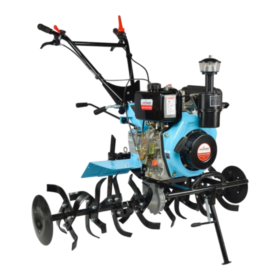
AGRIMATE ROTARY TILLER
AM-MPT-1100-6D-M
(MANUAL)
Power Weeder / Rotary Weeder / Cultivator
OPERATION AND MAINTENANCE MANUAL
DISCLAIMER: DUE TO CONSTANT UPGRADATION, FEATURES AND SPECIFICATIONS ARE
SUBJECT TO CHANGE WITHOUT NOTICE
BEFORE OPERATING THIS MACHINE,
PLEASE READ THESE INSTRUCTIONS CAREFULLY
Advertisement
Table of Contents

Related Manuals for Agrimate AM-MPT-1100-6D


Summary of Contents for Agrimate AM-MPT-1100-6D
- Page 1 AGRIMATE ROTARY TILLER AM-MPT-1100-6D-M (MANUAL) Power Weeder / Rotary Weeder / Cultivator OPERATION AND MAINTENANCE MANUAL DISCLAIMER: DUE TO CONSTANT UPGRADATION, FEATURES AND SPECIFICATIONS ARE SUBJECT TO CHANGE WITHOUT NOTICE BEFORE OPERATING THIS MACHINE, PLEASE READ THESE INSTRUCTIONS CAREFULLY...
-
Page 2: Safety Information
Something about this manual Rotary Tiller/Power Weeder/Cultivator Thank you for choosing our Rotary Tiller/Power • This manual contains about operation and maintenance of Diesel Weeder/Cultivator . • All contents in this manual are based on the latest information when the manual is printed. •... - Page 3 Contents Chapter 1 Profile of Rotary Tiller/Power Weeder/Cultivator specification general pictures Chapter 2 Main function of Rotary Tiller/Power Weeder/Cultivator rotary tillage ditching and ridge forming short distance transportation multifunctional work Chapter 3 Operation and application of Rotary Tiller/Power Weeder/Cultivator 3 unpacking assembly installation and adjustment of cables checking and refueling...
-
Page 4: Chapter 1 - Profile Of Rotary Tiller/Power Weeder/Cultivator
Chapter 1 - Profile of Rotary Tiller/Power Weeder/Cultivator Engine Specifications Engine Model AM178F Type Single Cylinder, Vertical, Diesel Engine-4S, Air Cooled Starting recoil start Fuel Diesel Engine Oil Capacity(Litre) Capacity of Fuel tank (Litre) Valve Rated Power-kw/HP/RPM 4kw/5.4hp/3600 Displacement (cubic capacity), (cm3) Bore/Stroke (mm) 78×62 Max. -
Page 5: Chapter 2 - Main Function Of Rotary Tiller/Power Weeder/Cultivator
Chapter 2 - Main function of Rotary Tiller/Power Weeder/Cultivator Weeding blades assy: Weeding blades assy components are installed on both sides of the driving shaft of Rotary Tiller/Power Weeder/Cultivator running gear. Tighten the shaft with two bolts M8×55. Then the Rotary Tiller/Power Weeder/Cultivator can work. -
Page 6: Chapter 3 - Operation And Application Of Rotary Tiller/Power Weeder/Cultivator
Chapter 3 - Operation and application of Rotary Tiller/Power Weeder/Cultivator Fix the body of mini Weeder, install running wheels on both sides of hexagonal shaft and fix the wheels with 2 bolts M8×55, 2 nuts M8. Handle bar installation: turn the two fluted discs on the handlebar to right with the fluted discs on both sides of the disc plate. -
Page 7: Checking And Refueling
gun cable adjustment (look at picture7) Diagram • Turn gun switch to the fastest position. • Thread the steel wire-rope of the gun into the pole and plug of regulation panel of the diesel engine gun. • Fasten the steel wire-rope and fix the screw. •... - Page 8 • Refuel air cleaner with oil, take away the synthetic glass cover tent below the cleaner, and refuel 0.1L num.20 oil. • Choose diesel engine oil according to the working environment(Picture9) Refuel the oil tank with num.0, num.-10 or num.-20 light oil (please refer to the diesel engine instruction).
- Page 9 Fast gear • Hold the clutch bar with left hand to open the clutch. • Push the shift lever to the front with right hand, meanwhile, pay attention if it is in the fast position, then hold the bar with right hand(attention: do not hold the backshift bar) •...
- Page 10 When ditching, you should take down shift lever, install the ditcher and adjust its depth and height. After finishing these, you can do ditching work. (look at picture3) Range of ditching scope: 14cm-40cm Range of ditching depth: 11cm-25cm Short-distance transportation Install forearm of Rotary Tiller/Power Weeder/Cultivator case on the drug bar of running gear and install wheels on the driving shift of the running gear.
- Page 11 2. RUNNING IN FOR 5 MINS AFTER FIRST START. Running with low speed and low load before the engine gets hot.Avoid running with high speed and full load, or low speed and no load. 3. AVOID RUNNING WITH OVERLOAD. During break-in period, the engine can't run with full load, but can run with 3000rpm and 50% load. 4.
-
Page 12: Safety Instructions
Whether the exhaust is normal? iii. Whether the engine gives out white or black smoke continuously? If any of the above phenomena is detected, stop the engine immediately and contact the nearby dealer. X. Methods of Starting the Rotary Tiller/Power Weeder/Cultivator Starting by Hand: •... - Page 13 • Only operator with knowledge of machine and its operations must be permitted to operate Agricultrual Weeder • Must stop engine before refueling, and refuel in good ventilation place • Must clean and spilled or over flown fuel of the Agricultrual Weeder •...
-
Page 14: Chapter 4 - Maintenance Of Rotary Tiller/Power Weeder/Cultivator
Chapter 4 - Maintenance of Rotary Tiller/Power Weeder/Cultivator Due to rotary situation, abrasion and load change of Rotary Tiller/Power Weeder/Cultivator, bolts will become loose and parts will be worn during the work. These changes will destroy the proper working state of Rotary Tiller/Power Weeder/Cultivator, create abnormal fitting clearance, degrade output of diesel engine, increase oil consumption, lead to the maladjustment of spare parts, increase malfunction of Rotary Tiller/Power Weeder/Cultivator. - Page 15 13. Invite special technician to check friction plate and clutch. As for the maintenance of diesel engine, please refer to its instruction. Technical maintenance table of Rotary Tiller/Power Weeder/Cultivator(mark”0” indicates the maintenance contents) Working intervals Every Work with Work for Work for 3 Every year Per 2 years...
-
Page 16: Chapter 5 - Debugging Method Of Rotary Tiller/Power Weeder/Cultivator
Chapter 5 - Debugging method of Rotary Tiller/Power Weeder/Cultivator Debugging method of bevel gear assy: When bevel gear drives abnormally with loud noise, you should check and debug it immediately. The debugging methods are as follows: Bevel gear clearance debugging of gear box(look at picture10) ∆... - Page 17 Debugging method of gun cable When revolving the gun switch and finding accelerating and decelerating function of the diesel engine is not good, you should debug the gun cable. As for the method, please refer to chapter3. 1. Revolve the gun switches for twice or three times and check the accelerating ! Attention: and decelerating function of diesel engine.
-
Page 18: Chapter 6 - Troubleshooting
Chapter 6 - Troubleshooting Troubleshooting of diesel engine (refer to the diesel engine instruction) Troubleshooting of clutch (attention: never take part the clutch assy just by yourself. Table 6 Phenomenon Reason Solution Malfunction of clutch Repair or change handlebar Damage of clutch cable change Readjust cable or change Misadjustment of clutch fork... - Page 19 Troubleshooting of gear-box Table 7 Phenomenon Reason Solution Take away screws and key Fast, slow and neutral shift can Screws and round nuts behind sleeve behind the main shaft; not be positioned the shaft become loose reinstall key sleeve and screws after tightening the round nuts Auxiliary brick is severely change auxiliary brick...
- Page 20 Bolts behind the backshift Tighten the bolts shaft become loose Backshift shaft becomes loose The backshift shaft and case Change are not well fitted Bevel gear shaft and backshift Change shaft become curved Gear noise is too loud Gears are heavily fretted Change gear Bevel gear shaft and backshift Change...
- Page 21 Troubleshooting of running gear Table 8 Phenomenon Reason Solution Gear noise is too loud Gear is heavily fretted or Readjust or change the gear repaired improperly Gear is seized Gear installation is incorrect Reinstall Overheat Lube in the case is insufficient Refuel lube according to the requirement Gear side clearance is too...
- Page 22 easily-damaged parts of Rotary Tiller/Power Weeder/Cultivator Number Name Assy Clutch cable Handle frame assy Back shift clutch Handle frame assy Gun clutch Handle frame assy Gun switch Handle frame assy Rubber handlebar Handle frame assy Rubber sleeve Shift lever, tighten handlebar Oil seal45×62×68 Gear box assy Oil seal25×40×7...
-
Page 23: Chapter 7 - Instruction Table Of Attaching Tools
Chapter 7 - Instruction table of attaching tools Table 10 Number Name Unit Usage Rotary Weeding wheels of paddy field Weeding in paddy field Water pumping device(centrifugal water Water pumping pump3-stroke) Ditcher Ditching Chapter 8 - Bearings of Rotary Tiller/Power Weeder/Cultivator Table 11 Number Model... - Page 24 Rotary Tiller/Power Weeder/Cultivator New Six Shifts Operating Guide 1. Gear operation instruction a. Gear schematic drawingt deputy shifting gear pictures picture deputy shifting (high) deputy shifting (low) first gear neutral second gear reverse gear b. Gear tachometer1-1 Shifts deputy shifting revolving speed (r/min) (high) speed (km/h)
- Page 25 2. Output clutch handle instructions clutch claw + machine operating pictures PTO output clutch release PTO output clutch close...
- Page 26 SPARE PARTS DIAGRAM OF AM-MPT-1100-6D HANDLE CONTROL PARTS-A...
- Page 27 SPARE PARTS LIST OF AM-MPT-1100-6D Parts No. Description Parts No. Description AM-MPT-1100-6T-A1 Handle Grip AM-MPT-1100-6T-A22 Tray, Gear AM-MPT-1100-6T-A2 Shut Down Switch Comp AM-MPT-1100-6T-A23 High And Low Lock Comp AM-MPT-1100-6T-A3 Bolt M6×20 AM-MPT-1100-6T-A24 Shift Lever AM-MPT-1100-6T-A4 Nut M6 AM-MPT-1100-6T-A25 Handle Seat Comp...
- Page 28 SPARE PARTS DIAGRAM OF AM-MPT-1100-6D SHIFT GEAR PARTS-B...
- Page 29 SPARE PARTS LIST OF AM-MPT-1100-6D Parts No. Description Parts No. Description AM-MPT-1100-6T-B1 Sheath, Shift rod AM-MPT-1100-6T-B27 Spring washer 6 AM-MPT-1100-6T-B2 Pin 6×40, Shift rod AM-MPT-1100-6T-B28 Hex bolts M6×20 Protec cover, principal AM-MPT-1100-6T-B3 Clip AM-MPT-1100-6T-B29 AM-MPT-1100-6T-B4 Bush Shift axes AM-MPT-1100-6T-B30 Screw M6×20 AM-MPT-1100-6T-B5 O-ring 11.2×2.65...
- Page 30 SPARE PARTS LIST OF AM-MPT-1100-6D Parts No. Description Parts No. Description Double gear, AM-MPT-1100-6T-B75 Sawtooth locked gasket AM-MPT-1100-6T-B50 countershaf AM-MPT-1100-6T-B76 Flange bolt M8×20 AM-MPT-1100-6T-B51 Gasket, countershaft AM-MPT-1100-6T-B77 Axletree 6207 AM-MPT-1100-6T-B52 Sheath, countershaft AM-MPT-1100-6T-B78 Core comp, clutch Thrust ball bearing AM-MPT-1100-6T-B53...
- Page 31 SPARE PARTS DIAGRAM & PARTS LIST OF AM-MPT-1100-6D TRANSMISSION CASE PARTS-C Parts No. Description Parts No. Description AM-MPT-1100-6T-C1 Nut M12 AM-MPT-1100-6T-C13 Cover, output axes AM-MPT-1100-6T-C2 Splitpin 2.5×22 AM-MPT-1100-6T-C14 Gasket 60×45.5×0.1 AM-MPT-1100-6T-C3 Spring washer 12 AM-MPT-1100-6T-C15 Cover, flange axes AM-MPT-1100-6T-C4 Driven umbrella gear...
- Page 32 SPARE PARTS DIAGRAM & PARTS LIST OF AM-MPT-1100-6D ROTARY TILLER PARTS - D Parts No. Description Parts No. Description AM-MPT-1100-6T-D1 Round plate(Optional) AM-MPT-1100-6T-D7 Blade(L) AM-MPT-1100-6T-D2 Counter tube AM-MPT-1100-6T-D8 Blade(R) AM-MPT-1100-6T-D3 Bolt M8×55 AM-MPT-1100-6T-D9 Hex bolt M10×35 AM-MPT-1100-6T-D4 Spring washer 8...
- Page 33 SPARE PARTS DIAGRAM & PARTS LIST OF AM-MPT-1100-6D LAMBDOIDAL WHEEL PARTS - E Parts No. Description Parts No. Description AM-MPT-1100-6T-E1 Nut M10 AM-MPT-1100-6T-E6 Inner tube AM-MPT-1100-6T-E2 Spring washer 10 AM-MPT-1100-6T-E7 Outer rubber tyre 4.00-8 AM-MPT-1100-6T-E3 Washer 10 AM-MPT-1100-6T-E8 Spoke ( L )
- Page 34 SPARE PARTS DIAGRAM OF AM-MPT-1100-6D JOINT PARTS - F...
- Page 35 SPARE PARTS LIST OF AM-MPT-1100-6D Parts No. Description Parts No. Description Diesel engine comp AM-MPT-1100-6T-F28 Bumper support AM-MPT-1100-6T-F1 Dieselengine AM-MPT-1100-6T-F29 Spring comp(Elect AM-MPT-1100-6T-F30 Falnge bolt M10×30 AM-MPT-1100-6T-F2 Flange gasket AM-MPT-1100-6T-F31 Bumper comp AM-MPT-1100-6T-F3 Flange AM-MPT-1100-6T-F32 Support frame, engine AM-MPT-1100-6T-F4 Bolt M12×1.25×25 AM-MPT-1100-6T-F33 Bolts, M8×12...
- Page 36 SPARE PARTS DIAGRAM & PARTS LIST OF AM-MPT-1100-6D Parts No. Description Parts No. Description AM-MPT-1100-6T-G1 Shift Gears AM-MPT-1100-6T-G22 Nut M8 AM-MPT-1100-6T-G2 Split ring 9 AM-MPT-1100-6T-G23 spring Clip Φ25 AM-MPT-1100-6T-G3 Sheath, Shift rod AM-MPT-1100-6T-G24 Grip Φ25 AM-MPT-1100-6T-G4 PTO Higer B AM-MPT-1100-6T-G25...
- Page 37 SPARE PARTS DIAGRAM & PARTS LIST OF AM-MPT-1100-6D HANDLE CONTROL PARTS - H Parts No. Description Parts No. Description AM-MPT-1100-6T-H1 Handle seat-I AM-MPT-1100-6T-H13 Throttle Switch Comp(φ25) Handle seat wear-proof AM-MPT-1100-6T-H14 Pin 1.6x20 AM-MPT-1100-6T-H2 casing AM-MPT-1100-6T-H15 Pin 7×24 AM-MPT-1100-6T-H3 Handle seat -II AM-MPT-1100-6T-H16 Cable joint 10×24...
- Page 38 SPARE PARTS DIAGRAM OF AM-MPT-1100-6D SIX SHIFT GEARS PARTS-FRONT - A...
- Page 39 SPARE PARTS LIST OF AM-MPT-1100-6D Parts No. Description Parts No. Description Gasket AM-MPT-1100-TGB-A1 Gearbox,Front AM-MPT-1100-TGB-A19 15.5×26×2.6,clutch AM-MPT-1100-TGB-A2 ø8 steel ball AM-MPT-1100-TGB-A20 Ball bearing 6202 Washer Φ8 AM-MPT-1100-TGB-A3 Gear-Shifting spring AM-MPT-1100-TGB-A21 Serrated lock washers AM-MPT-1100-TGB-A4 Hexagon srew M10X35 AM-MPT-1100-TGB-A22 Φ8 Hexagon flange bolts...
- Page 40 SPARE PARTS DIAGRAM OF AM-MPT-1100-6D GEARBOX-END COVER - B...
- Page 41 SPARE PARTS LIST OF AM-MPT-1100-6D Part No. Description Part No. Description AM-MPT-1100-TGB-B1 End cover AM-MPT-1100-TGB-B34 Gear-shift fork AM-MPT-1100-TGB-B2 Cylindrical pin 5X10 AM-MPT-1100-TGB-B35 Spacer 20.5×25×11.5 AM-MPT-1100-TGB-B3 Washer 10.5×22×4 AM-MPT-1100-TGB-B36 Ball bearing KT22×26×13 Spring washer Φ10 AM-MPT-1100-TGB-B4 AM-MPT-1100-TGB-B37 Adjusting washer AM-MPT-1100-TGB-B5 Hexagon bolt M10X40 22×32×2...
- Page 42 SPARE PARTS DIAGRAM OF AM-MPT-1100-6D CO-BOX COMPONENTS - C...
- Page 43 SPARE PARTS LIST OF AM-MPT-1100-6D Parts No. Description AM-MPT-1100-TCB-C1 Gasket, End cover 1 AM-MPT-1100-TCB-C2 Gear B, Principal axles 1 AM-MPT-1100-TCB-C3 Abrasion resistant washer 14.5×23×2 AM-MPT-1100-TCB-C4 Ball bearing K14×18×13 Locating pin Φ8×14 AM-MPT-1100-TCB-C5 Flat washer Φ10 AM-MPT-1100-TCB-C6 Spring washer Φ10 AM-MPT-1100-TCB-C7...
- Page 44 ENGINE PART DIAGRAM OF AM-MPT-1100-6D CRANKCASE ASSY - A...
- Page 45 ENGINE PARTS LIST OF AM-MPT-1100-6D Part No. Description Part No. Description Drain Plug/Crankshaft AM-1100-178F-A24 Govemor AM-1100-178F-A1 Plug Vibration Isolation AM-1100-178F-A25 AM-1100-178F-A2 Oil Plug Seal Assy Cushion Block AM-1100-178F-A3 Oil Seal Sg30*45*8 AM-1100-178F-A26 Shrath Cylinder Block.(Manual) AM-1100-178F-A27 Bolt M6*20 AM-1100-178F-A4 Cylinder Head Stud/ Cylinder Block.(Key start)
- Page 46 ENGINE PART DIAGRAM & PARTS LIST OF AM-MPT-1100-6D CYLINDER HEAD ASSY - B Part No. Description Part No. Description AM-1100-178F-B1 Air Intake Gasket AM-1100-178F-B15 Rock Arm Assy AM-1100- AM-1100-178F-B16 Cotter Cylinder Head 178F-B2/5/6/10 AM-1100-178F-B17 Valve Adjusting Plate AM-1100-178F-B3 Intake Valve...
- Page 47 ENGINE PART DIAGRAM & PARTS LIST OF AM-MPT-1100-6D CYLINDER HEAD COVER - C Part No. Description AM-1100-178F-C3 Bonnet Assy AM-1100-178F-C6 Bonner Gasket AM-1100-178F-C10 Bolt M6*55 PISTON + CONNECTING ASSY - D Part No. Description AM-1100-178F-D1 Ring Set AM-1100-178F-D2 Piston AM-1100-178F-D3...
- Page 48 ENGINE PART DIAGRAM & PARTS LIST OF AM-MPT-1100-6D CRANKSHAFT + FLYWHEEL - E Part No. Description Part No. Description AM-1100-178F-E1 Ball Bearing 6202/P5 Drive Gear Of Balance AM-1100-178F-E13 Shsft AM-1100-178F-E2 Balancer Shaft AM-1100-178F-E14 Flywheel Ring Geat AM-1100-178F-E3 Key 5×7 AM-1100-178F-E15...
- Page 49 ENGINE PART DIAGRAM & PARTS LIST OF AM-MPT-1100-6D CAMSHAFT ASSY - F Part No. Description AM-1100-178F-F1 Valve Rod Assy AM-1100-178F-F2 Valve Tappet AM-1100-178F-F3 Camshaft Timing Gear AM-1100-178F-F4 Key 5*14 AM-1100-178F-F5 Camshaft FAN COVER - G Part No. Description AM-1100-178F-G1 Shock Absorber Seat...
- Page 50 ENGINE PART DIAGRAM & PARTS LIST OF AM-MPT-1100-6D MUFFLER ASSY - H Part No. Description AM-1100-178F-H1 Silencer Assy AM-1100-178F-H2 Nut 8 AM-1100-178F-H3 Spring Washer 6 AM-1100-178F-H4 Washer 8 AM-1100-178F-H5 Bolt M6*14 Part No. Description LUBRICATING SYSTEM - J AM-1100-178F-J1 Bolt M6*12...
- Page 51 ENGINE PART DIAGRAM & PARTS LIST OF AM-MPT-1100-6D FUEL SYSTEM - K Part No. Description Part No. Description AM-1100-178F-K1 Bolt M8×45 AM-1100-178F-K12 Nut 6 AM-1100-178F-K2 Upper Stay Bolt AM-1100-178F-K13 Fuel Tank Gock Assy AM-1100-178F-K3 Washer 8 AM-1100-178F-K14 O-Ring 13.2*1.8 AM-1100-178F-K4...
- Page 52 ENGINE PART DIAGRAM & PARTS LIST OF AM-MPT-1100-6D SPEED CONTROL SYSTEM - L Part No. Description Part No. Description AM-1100-178F-L1 Tappet 25.5 AM-1100-178F-L6 Governor Spring AM-1100-178F-L2 Lever Fork AM-1100-178F-L7 Fine Spring AM-1100-178F-L3 Oil Seal 8×14×4 AM-1100-178F-L8-1 Control Lever Assy AM-1100-178F-L4...
- Page 53 ENGINE PART DIAGRAM & PARTS LIST OF AM-MPT-1100-6D AIR CLEANER - M Part No. Description Part No. Description Intake Pipe/ Washer I AM-1100-178F-M7 AM-1100-178F-M1 Integration Air Filter Case AM-1100-178F-M8 Nut M6×12 AM-1100-178F-M2 O-Ring AM-1100-178F-M9 Air Cleaner Gasket AM-1100-178F-M3 Air Cleaner Element...
- Page 54 ENGINE PART DIAGRAM & PARTS LIST OF AM-MPT-1100-6D FUEL INJECTION PUMP - P Part No. Description Part No. Description Fuel Delvery Valve Forcing Washer AM-1100-178F-P1 Holder Pin2x6 AM-1100-178F-P2 Fuei Delhrery Valve Spring Fip Connecting Plate Fuel Oelivery Vahre Sheet Fuel Limiting Sheath...
- Page 55 ENGINE PART DIAGRAM & PARTS LIST OF AM-MPT-1100-6D RECOIL STARTER ASSY - Q Part No. Description Part No. Description AM-1100-178F-Q1 Nut M8 AM-1100-178F-Q8 Starter Reel AM-1100-178F-Q2 Friction Plate AM-1100-178F-Q9 Spiral Spring AM-1100-178F-Q3 Friction Reel AM-1100-178F-Q10 Outer Case Assy AM-1100-178F-Q4 Spring Cover...
-
Page 56: Inspection And Maintenance
INSPECTION & MAINTENANCE For safety use, make sure the machine is cleaned every three-months. Before working, make sure to inspect the filter and the nozzle,and ensure there is no impurity. After working, make sure there is no water in the pump and the hose. If the machine needs to be repaired in the guarantee period, please return the machine to the shop. - Page 57 Warranty Card CUSTOMER COPY Date Date of Delivery Purchaser’s Name & Address Dealer’s Office Seal Product Name AM-MPT-1100-6D-M Rotary Tiller / Power Weeder / (MANUAL) Rotary Weeder / Cultivator Dealer Sign Product Serial No. Customer Sign. Invoice / DN No.
- Page 58 1. LIMITED WARRANTY PERIOD : For a period of six months from the date of Sale / delivery of the product which ever is earlier. 2. LIMITED WARRANTY OBLIGATION : Replacement of defective part(s) by authorized dealer are free of charges. If found defective by reasons of defective material / poor workmanship, parts will be replaced and there will be no value re-imbursement.
- Page 59 1st Free Service Coupon ISO 9001-2015 CERTIFIED COMPANY FREE SERVICE COUPON (30 Days / 20 hrs (Which ever is earlier) Model Serial Number AM-MPT-1100-6D-M (MANUAL) Rotary Tiller / Power Weeder / Rotary Weeder / Cultivator PDI Date Service No. Purchase bill no. Date Dealer’s Office Seal...
- Page 60 Small Maintenance. Big Savings. Small Maintenance. Big Savings. Small Maintenance. Big Savings.
- Page 61 Do’s Don’ts • Always read the instruction manual supplied along with the equipments and understand the correct installation and operating procedures before attempting to use the equipments. • It is important to use the personal protection equipments such as head helmet with visor, ear defenders, goggles, safety gloves, cut resistant shoes, trousers and jackets while operating potentially dangerous machines.
- Page 62 Agrimate Army For Pest Control ANY WHERE - ANY TIME - ANY CROP RATNAGIRI IMPEX PVT., LTD. Annapurna House, #1 / 1G, 7th Cross, New Guddadahalli Mysore Road, Bangalore - 560 026 Customer Care: 1800-425-3036 Email: info@ratnagiriimpex.com www.ratnagiriimpex.com AN ISO 9001:2015 CERTIFIED COMPANY...
Need help?
Do you have a question about the AM-MPT-1100-6D and is the answer not in the manual?
Questions and answers