Advertisement
Quick Links
ASSEMBLY
INSTRUCTION
2.5 hrs
APPROXIMATE ASSEMBLY TIME
EXCLUDING GLUE SETTING TIME
8 m m
REQUIRED ASSEMBLY TOOLS
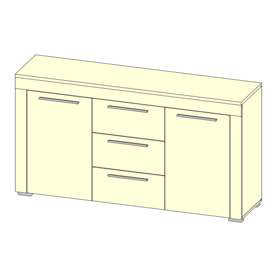
DESCRIPTION:
Type 84
NOVEDO
2 PERSON ASSEMBLY
1 6 0 0 m m
FLOOR AREA
2,5M X 2,5M
REQUIRED ASSEMBLY SPACE
M E A
S U R
E
ASSEMBLED DIMENSIONS
PACK 1
CONSISTS OF PARTS:
1,2,5,6,7,8,9,11,13
Fittings
PACK 2
CONSISTS OF PARTS:
3,4,10,12,14,17
CEILING HEIGHT
2,0M
1/15
Advertisement

Related Manuals for LV Furniture NOVEDO 84


Summary of Contents for LV Furniture NOVEDO 84
- Page 1 DESCRIPTION: ASSEMBLY Type 84 INSTRUCTION NOVEDO FLOOR AREA CEILING HEIGHT 2,5M X 2,5M 2,0M 2.5 hrs APPROXIMATE ASSEMBLY TIME 2 PERSON ASSEMBLY REQUIRED ASSEMBLY SPACE EXCLUDING GLUE SETTING TIME 8 m m M E A S U R REQUIRED ASSEMBLY TOOLS ASSEMBLED DIMENSIONS PACK 1 CONSISTS OF PARTS:...
- Page 2 PART LIST NO. PARTS LIST NO. PARTS LIST (1) LEFT SIDE PANEL (12) L/R DOOR (2) RIGHT SIDE PANEL (13) DRAWER FRONT (3) BOTTOM PANEL (14) DRAWER BOTTOM (4) TOP PANEL (17) DRAWER PANEL (5) LEFT DIVIDER (6) RIGHT DIVIDER (7) SHELF L/R BACK PANEL (9) BACK PANEL...
- Page 3 HARDWARE LIST 3,5x30mm 3x20mm 15x12mm 8x28mm SCREW SCREW SECURING CAM BOLT DOWEL SCREW COVER CAM LOCK BRACKET 3,5x13mm 4x40mm 6x9mm 6x9,5mm SCREW SQUARE NYLON FOOT HANDLE SCREW WPM SCREW GRUB SCREW 4x30mm GLUE SCREW METAL PLATE 3/15...
- Page 4 HARDWARE LIST 3x Left / 3x Right L=245 BALL RUNNER HINGE PLATE HINGE 3,5x13mm 4x35mm 5x16mm PLASTIC ANGLE DOWEL SHELF SUPPORT 3/15...
- Page 5 Top Tips before you start! Please check that all parts are present before you start the assembly of your furniture, as once assembled, the furniture is exempt from our home approval policy. For ease and speed of assembly, we recommend that before you commence each step of the assembly, that you identify all the parts required for that step.
- Page 6 SPECIAL TIPS FOR FITTING CAM-LOCKS AND CAM-PILLARS CAM-LOCK Align with long point of cross WHEN FITTING CAMS ENSURE STARTING POSITION IS CORRECT BEFORE YOU INSERT CONNECTING CAM-PILLAR TURN CLOCKWISE UNTILE SECURE WRONG CORRECT Pillar head needs to be in centre CAM-PILLAR Tighten until shoulder is flush with panel.
- Page 7 STEP 1 STEP 2 3,5x30mm 4x30mm SCREW HANDLE GLUE SCREW GLUE 7/15...
- Page 8 STEP 3 4x40mm SCREW NYLON FOOT CAM BOLT 180° 240mm 190mm 8/15...
- Page 9 STEP 4 3,5x13mm SQUARE SCREW HINGE PLATE STEP 5 15x12mm 8x28mm CAM LOCK DOWEL 9/12...
- Page 10 STEP 6 3x Left / 3x Right L=245 6x9,5mm 15x12mm 8x28mm BALL RUNNER GRUB SCREW DOWEL CAM LOCK 180° 180° 10/15...
- Page 11 STEP 7 STEP 8 11/15...
- Page 12 STEP 9 STEP 9 3,5x13mm 90° c a . 1 0 m SCREW HINGE 12/15...
- Page 13 STEP 9 3x20mm METAL PLATE SECURING SCREW BRACKET 3x20mm 13/15...
- Page 14 STEP 10 3,5x13mm 5x16mm SHELF GLASS SCREW SCREW COVER SUPPORT 14/15...
- Page 15 STEP 9 3,5x13mm 4x35mm 6x9mm PLASTIC SCREW COVER HANDLE WPM SCREW DOWEL ANGLE “ u s e d r i l l f 8 m m ” 15/15...
Need help?
Do you have a question about the NOVEDO 84 and is the answer not in the manual?
Questions and answers