Table of Contents
Advertisement
Quick Links
INSTRUCTIONS
U-UVF248
248 nm UV MICROSCOPE UNIT
This instruction manual is for the Olympus 248 nm UV Microscope Unit Model U-UVF248. To ensure
the safety, obtain optimum performance and to familiarize yourself fully with the use of this unit, we
recommend that you study this manual thoroughly before operating the microscope system. Re-
tain this instruction manual in an easily accessible place near the work desk for future reference.
A X 7 6 4 5
Advertisement
Table of Contents

Related Manuals for Olympus U-UVF248


Summary of Contents for Olympus U-UVF248
- Page 1 U-UVF248 248 nm UV MICROSCOPE UNIT This instruction manual is for the Olympus 248 nm UV Microscope Unit Model U-UVF248. To ensure the safety, obtain optimum performance and to familiarize yourself fully with the use of this unit, we recommend that you study this manual thoroughly before operating the microscope system. Re- tain this instruction manual in an easily accessible place near the work desk for future reference.
-
Page 3: Table Of Contents
U-UVF248 CONTENTS IMPORTANT — Be sure to read this section for safe use of the equipment. — NOMENCLATURE CONTROLS PREPARATION Centering the Mercury/Xenon Burner ........................8 Adjusting the Illumination Center ........................... 9 SUMMARY OF VISIBLE/UV LIGHT OBSERVATION PROCEDURE SPECIFICATIONS TROUBLESHOOTING GUIDE FOR UV OBSERVATION... -
Page 4: Important - Be Sure To Read This Section For Safe Use Of The Equipment
UV leak. UV caution labels Contact Olympus for replacement in case a caution label is stained or peeled off or for other inquiries. · Right side panel of the UV248 observation tube... - Page 5 “ ” (OFF). 8. Be sure to ground the power supply to ensure safety. If it is not grounded, Olympus can no longer warrant the electrical safety performance of the equipment.
- Page 6 · Recommended TV camera: Sony XCD-SX910UV (1/2-inch CCD) 5. Operation using an AF unit · The AF unit should be UV-compatible. (Contact Olympus for the model names of UV-compatible AF units.) · The FN of visible light observation is 16.
- Page 7 9. When disposing of the microscope, check the regulations and rules of your local government and be sure to observe them. The used mercury/xenon burner should be disposed of as an industrial waste. If you cannot dispose of it by yourself, contact Olympus. Maintenance and Storage 1.
-
Page 8: Nomenclature
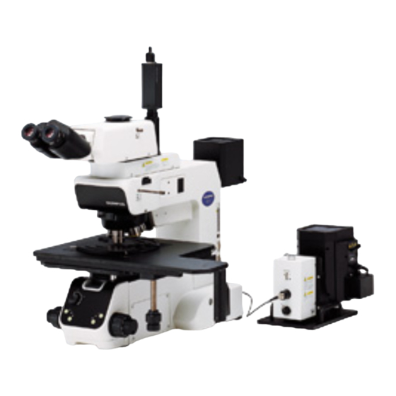
NOMENCLATURE The modules enclosed in belong to the U-UVF248 UV Microscope Unit. Other modules should be prepared by the user. }If you have not completed the assembly yet, see chapter 7, “ASSEMBLY” before proceeding to the following. TV camera/monitor for UV observation... -
Page 9: Controls
U-UVF248 CONTROLS UV248 Observation Tube U-UVF248IM UV light guide mount (Page 15) C-mount for TV camera for UV observation (Page 13) Illumination lens adjustment screw* Visible light observation tube mount With built-in UV cut filter TV adapter clamping screw (Page 13) - Page 10 Lamp Housing for Mercury/ Xenon Burner U-LH80HGXE Burner socket (Page 14) Collector lens focusing knob (Page 8) Burner centering knobs (Page 8) UV Light Guide U-UVF2FB/U-UVF5FB Input connector (Page 15) Output connector (Page 15) Power Supply for Mercury/ Xenon Burner (Mfd.
-
Page 11: Preparation
U-UVF248 PREPARATION Centering the Mercury/Xenon Burner (Figs. 1 & 2) ² ³ 1. To prevent the UV rays from being output unexpectedly, set the shutter selector lever @ of the light source box to the bottom position (marked {). 2. Turn on the power supply (by setting the power switch to “ ” and then setting the start switch to ON) to ignite the burner, and wait for 5 to 10 minutes until the arc image stabilizes. -
Page 12: Adjusting The Illumination Center
Adjusting the Illumination Center (Figs. 3 & 4) }This adjustment consists of aligning the UV light guide with the center of the MApo100X objective for 248 nm UV observation. 1. Set the light path selector lever @ of the reflected light illuminator to the BF position. -
Page 13: Summary Of Visible/Uv Light Observation Procedure
U-UVF248 SUMMARY OF VISIBLE/UV LIGHT OBSERVATION PROCEDURE }Before turning on the system, be sure to close the shutter by setting the shutter selector lever of the UV248 light source box to the bottom position (marked {). (Operation) 1. Switch on the power supply for mercury/xenon burner (by setting the Turn on the system. -
Page 14: Specifications
SPECIFICATIONS UV248 Observation Tube U-UVF248IM Specifications Item Visible light path UV light path Tube magnification 1X (with built-in UV cut filter) 2.5X Field number FN 22 (FN 20 for camera observation) FN 12.5 (Actual field: 50 μm) Optical wavelength Visible light 248 ±4 nm Applicable objectives UIS2 (UIS) series... -
Page 15: Troubleshooting Guide For Uv Observation
U-UVF248 TROUBLESHOOTING GUIDE FOR UV OBSERVATION If problems occur, please review the following list and take remedial action as needed. If you cannot solve the problem after checking the entire list, please contact Olympus for assistance. Page Trouble Cause Remedy... -
Page 16: Assembly
ASSEMBLY # Some of the modules already mounted on the microscope system should be dismounted when mounting this unit. When dismounting or mounting a module, handle it carefully, remove dirt or dust on the mounting section and take care not to damage the module. Attaching the Reflected Light Illuminator Mount an applicable reflected light illuminator on the microscope frame. - Page 17 U-UVF248 Attaching the UV248 Light Source Box (Figs. 6 to 8) ² Attaching the Mercury/Xenon Burner (Figs. 6 & 7) The burner and areas near it will be extremely hot during and right after use. To prevent burns, wait until the burner and lamp housing have cooled down after turning the burner off.
- Page 18 Attaching the Lamp Housing (Fig. 8) ² 1. Loosen the two lamp housing clamping screws @ of the UV248 light source box. 2. Insert the mount seat ² of the lamp housing into the mount and tighten the clamping screws @. Attach the lamp housing and take care not to tilt it.
- Page 19 U-UVF248 Connecting the Power Supply for Mercury/ (Fig. 11) Xenon Burner }For the basic connections, refer to the instruction manual provided with ² the power supply for mercury/xenon burner. The following description pertains to the settings required for use of this unit and the method of attaching the conversion cable.
-
Page 20: Lamp Housing Inspection Sheet
{If there is any ( ) mark noted, immediately stop use of the product, and contact Olympus for detailed inspections or replace the lamp housing. {If you detect an abnormality other than that listed below or with other Olympus product, also stop the use of the product and contact Olympus for detailed inspections. - Page 21 MEMO...
- Page 22 MEMO...
- Page 24 Manufactured by Distributed by AX7645 03...
Need help?
Do you have a question about the U-UVF248 and is the answer not in the manual?
Questions and answers