Table of Contents
Advertisement
Quick Links
Advertisement
Table of Contents

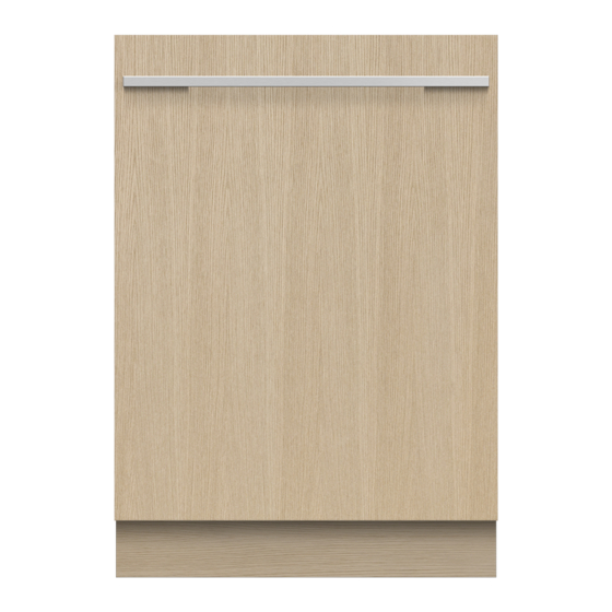
Summary of Contents for Fisher & Paykel DW60U6I
- Page 1 DISHWASHER DW60U6I & DW60U2I models INSTALLATION GUIDE NZ AU...
-
Page 2: Safety And Warnings
SAFETY AND WARNINGS IMPORTANT SAFETY INSTRUCTIONS WARNING! Ensure all water connections are turned OFF. It is the responsibility of the plumber and Electrical shock hazard electrician to ensure that each installation complies with all Codes and Regulations. Before installing the dishwasher, remove the house fuse or open the circuit The dishwasher MUST be installed to allow for future removal from the enclosure if breaker. -
Page 3: Prior To Installation
PARTS SUPPLIED TECHNICAL DATA Technical data Check the electrical data on the rating label (located on the left-hand side of the dishwasher’s stainless steel inner door). Should the data on the rating label be different to those specified below, consider those on the rating label as correct. DW60U2I1 models DW60U6I1 models Capacity... -
Page 4: Product Dimensions
PRODUCT DIMENSIONS NOT TO SCALE PLAN PROFILE DD60DU PRODUCT DIMENSIONS Overall height of product* 820 - 880 Overall width of product (excl. side seals) Overall depth of product (excl. custom panel & handle) Depth of toekick 30 - 90 Height from floor to bottom of custom panel 100 - 212 Depth of open door (measured from front of chassis) (excl. -
Page 5: Cabinetry Dimensions
CABINETRY DIMENSIONS PLAN PROFILE DD60DU CABINETRY DIMENSIONS Inside width of cavity 600 - 610 Inside height of cavity* 820 - 880 Minimum clearances from adjacent cabinetry Inside depth of cavity min. 574 * depending on adjustment of levelling feet min. 13 mm min. -
Page 6: Cavity Preparation
CAVITY PREPARATION IMPORTANT! To prevent possible steam damage to the cabinetry, ensure that any bare wood surrounding the dishwasher is sealed with an oil-based paint or moisture-proof polyurethane. IMPORTANT! Apply moisture protection tape The power outlet must be Apply moisture protection tape to located in a cabinet adjacent the underside of the benchtop. - Page 7 CUSTOM DOOR PANEL PREPARATION FRONT PANEL MATERIAL SPECIFICATIONS 2MM PILOT HOLE LOCATIONS FOR FIXINGS The front of the dishwasher can be fitted with a front panel with the following If the overhang of your panel is between 34mm and 54mm use the below guide to specifications: mark out the locations for your fixings.
- Page 8 ATTACHING CUSTOM DOOR PANEL Close the door of the Insert Ø3.9 x 13mm screws dishwasher, then hang through pilot holes and Adjust the placement of the the custom panel onto attach the small slider door to the correct position. the front of the door. bracket to panel.
- Page 9 Cut back excess. IMPORTANT! DW60U6I models only: Toe kick can protrude no more than 90mm out from the dishwasher to ensure that the visibility of the floor light is not obstructed.
- Page 10 SECURING PRODUCT Centre product As you push product in, pull through hoses and cord, ensuring they don’t get kinked or twisted. Plastic spacers can be cut to size then taped to the sides of the cut path dishwasher to improve example overall stability.
- Page 11 PLUMBING AND DRAINAGE OPTIONS. DETERMINE WHICH IS MORE SUITABLE. Dishwasher and Ø 38 mm Standpipe Dishwasher using drain hose joiner onto sink trap/waste tee Installer to provide drain hose joiner to suit If space is limited If space is limited min.
- Page 12 CONNECT INLET HOSE TO COLD WATER PLUG PRODUCT IN min. 10mm 3/4” BSP connector No leaks! Ensure the supplied rubber washer is fitted inside the coupling. Tighten coupling with spanner. Electrical connection Plumbing -- Water inlet connection IMPORTANT! The dishwasher must not be connected to the electrical supply while installation The appliance should be connected to the water main using the new water inlet hose supplied.
-
Page 13: Troubleshooting
TROUBLESHOOTING Excessive water remaining above the filter plate, after the rinse cycle (This can be displayed as an fault) Check for a kinked drain hose, blocked waste connection, highloop not properly installed, drain hose not routed correctly or spray arms not in place. No water supply (This is displayed as an fault) Check water is connected and turned on. -
Page 14: Final Checklist
FINAL CHECKLIST TO BE COMPLETED BY THE INSTALLER Check that the door opens and closes freely without resistance to adjacent Check all parts are installed. cabinetry. Ensure that all panels and parts thereof are secure and final electrical tests have been Check that the electrical outlet is accessible and located in an adjacent cupboard. - Page 16 FISHERPAYKEL.COM © Fisher & Paykel Appliances 2018 All rights reserved. The product specifications in this booklet apply to the specific products and models described at the date of issue. Under our policy of continuous product improvement, these specifications may change at any time. You should therefore check with your Dealer to ensure this booklet correctly describes the product currently available.


Need help?
Do you have a question about the DW60U6I and is the answer not in the manual?
Questions and answers