Table of Contents
Advertisement
Quick Links
Advertisement
Table of Contents

Related Manuals for CHAINTECH V915P


Summary of Contents for CHAINTECH V915P
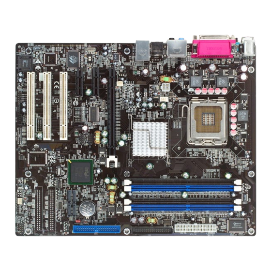
- Page 1 CHAINTECH V915P Intel 915P & ICH6 ATX Motherboard Reference Manual...
- Page 2 According to 47 CFR, Parts 2 and 15 of the FCC Rules The following designated product: EQUIPMENT: MAINBOARD MODEL NO.: V915P is a Class B digital device that complies with 47 CFR Parts 2 and 15 of the FCC Rules. Operation is subject to the following two conditions: 1.
- Page 3 Federal Communications Commission Statement This device complies with FCC Rules Part 15. Operation is subject to the following two conditions: * This device may not cause harmful interference. * This device must accept any interference received, including interference that may cause undesired operation. This equipment has been tested and found to comply with the limits for a Class B digital device, pursuant to Part 15 of the FCC Rules.
-
Page 4: Table Of Contents
SPECIFICATIONS ....................1 INTRODUCTION....................4 .......................4 HARDWARE SETUP ....................9 ..................10 NSTALLING OOLING .................... 11 NSTALLING EMORY ..................12 TORAGE ONFIGURATION ................13 RONT ANEL ONFIGURATION ................14 ANEL ONFIGURATION .....................17 UDIO ONNECTORS ........................18 LOTS ................19 OWER UPPLY TTACHMENTS BIOS SETTINGS ....................20 ....................20 EROS AND ONES ........................20 ......................22 DVANCED... - Page 5 ........................71 HW M ONITOR ......................76 EFAULTS ......................77 ........................78 BIOS SETTINGS ....................79 ..................79 EROS ET DES UNS ....................79 RINCIPAL ........................81 VANCE ) ................91 ERIPHERALS ERIPHERIQUES ........................97 OWER HW M ....................101 ONITOR ......................102 EFAULTS ........................103 SOFTWARE ......................104 NOTE........................106 HOW TO CONTACT CHAINTECH..............107...
-
Page 7: Specifications
Specifications CPU: ® Supports Socket 775 Pentium 4 Prescott processor Supports Hyper-Threading Technology 533/ 800 MHz FSB (Front Side Bus) frequencies Chipset: Northbridge Chipset – Intel® 915P Southbridge Chipset – Intel® ICH6 I/O Controller – Winbond W83627THF HD Aduio Codec – Realtek ALC880 Gb LAN Controller –... - Page 8 Universal Serial Bus: Supports up to 8 USB ports for USB compliant interface devices Supports USB 2.0 Enhanced Host Controller Interface (EHCI) and USB 1.1 Universal Host Controller Interface (UHCI) Onboard IDE Controller: Supports Ultra ATA 66/ 100, DMA and PIO modes Supports IDE interface with CD-ROM Supports high capacity hard disk drives IDE slot can support 2 IDE drives...
- Page 9 1. Standard & Bi-direction Parallel Port 2. Enhanced Parallel Port (EPP) 3. Extended Capabilities Port (ECP) Contains one serial port, 16550 UART Supports PS/2 mice and PS/2 keyboards Supports 360 KB/720 KB/1.2 MB/1.44 MB/2.88 MB floppy disk drives BIOS: Phoenix-Award™ BIOS Supports APM1.2 Supports ACPI2.0 power management...
-
Page 10: Introduction
Thank you for choosing Chaintech V915P motherboard. Before building your own perfect PC and installing and configuring its components, you need to have a clear idea of what you truly get by buying the Chaintech V915P mobo to pick the best components and enhance the performance for your flesh and blood. - Page 11 Intel 915P This Northbridge is also known as the Memory Controller Hub. This part of the chipset provides the system bus interface, memory controller, PCI-Express interface and hub interface for I/O. Intel ICH6 This Southbridge is also known as the Input/Output Controller Hub, and controls the system's access to the outside world, such as the PCI bus, USB ports, IDE sockets, Serial ATA ports and so on.
- Page 12 PCI-Express X16 Your PCI-E x16-based graphics card goes here. PCI-Express X1 Your PCI-Express x1-based expansion cards go here. PCI Slots Your expansion cards go here, but bear in mind that more is not necessarily better. FDC (Floppy Disk Connector) As its name suggests, this connector connects to your floppy disk drive via the FDC cable.
- Page 13 BIOS The Basic Input/Out System (BIOS) contains the code to burn up your PC, test it and start loading an Operating System. Battery The BIOS set-up data is held in CMOS RAM, thanks to the power taken from this battery. Rear I/O panel Most of the I/O ports will be found here, but not all.
- Page 14 USB Connectors 3/4 This motherboard has two extra ports that you won't find on the rear I/O panel. To access them, you will need to run a cable from a socket on the motherboard to a slot connector, which screws into a vacant PCI backplate. Alternatively, connect to the front of your PC if your case has front-mounted ports.
-
Page 15: Hardware Setup
ESD mats, or other protective measures to avoid damaging the processor and other electrical components in the system. Warning Do not touch socket sensitive contacts. Chaintech assumes no responsibility for the potential damages caused by this action and therefore the warranty we provide may be invalid. -
Page 16: Installing Cooling Fan
#6 Close the socket by 1. Close the Load Plate 2. While pressing down lightly on Load Plate, engage the Load Lever. 3. Secure Load Lever with Load Plate tab under retention tab of Load Lever Installing Cooling Fan .Warning For a safety landing, avoid leaving prongs on hard surface. -
Page 17: Installing Memory
Installing Memory Take great care when handling and implementing the memory, because it is not cheap anymore. Memory DIMMs will only go in one way, so don't try and force it. Line up the DIMM and push down gently. Then, when it's in place, lock it in with white connectors, as shown on the right image. -
Page 18: Storage Configuration
Storage Configuration So far so good, now it is time to install the storage devices for your mainboard. Floppy Disk Connector: FDC This mainboard provides a standard floppy disk connector (FDC) that supports 360K, 720K, 1.2M, 1.44M and 2.88M floppy diskette drives. This connector supports the floppy drive ribbon cables provided in the packaging. -
Page 19: Front Panel Configuration
Front Panel Configuration SW/LED HD LED (Hard Drive LED Connector) This connector can be attached to an LED on the front panel of a computer case. The LED will flicker during any disk activity. RST SW (Reset Connector) This connector can be attached to a momentary SPST switch. This switch is normally left open. -
Page 20: Rear Panel Configuration
SPEAKER (Speaker) A front panel speaker can be attached to this connector. This speaker is used for audible beeps during the boot up process (Power On Self-Test). A single “short beep” is normal, while “irregular beeps” signal problems. Rear Panel Configuration PS/2 Mouse &... - Page 21 Parallel Interface Port: PRT The parallel port on your system has a 25-pin, DB25 connector that is used to interface with parallel printers and other devices using a parallel interface. The Serial Interface: COM1 The serial interface port is sometimes referred to as an RS-232 port or an asynchronous communication port.
- Page 22 USB & (Gb) LAN Connectors: USB/ Gb LAN This mainboard comes with 4 USB ports and a Gb/s LAN port. The USB connectors are used to attach to keyboards, mice and other USB devices. You can plug the USB devices directly into this connector. The LAN connectors can be attached directly to a network.
-
Page 23: Audio Connectors
Front USB Headers: USB3/ USB4 This mainboard provides 2 USB headers on the board allowing for 4 additional USB ports. To make use of these headers, you must attach a USB bracket/cable with USB ports (some models will come packaged with a USB 4-port bracket-cable). -
Page 24: Slots
and speakers. An SPDIF/Audio bracket is optionally packaged with some models. S/PDIF Header: SPDIF S/PDIF (Sony/Philips Digital Interface) is an audio transfer file format which provides high quality audio using optical fiber and digital signals. This mainboard is equipped with an SPDIF header and must be used with a bracket-cable containing S/PDIF ports. -
Page 25: Power Supply Attachments
PCI Slots: PCI1/ PCI2/ PCI3 This mainboard is equipped with 3 standard PCI slots. PCI stands for Peripheral Component Interconnect and is a bus standard for expansion cards, which has, for the most part, supplanted the older ISA bus standard. This PCI slot is designated as 32 bit. -
Page 26: Bios Settings
BIOS Settings Zeros and ones Phoenix-Award BIOS has a built-in setup program that allows users to modify the basic system configuration. This information is stored in CMOS RAM whose power is supplied by a battery so that it can retain the setup information even when the power is turned off. - Page 27 IDE Channel 0 Master/Slave You can press Enter to see the submenus they contain. Drive A Allows you to select the type of floppy drive installed for drive A. Available options are None, 365K, 5.25in, 1.2M, 5.25in, 702K, 3.5in, 1.44M, 3.5in and 2.88M, 3.5in. Video Allows you to select the type of displaying standard you are using.
-
Page 28: Advanced
Advanced Removable Device Priority Select removable device priority, such as Floppy Disks, LS120, ZIP-100, USB-FDD and USB-ZIP. Hard Disk Boot Priority Select hard disk boot priority. First/Second/Third Boot Device Allow you to select the First, Second and Third Boot Device. If your computer is newly constructed, the next thing you want to do is load the Operating System from scratch, directly off its CD. - Page 29 an error message. However, the system will be allowed to continue the boot process. If this feature is disabled, your computer will skip the floppy drive check, which speeds up the booting process by several seconds. Since the floppy check is really pointless, it is recommended that you disable this feature for a faster booting process.
- Page 30 CPU L1 & L2 Cache Cache memory is much faster than conventional DRAM system memory. These fields allow you to enable or disable the CPUs Level 1 built-in cache and Level 2 external cache. Both settings are left as Enabled to significantly enhance the performance of your computer.
- Page 31 Windows NT environment. Choose the new 1.4 version for Windows 2000 and Windows XP. Options: 1.4 (default)、1.1 OS Select For DRAM > 64MB IBM’ s relic. If your system's DRAM is larger than 64MB and you are running OS/2, select OS/2 as the item value. Otherwise, set the item value to Non-OS/2 for all other operating systems.
- Page 32 giving you an edge in overclocking your system. So, if you hit a snag while overclocking, try increasing the CAS latency time. DRAM RAS# to CAS# Delay This item allows you to select a delay time between the CAS and RAS strobe signals.
- Page 33 Memory Hole at 15M-16M Enabling this function will reserve the memory address space between 15MB and 16MB for ISA expansion cards. However, it will also result in not allowing the system to have access to memory above 16MB. Please note that some expansion cards require this setting to be enabled. The default setting is Disabled.
- Page 34 resolve the conflict and allow the operating system to load normally. Please note that the BIOS will automatically reset it to the default setting of Disabled after reconfiguring the new ESCD. So, there is no need for you to manually disable this feature after rebooting. Resources Controlled By This BIOS feature determines if the BIOS should automatically configure IRQ and DMA resources.
- Page 35 active PCI device has to complete its transactions within 32 clock cycles or hand it over to the next PCI device. For better PCI performance, a longer latency should be used. Try increasing it to 64 cycles or even 128 cycles.
- Page 36 Some BIOS's have a Smart Clock setting which can turn off AGP, PCI & SDRAM clock signals when not in use which reduces EMI without giving system stability problems. This also gives a slight reduction in power consumption. PCI Speed Setting This feature allows you to set the PCI frequency.
-
Page 37: Peripherals
Default CPU Voltage (Volt) This item displays the CPU default Voltage. CPU Voltage (Volt) This item allows you to adjust your CPU core voltage. Options: 0.85~1.9. The default depends on your CPU. Peripherals Init Display First Set to PCIEx if your primary display is your PCI-E adapter or to PCI if the primary display is a PCI video card. - Page 38 IDE channel0/channel1 Master/Slave PIO Set all of these to Auto and let the BIOS determine if each drive is capable of Ultra DMA support, and its respective PIO mode. IDE channel0/channel1 Master/Slave UDMA Same as above. OnChip Serial ATA Setting On-Chip Serial ATA This field allows you to select the on-chip Serial ATA operating mode which will determine how you will use your Serial ATA drives with the...
- Page 39 When you install the SATA device(s) to the SATA1 or 3 or 1+3, this item should be set to channel 1. When you install the device(s) to the SATA2 or 4 or 2+4, this item should be set to channel 0. Options: Channel 0 (default)、channel 1 SATA Port This item will display which IDE channel will be used to the SATA...
- Page 40 Onboard I/O Chip Setup Power On Function This option allows you to select a way to power on your computer. Options: Password、Hot KEY、Mouse Left、Mouse Right、Any KEY、 BUTTON ONLY (default), and Keyboard 98 KB Power On Password This it the password that your system will use as part of the power-on sequence.
- Page 41 IR Transmission Delay This item allows you to enable/disable IR transmission delay. This field is only configurable if “UART Mode Select” is set to “ASKIR” or “IrDA”. Options: Enabled (default)、Disabled UR2 Duplex Mode Select the transmission mode used by the IR interface. Full-duplex mode permits simultaneous bi-directional transmission.
- Page 42 ECP Mode Use DMA Select a DMA Channel for the parallel port when using the ECP mode. This field is only configurable if “Parallel Port Mode” is set to “ECP”. Options: 3 (default)、1 PWRON After PWR-Fail This field will determine whether your system will boot after restoring power after a power failure.
-
Page 43: Power
Power ACPI Suspend Mode This item specifies the power saving modes for ACPI function. Available options are: 1. S1 (POS) The S1 state is low power state. In this state, no system context (CPU or Chipset) is lost and the hardware maintains all system contexts. 2. - Page 44 Power Management The level of power management can be set. Disable if you don't want any of it. You can use min or max settings that are pre-determined, or set to "User Define" to specify. Video Off Method Blank Screen: The system BIOS will only blank off the screen when disabling video.
- Page 45 Options: Disabled(default)、1Min、2Min、4Min、8Min、12Min、20Min、 30Min、40Min、1Hour HDD Power Down It shuts down any IDE hard disk drives in the system after an idle period. This feature does not affect SCSI hard drives. Disabled is recommended. Soft-Off by PWRBTN When set to Delay 4 Sec., this function allows the power button to put the system in Suspend, a power saving mode.
- Page 46 field is only configurable when “RTC Wake Up” is set to “Enabled”. Time (hh:mm:ss) Alarm You can choose the hour, minute and second the system will boot up. This field is only configurable when “RTC Wake Up” is set to “Enabled”. Reload Global Timer Events When a system goes into suspend mode, certain devices must be inactive for a period of time.
-
Page 47: Hw Monitor
HW Monitor Case Open Warning If this function is set to “Enabled” and the case had been previously opened, the system will automatically display alert messages on the screen when you power on your computer. If this function is set to “Disabled”, the system will not show alert messages when you power on your computer even if the case had been previously opened. -
Page 48: Defaults
Defaults Load System Default Settings To avoid errors, this option allows you to recover the original defaults of BIOS. In fact, this is the first skill you should know as you try to set other defaults of BIOS. Load System Turbo Settings This option has the similar function to the previous one. -
Page 49: Exit
Exit Save & Exit Setup If you select this and type Y followed by Enter, the values entered in the setup utilities will be recorded in the CMOS memory of the BIOS chip. Exit Without Saving Same as above, but without saving. -
Page 50: 主機板 Bios 系統設定
主機板 BIOS 系統設定 簡介 本 章 節 為 您 介 紹 建 立 在 主 機 板 Flash ROM BIOS 系 統 裡 的 PHOENIX-AWARD™ 設定程式。此程式可讓使用者能夠修改主機板 的系統基本設定值,並將其儲存在主機板的快閃記憶體晶片㆖,即使 系統關機,BIOS 的設定資料亦不會消失。 在您電腦系統 Flash ROM (Read Only Memory) 裡面的 PHOENIX- AWARD™ BIOS 設定程式是㆒種標準版本的 BIOS 設定程式。可支 ®... -
Page 51: 主選單(Main Menu)
主選單(Main Menu) 進入 PHOENIX-AWARD™ BIOS CMOS 設定功能時,首先呈現在您 眼前的就是主選單。主選單使您可以選擇您想要更改設定的功能選 項。利用㆖、㆘、左、右的箭頭鍵選擇您所要修改的項目,並按㆘ <Enter> 鍵以進入此選項的子選單。 進階功能設定(Advanced) 在此選單㆗您可設定開機磁碟的優先順序,另外還有幾個子選單包括 有 BIOS 進階功能設定、晶片組的進階功能設定、PnP/PCI 組態設定 及頻率/電壓的設定,讓您可以設定 BIOS 所提供的特殊進階功能。 整合週邊系統設定(Integrated Peripherals) 在此選單㆗您可設定所有週邊設備的相關設值,如:模式設定、致能 設定、位址設定等。... -
Page 52: 電源管理設定(Power Management)
電源管理設定(Power Management) 當您用自己㆒貫的方式來使用電腦時,電源管理模式設定可讓您的系 統達到最省電的模式。 電腦硬體監控功能(Hardware Monitoring) 在 BIOS 設定㆗提供了系統硬體監控的功能,包括了機殼打開警示功 能、系統自動偵測溫度/電壓/風扇轉速功能。 載入預設值(Load Defaults) 您可在此選單㆗載入 BIOS 設定的安全預設值,使電腦獲得穩定的運 作效能。 退出選單(Exit Menu) 在此選單㆗您可選擇儲存所有 CMOS 設定並離開(Save & Exit Setup) 或是選擇離開但不儲存任何設定之更改(Exit Without Saving)。 當您進入 BIOS 設定畫面㆗時,請依照㆘列步驟載入基本 BIOS 的 CMOS 設定。 載入預設值 進入載入預設值(Default)選單㆗,選擇【Load System Default Settings】... - Page 53 並按㆘ Enter 鍵後,請按【Y】及【Enter】鍵,即可載入基本 BIOS 的 CMOS 設定。 儲存 CMOS 設定並離開 進入退出選單(Exit)㆗,選擇【Save & Exit Setup】並按㆘ Enter 鍵後, 請按【Y】及【Enter】鍵,即可儲存 CMOS 設定並離開 BIOS 設定畫 面。...
-
Page 54: Bios 설정
BIOS 설정 는 설정 프로그램을 내장하여 사용자가 기본 시스템 Phoenix-Award BIOS 환경을 설정, 수정할 수 있도록 합니다. 독립 배터리로 전기가 공급되어 시스템이 꺼져 있을 때도 설정값이 유지됩니다. 사용자가 시스템의 전원을 켜거나 재시작할 때 [Delete] 키를 눌러 BIOS 의 설정 프로그램으로 들어갈 수 있습니다. BIOS 를 최적화하기 전에 모든 기능이... - Page 55 날짜 (mm/date/year) 및 시간 (hh/mm/ss) 시스템의 날짜와 시간을 설정할 수 있습니다. IDE Channel 0 Master/Slave 서브메뉴를 보기위해서 엔터키를 누릅니다. Drive A 플로피 장치 모델을 선택합니다. 가능한 옵션은 None, 365K, 5.25in, 1.2M, 입니다. 5.25in, 702K, 3.5in, 1.44M, 3.5in, 2.88M, 3.5in Video 시스템에...
- Page 56 Security 바이오스 설정으로 들어갈 경우 비밀번호를 설정할 수 있습니다. 이 기능을 설정하면 바이오스 설정을 하기 위하여 비밀번호를 물어보게 됩니다. Base Memory 부팅 중 감지되는 기본 메모리의 용량을 나타냅니다. Extended Memory 부팅 중 감지되는 확장 메모리의 용량을 나타냅니다. Total Memory 시스템의 총 메모리 용량을 나타냅니다.
-
Page 57: Advanced
Advanced Removable Device Priority 이동 가능한 장치의 우선순위를 정합니다. 예를 들어 Floppy Disks, LS120, ZIP-100, USB-FDD, USB-ZIP 등이 있습니다. Hard Disk Boot Priority 하드디스크의 부팅 우선순위를 정합니다. First/Second/Third Boot Device 첫번째, 두번째, 세번째 부팅 장치를 선택할 수 있습니다. 만약 CD-ROM 에서 부팅하기를 원할 경우 이곳에서 부팅 우선순위를 정할 수 있습니다. - Page 58 Boot up Floppy Seek 이 옵션이 활성화되어 있을 경우 컴퓨터는 부팅시 플로피 디스크를 검색하여 검색이 안되면 에러메시지를 보여줍니다. 그 후 정상적인 부팅이 이루어 집니다. 비활성화 되면 플로피디스크 검색을 건너뛰게 되므로 부팅 속도를 향상시킬 수 있습니다. 이 부분은 비활성화 [disable]로 하시길 권장합니다.
- Page 59 Limit CPUID MaxVal 가 3 으로 설정되어 있을 경우 이 항목은 Limit CPUID MaxVal WinodwsXP 에서 반드시 로 설정되어야 합니다. 가능한 옵션은 “Disabled” Enable, Disable (기본값) 입니다. Virus Warning 이 옵션을 활성화 하면, 프로그램이 디스크 드라이브의 부트부분에 쓰기를 시도했을 때 경고메시지와 비프음을 나타냅니다. CPU L1 &...
- Page 60 방지하기 위해서 입니다. Boot Up NumLock Status 키보드 숫자패드를 숫자키로 사용하거나 화살표키로 사용하도록 설정할 수 있습니다. 이 옵션을 On 하면 숫자키로 사용할 수 있고, Off 하면 화살표키로 사용 가능합니다. Typematic Rate Setting 이 기능이 활성화되면 사용자는 다음의 두가지에 대해서 설정이 가능합니다.
- Page 61 OS Select For DRAM > 64MB 시스템의 DRAM 이 64M 보다 크고 사용자가 OS/2 를 실행한다면 OS/2 를 설정합니다. 또한 다른 OS 를 위한 Non-OS/2 로 설정합니다. HDD S.M.A.R.T Capability 이 항목은 하드디스크 장치의 예상 가능한 에러를 자체적으로 진단하여 부팅 스크린에 나타내는 기능을 합니다. Intel OSB Logo Show 이...
- Page 62 레이턴시를 다루지 못할 수 도 있으며, 시스템이 불안정해 질 수 도 있습니다. # to CAS# Delay DRAM RAS 이 항목은 CAS 와 RAS 신호간에 지연시간을 설정할 수 있도록 합니다. 이 항목은 DRAM 이 쓰기 (Written to), 읽기 (Read from) 또는 리플레시 (Refreshed) 로...
- Page 63 입니다. System BIOS Cacheable 이 항목을 활성화 하면 시스템 바이오스 롬의 더 낳은 퍼포먼스의 결과를 가져오는 F000h-FFFFFh 부분의 케싱을 가능하게 합니다. 그러나 만약 이 부분에 다른 프로그램이 쓰기를 시도하게 되면, 에러를 발생시킬 수도 있습니다. 이 부분을 기본 설정값으로 남겨두시기를 권장합니다. Video BIOS Cacheable “Enabled”를...
- Page 64 PCI Express Root Port Func PCI Express Port1/2 이 항목은 여러분이 PCI Express x 1 포트 1/2 항목을 활성화 혹은 비활성화 하게 합니다. 가능한 옵션으로는 Auto(기본값), Disabled 가 있습니다. PCI-E Compliancy Mode 이 항목은 여러분이 PCI-E 승락(Compliancy) 모드를 설정 가능하게 합니다. 가능한...
- Page 65 구성을 ESCD 에 기록하게 됩니다. 한번 활성화한 이후에는 자동적으로 비활성화로 바뀌게 되니 이 항목으로 다시 들어와서 비활성화로 바꾸실 필요는 없습니다. Resources Controlled By 이 항목은 바이오스가 자동적으로 IRQ 와 DMA 같은 것을 설정할 수 있는 지를 설정합니다. 대체적으로 바이오스는 여러분의 컴퓨터의 장치의 IRQ 와...
- Page 66 PCI / VGA Palette Snoop 이 옵션은 여러분이 MPEG 카드 또는 그래픽 카드 기능 연결단자의 에드온 카드를 사용할 때만 유용하게 사용할 수 있습니다. 이것은 잘못된 색상을 “Snooping”을 통하여 재생산되어 정확한 색상을 나타내게 됩니다. 이 기능은 또한 MPEG 카드를 쓴 후 스크린이 까맣게 변하는 문제도 해결하여...
- Page 67 PCI Express relative items Maximum Payload Size 이 항목은 PCI 익스프레스의 시간당 최대 하중의 크기를 설정할 수 있습니다. 가능한 옵션은 4096(기본값), 128, 256, 512, 1024, 2048 입니다. Frequency/Voltage Control Spread Spectrum 이 기능은 EMI 를 감소시켜줍니다. 그러나 이 항목을 활성화 함으로써 SCSI 장비...
- Page 68 CPU Speed Setting 이 항목은 여러분이 설정한 CPU 속도를 보여줍니다. 만약 여러분이 “CPU Host Frequency” 또는 “CPU Clock Ratio”를 바꾸지 않았다면 이 항목은 현재 CPU 속도를 나타낼 것 입니다. CPU Host Frequency (MHz) 이 항목은 CPU 의 호스트 주파수를 나타냅니다. 여러분은 XXX 부터 333 까지...
-
Page 69: Peripherals
CPU Voltage (Volt) 이 항목은 CPU 코어 전압을 조절할 수 있게 합니다. 가능한 옵션은 0.85~1.9 입니다. 기본값은 여러분의 CPU 기본값으로 고정됩니다. Peripherals Init Display First 여러분의 주 디스플레이 장치가 PCI 익스프레스 일 때, PCI 디스플레이 장비를 설정합니다. OnChip IDE Device IDE HDD Block Mode 최대의... - Page 70 가지고 있습니다. 이 두개의 IDE 채널은 IDE1, SATA1/2/3/4 커넥터 사용을 위한 것입니다. Enabled 를 선택하면 첫번째 혹은 두번째 IDE 인터페이스가 지원됩니다. 만일 여러분이 프라이머리/세컨더리 인터페이스를 설치하려고 한다면 Disabled 를 선택하십시오. 가능한 옵션은 Enabled(기본값), Disabled 입니다. IDE channel0/channel1 Master/Slave PIO 만일 모든 장치가 울트라 DMA 와 각각의 PIO 모드를 지원이 가능하면 이 설정을...
- Page 71 기본값 바이오스는 자동적으로 현재의 시리얼 ATA 장비를 감지할 Auto( 것입니다. 또는 드라이버 또는 드라이버 à 증대모드 1) IDE + 4 ( 3) SATA 또는 드라이버 또는 드라이버 반드시 SATA1+3 1) IDE + 2 ( 1) SATA 혹은 SATA2+4 와 함께 연결되어야 합니다. à 조합 모드 또는...
- Page 72 PATA IDE Mode 이 항목은 PATA IDE 장비를 위한 IDE 채널을 선택할 수 있게 합니다. SATA 장치를 SATA1 또는 3 또는 1 + 3 으로 설치하면 이 항목은 반드시 채널 1 로 설정되어야 합니다. SATA 장치를 SATA2 또는 4 또는 2 + 4 로 설치하면...
- Page 73 USB Keyboard Support 활성화 될 경우 USB 용 키보드를 지원합니다. 사용 가능한 옵션은 Disabled(기본값), Enabled 입니다. Audio Device 이 항목은 온보드용 오디오 장치의 설정을 조절합니다. 사용 가능한 옵션은 있는 Auto(기본값), Disabled 입니다. Gigabit LAN Device 이 항목은 기가비트랜 장치를 활성화 또는 비활성화 시킬 수 있게 합니다. 사용...
- Page 74 Hot Key Power ON 이 항목은 “Power On Function” 이 “Hot Key”로 설정되어 있는 경우만 사용 가능합니다. 이 옵션은 핫 키와 컨트롤 키를 이용하여 컴퓨터의 전원을 켤 수 있습니다. 사용 가능한 옵션은 Ctrl-F1, Ctrl-F2, … … Ctrl-F12 입니다. Onboard FDC Controller 보드에...
- Page 75 IR Transmission Delay 이 항목은 IR 전송 지연을 설정합니다. “UART Mode Select”가 “ASKIR” 또는 “IrDA”로 설정되어 있을 때만 구성이 가능합니다. 사용 가능한 옵션은 Enabled(기본값), Disabled 입니다. UR2 Duplex Mode IR 인터페이스에 의해서 전송 모드를 선택합니다. “UART Mode Select”가 “ASKIR” 또는 “IrDA”로 설정되어 있을 때 풀 듀플렉스 모드는 동시 양방향 전송을...
- Page 76 Enhanced Parallel Port. Standard Printer Port. ECP+EPP ECP & EPP mode. 입니다. Normal EPP Mode Select EPP 포트의 종류를 1.7 또는 1.9 로 선택하십시오. 이 항목은 “Parallel Port Mode” 가 “EPP” 또는 “ECP+EPP 로 되어 있을 때만 설정이 가능합니다. 가능한 옵션은 EPP1.9(기본값), EPP1.7 입니다. ECP Mode Use DMA ECP 모드를...
-
Page 77: Power
Power ACPI Suspend Mode 이 항목은 ACPI 기능을 위한 절전에 관한 사항입니다. 가능한 옵션은 다음과 같습니다. 1. S1 (POS) S1 상태는 저 전력 상태입니다. 이 상태에서는 어떠한 시스템 구성요소 (CPU 나 각종 칩셋)에도 변화가 없으며 하드웨어의 모든 시스템 구성요소를 유지합니다. 2. - Page 78 선택됩니다. 그렇지 않으면 S1 이 선택됩니다. Run VGABIOS if S3 Resume S3 대기 기능으로부터 시스템에 재 동작할 때 VGABIOS 의 실행을 할 것인지를 설정할 수 있습니다. 이 기능은 “ACPI Suspend Type” 이 “S1(POS)”로 되어 있을 경우에는 구성할 수 없습니다. 가능한 옵션은 Auto(기본값), Yes, No 입니다.
- Page 79 있습니다. Video Off In Suspend 컴퓨터가 일시 정지 모드로 들어갈 때 모니터의 전원을 차단시킬지를 결정합니다. 가능한 옵션은 Yes, No(기본값)입니다. Suspend Type 이 항목은 ACPI 운영체제 시스템 하에서 일시정지 종류를 설정하도록 합니다. 가능한 옵션은 Stop Grant(기본값), PwrOn Suspend 입니다. Modem Use IRQ 이...
- Page 80 항목은 비활성화 (Disabled)로 해 놓으시길 권장합니다. Soft-Off by PWRBTN 이 항목을 로 설정했을 경우, 파워버튼을 누름으로써 시스템이 Delay 4 Sec 꺼지는 대신 대기모드로 들어갈 수 있도록 합니다. Instant-Off 로 설정을 했을 경우에 파워버튼을 누르게 되면 컴퓨터는 바로 종료되게 됩니다. Wake Up Control 항목을...
- Page 81 가능한 옵션은 Enabled 와 Disabled 가 있습니다. RTC Wake Up 이 항목이 활성화되면 RTC(Real-Time Clock) 알람의 시간과 날짜를 설정하여 시스템을 대기모드에서 재동작 하게 할 수 있습니다. 가능한 옵션은 Enabled, Disabled(기본값) 입니다. Date (of Month) Alarm 여러분은 특정한 날짜에 컴퓨터가 켜지도록 설정할 수 있습니다. 이 기능은...
-
Page 82: Hw Monitor
HW Monitor Case Open Warning 이 기능이 활성화 되어 있고, 케이스가 열려있게 되면, 시스템은 자동으로 컴퓨터의 전원이 들어올 때 스크린에 경고 메시지를 띄우게 됩니다. 가능한 옵션은 Disabled(기본값), Enabled 입니다. Smart CPUFAN Temperature 이 기능은 여러분이 CPU 의 온도를 설정할 수 있게 합니다. 만약 CPU 의 온도가... -
Page 83: Defaults
Defaults Load System Default Settings 이 항목은 바이오스의 조절이 잘못되었을 때 기본값으로 돌릴 수 있도록 합니다. 문제가 생겼을 경우 가장 먼저 해야 할 작업이 바이오스의 기본값을 불러오는 것입니다. Load System Turbo Settings 이 항목은 시스템의 성능을 더욱 효율적으로 해줍니다. 다만 시스템의 성능이... -
Page 84: Exit
Exit Save & Exit Setup 이 항목을 선택하고 “Y”를 치게 되면, 바이오스의 CMOS 메모리로 변경된 값들이 저장됩니다. Exit Without Saving 변경된 항목이 저장되지 않습니다. -
Page 85: Bios Settings
BIOS Settings Des Zéros et des uns La ROM du BIOS Phoenix Award possède un programme d’ installation intégré permettant aux utilisateurs de modifier la configuration de base du système. Cette information est stockée dans la RAM CMOS de sorte qu’ elle peut conserver les informations de paramétrage, même quand l’... - Page 86 IDE Channel 0 Maî tre/Esclave Vous pouvez appuyer sur Entrée pour voir les sous menus rattachés à cet élément. Lecteur A Cette option vous permet de choisir le type de lecteur de disquette installé pour le lecteur A. Les options disponibles sont Aucun (None), 365K, 5.25in, 1.2M, 5.25in, 702K, 3.5in, 1.44M, 3.5in et 2.88M, 3.5in.
-
Page 87: Avance
Mémoire Totale Montre la quantité de mémoire totale disponible dans le système. Avancé Removable device priority Choisissez la priorité des disques amovibles, comme un lecteur de disquette, LS120, ZIP-100, USB-FDD et USB-ZIP. Hard Disk Boot Priority Choisissez la priorité de démarrage des disques durs. First/Second/Third Boot Device Permet de choisir le Premier, Deuxième, et Troisième périphérique de démarrage. - Page 88 Boot up Floppy Seek Cette fonction du BIOS détermine si votre ordinateur doit vérifier la présence ou non, d'un lecteur de disquette durant le démarrage. Si activée (enabled), l'ordinateur recherchera et initialisera le lecteur de disquette. S'il ne peut pas en détecter, un message d'erreur apparaî tra. Toutefois le système sera autorisé...
- Page 89 Virus Warning Permet d'activer la fonctionVIRUS warning (alerte Virus) pour la protection des secteurs de boot des disques durs IDE. Si cette fonction est activée (enabled) et si quelque chose tente d'écrire des données dans cette zone. Le BIOS affichera un message d'alerte accompagné...
- Page 90 Typematic Delay (Msec) Le délai de répétition définit la durée, après avoir appuyé sur une touche, après laquelle un caractère commence à se répéter. APIC Mode En activant cette option, “MPS version control for OS” peut être paramétré. La position Désactivé (Disabled) est recommandée. MPS Version Control for OS La version 1.1 est la version la plus ancienne qui supporte plus de 8 IRQ dans un environnement Windows NT.
- Page 91 Advanced Chipset Features ( Fonctionnalités Avancées du Chipset DRAM Timing Selectable Cette fonction détermine la vitesse de la mémoire en utilisant les configuration SPD ou manuelle. Soyez certain que votre mémoire possède un SPD (Serial Presence Data), si vous choisissez l'option “By SPD”. Options: Manual、By SPD (default) CAS Latency Time CAS est un diminutif de «...
- Page 92 DRAM RAS# Precharge Cette fonction vous permet de choisir le temps de précharge DRAM RAS#. L'adresse ROW doit être préchargé avant la rafraî chissement de la DRAM Une mauvaise configuration peut entraî ner des données incomplètes. Ce champ est réglable seulement quand "DRAM Timing Selectable" est placée sur "manuel". Ce champ est verrouillé...
- Page 93 PCI Express Root Port Func PCI Express Port1/2 Cette fonction vous permet d'activer (enabled) ou non (disabled) les ports ½ PCI Express x 1. Options: Auto (default)、Disabled PCI-E Compliancy Mode Cet article vous permet de choisir le mode de compatibilité PCI-E. Options: V1.0a (default)、V1.0 PEG Force X1 Cette fonction vous permet de forcer le slot PCI-Express 16x à...
- Page 94 configurer automatiquement des ressources d'IRQ et de DMA pour les périphériques dans votre ordinateur. Par conséquent, il est recommandé que vous placiez cette option sur Auto. Cependant, si le BIOS a des problèmes pour assigner les ressources correctement, vous pouvez choisir l'option Manuelle (Manual) pour indiquer les champs IRQ et DMA.
- Page 95 après chaque changement pour déterminer le temps de Latence optimal pour votre système. Merci de noter qu'une Latence PCI plus longue n'est pas forcément meilleure. Une Latence trop longue peut aussi diminuer la performance, les périphériques PCI pouvant être bloqués trop longtemps. Ceci est particulièrement vrai avec une machine ayant beaucoup de périphérique PCI ou des périphériques PCI envoyant régulièrement des données au bus PCI.
- Page 96 fonctionnement ce qui réduit les IEM sans donner de problème de stabilité à votre système. Ceci permet également une légère réduction de la consommation d'énergie. PCI Speed Setting Cette fonction vous permet de définir la fréquence PCI. Auto est conseillé. PCI-E Speed Setting System Memory Frequency Idem.
-
Page 97: Peripherals (Peripheriques )
Default CPU Voltage (Volt) Cette fonction affiche le voltage par défaut du processeur. CPU Voltage (Volt) Cette fonction vous permet d'ajuster le voltage du core de votre processeur. Options: 0.85~1.9. Le statut par défaut dépend de votre processeur. Peripherals (Périphériques) Init Display First A définir sur PCI-Ex si votre périphérique d'affichage primaire est sur slot PCI-E ou sur PCI si votre périphérique d'affichage primaire est une carte... - Page 98 secondaire additionnelle. Options: Enabled (default) 、Disabled IDE channel0/channel1 Master/Slave PIO Définissez les tous sur Auto et laisser le BIOS déterminer si chaque lecteur est compatible Ultra DMA, ainsi que son mode PIO respectif. IDE channel0/channel1 Master/Slave UDMA Comme ci-dessus. OnChip Serial ATA Setting On-Chip Serial ATA Ce champs vous permet de choisir le mode opératoire Serial ATA intégré...
- Page 99 une restriction de Microsoft.) SATA Only: Choisissez cette option lorsque vous n'intsallez que des lecteurs SATA. PATA IDE Mode Cette fonction vous permet de choisir un canal IDE pour des périphériques PATA IDE. Lorsque que vous installez le(s) périphérique(s) SATA sur le SATA1 ou 3 ou 1+3, cette fonction doit être définie sur le canal 1.
- Page 100 Gigabit LAN Device Cette fonction activera (enable) ou désactivera (disable) le périphérique Gigabit LAN. Options : Enabled (défaut) 、Disabled IDE RAID Device Cette fonction vous permet d'activer (enable) ou de désactiver (disable) le périphérique IDE RAID. Options : Enabled (défaut) 、Disabled Onboard I/O Chip Setup Power On Function Cette option vous permet de choisir le mode d'allumage de votre ordinateur.
- Page 101 Onboard Serial Port 1 Choisissez une adresse correspondante à l’ interruption pour le premier et le second port série. Options : Disabled、3F8/IRQ4 (défaut pour le port1) 、2F8/IRQ3、 3E8/IRQ4、2E8/IRQ3、Auto UART Mode Select Cette fonction détermine le standard Infra Rouge (IR) utilisé. Options : Disabled (défaut) 、ASKIR、IrDA RxD, TxD Active Cette fonction détermine la fréquence RxD et TxD.
- Page 102 Onboard Parallel Port Choisissez une adresse et une interruption correspondante pour le port parallèle intégré. Options : 378/IRQ7 (défaut) 、278/IRQ5、3BC/IRQ7、Disabled Parallel Port Mode Cette option vous permet de choisir le mode du port parallèle intégré. Options : ECP (défaut) Extended Capabilities Port. Enhanced Parallel Port.
-
Page 103: Power
Power ACPI Suspend Mode Cet élément spécifie les modes d’ économie d’ énergie pour la fonction ACPI. Les options disponibles sont : 1. S1 (POS) L’ état S1 est l’ état de faible alimentation. Dans cet état, aucun contexte système (CPU ou Chipset) n’ est perdu et le matériel maintient tous les contextes système. - Page 104 Power Management Le niveau de gestion d'énergie peut être défini. Disable si vous n'en voulez aucune. Vous pouvez utiliser les paramètres min ou max qui sont prédéterminés, ou utiliser "User Define" pour les spécifier. Video Off Method Blank Screen : le système BIOS éteindra le moniteur en désactivant la vidéo.
- Page 105 Options : Disabled (défaut) 、1Min、2Min、4Min、8Min、12Min、20Min、 30Min、40Min、1Heure HDD Power Down Cela éteint tout disque dur IDE dans le système après une période d'inactivité. Cette option n'affecte pas les disques durs SCSI. Disabled est recommandé. Soft-Off by PWRBTN Quand elle est paramétrée sur “Delay 4 Sec”, cette fonction permet au bouton d’...
- Page 106 RTC Wake Up Une fois Activé (“Enabled”), vous pouvez régler la date et l'heure à laquelle l'alarme RTC (real-time clock) réveillera votre système du mode suspendu. Options : Enabled、Disabled (défaut). Date (of Month) Alarm Vous pouvez choisir une date dans le mois à laquelle le système démarrera. Ce champ n'est paramétrable uniquement que si “RTC Wake Up”...
-
Page 107: Hw Monitor
HW Monitor Case Open Warning Si cette fonction est définie sur “Enabled” et que la tour a été ouverte précédemment, le système affichera immédiatement un message d'alerte à l'écran lorsque que vous rallumerez votre ordinateur. Si cette fonction est définie sur “Disabled”, le système n'affichera pas de messages d'alertes lorsque que vous rallumerez votre ordinateur même si la tour a été... -
Page 108: Defaults
Defaults Load System Default Settings Pour éviter les erreurs, cette option vous permettra de retrouver les paramètres par défaut du BIOS. En fait, ceci est la première chose que vous devriez connaî tre lorsque que vous décidez de modifier les paramètres standard du BIOS. -
Page 109: Exit
Exit Save & Exit Setup Si vous vous choisissez cette option et tapez Y suivi de la touche Entrée, les valeurs saisies dans l'utilitaire de paramétrages seront enregistrées dans la mémoire CMOS de la puce BIOS. Exit Without Saving Idem, en tapant sur la touche N suivi de la touche Entré, mais sans enregistrement des modifications. -
Page 110: Software
Software We have dealt with your hardware and BIOS, so now it is time to learn the new tricks with the drivers. Driver Driving Insert your driver CD provided by the motherboard manufacturer into the CD-ROM drive so that the following screen will automatically show up. Or, you can launch the Driver CD Installation Utility manually by executing the Intel.exe program located on the Driver CD. - Page 111 click Realtek Codec Audio Driver then follow with care what will pop up. You can only install this driver if you are using Windows® XP with Service Packet1 (or more advanced). You will see a screen as shown right after finishing the driver installation and rebooting the system, click “Continue Anyway”...
-
Page 112: Note
NOTE All rights are reserved for the products and corporate names/logos that appear in this manual to their original owners. CHAINTECH reserves all the rights to change this manual .All information is subject to change without notice. -
Page 113: How To Contact Chaintech
How To Contact CHAINTECH Please do not hesitate to contact us if you have any problem about our products. Any opinion will be appreciated. For Asia, Africa, Australia and Pacific For Europe: Island: CHAINTECH EUROPE B.V. CHAINTECH COMPUTER CO., LTD Coenecoop 620 2741 PV WADDINXVEEN, No.
Need help?
Do you have a question about the V915P and is the answer not in the manual?
Questions and answers