Advertisement
Quick Links
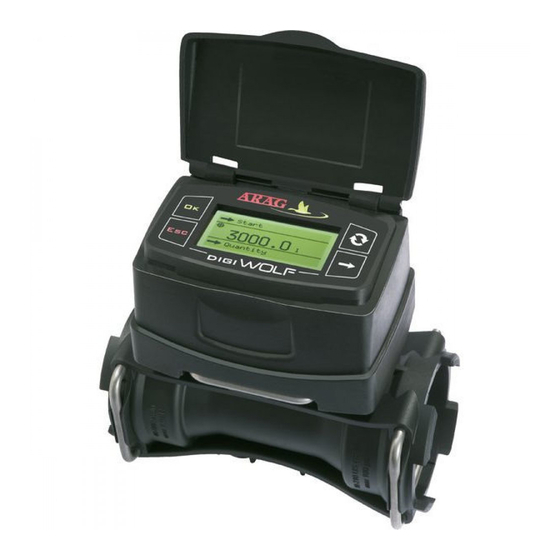
digi
FlUssOMETRO A pAlETTE / pADDlE FlOWMETER
MEDIDOR DE cAUDAl DE pAlETAs
FlUxôMETRO DE pAlhETA / DébITMèTRE à pAlETTEs
1
OK
OK
2
3
APPROXIMATE CONSTANT
XXX
APPROXIM
XXX
ATE CONSTAN
T
4
La direzione delle frecce sul corpo devono corrispondere a quella posta sull'etichetta
Arrows direction on the body must correspond to the one on the label
La dirección de las flechas en el cuerpo deben corresponder a la colocada en la etiqueta
A direção das setas no corpo devem corresponder àquela colocada na etiqueta
La direction des flèches sur le corps doivent correspondre à celle placée sur l'étiquette
AP PR
OX IMA
TE CO
X X X
NS TA
NT
5
6
7
Non disperdere le pile esaurite nell'ambiente. Smaltirle nell'apposito contenitore.
Do not dispose of exhausted batteries in the environment. Dispose of in a suitable container.
No desechar las pilas usadas en el ambiente. Utilizar de los contenedores adecuados.
Não descarte as pilhas gastas no meio ambiente. Elimine-as no recipiente adequado.
Ne jetez pas les piles épuisées dans l'environnement. Déposez-les dans un récipient adapté.
D20248-m01
06/2011
1
DESTINAZIONE D'USO
Questo dispositivo è progettato per l'installazione su macchine agricole per diserbo e irrorazione.
Il flussometro non deve essere assolutamente usato per misurare il passaggio di idrocarburi, liquidi infiammabili, esplosivi o tossi-
ci. Il flussometro non è adatto al contatto con liquidi alimentari.
GUIDA DI RIFERIMENTO
2
INSTALLAZIONE
REFERENcE GUIDE
Installate il flussometro ad almeno 20 cm da elementi che possano causare turbolenze all'interno del condotto (valvole, curve, strozzature, etc.).
GUíA DE REFERENcIA
Il flussometro può essere installato in posizione orizzontale o verticale.
ATTENZIONE:
GUIA DE REFERêNcIA
- Non montate il flussometro con il connettore rivolto verso il basso (Fig. 1).
MANUEl DE RéFéRENcE
- PER UN CORRETTO FUNZIONAMENTO, L'IMPIANTO DOVRÀ PREVEDERE UN SISTEMA DI FILTRAGGIO CON FILTRO DI ALMENO
50 MESH, E UNA VALVOLA DI SICUREZZA CHE LIMITI LA PRESSIONE DI UTILIZZO ALLA MASSIMA PREVISTA (Tab. 1).
Montate il flussometro mediante gli appositi fissaggi (Fig. 2): inserite i bulloni (M8) nelle sedi previste, quindi farli scorrere nella posizione di
OK
NO!
fermo per impedirne la fuoriuscita.
Il corpo del flussometro dovrà essere montato con la freccia dell'etichetta rivolta verso la direzione del flusso (Fig. 4).
2.1 Alimentazione (Fig. 7)
DigiWolf è alimentato da 2 pile AA tipo LR6 (alcaline) o FR6 (Li-Fe S2), non incluse.
2.2 Connessioni idrauliche per raccordi forchetta / ottone
CODICE
l/min.
10-200
4628405
20-400
4628506
4628707
40-800
Il diametro indicato in pollici (Ø equivalente) è riportato a puro scopo indicativo del passaggio tipico del corpo del flussometro.
In realtà possono essere scelte misure differenti a seconda del raccordo a forchetta utilizzato.
3
IMPOSTAZIONI PRELIMINARI ALL'USO
A causa delle diverse configurazioni dell'impianto (tubazioni, valvole, etc.) la costante potrebbe non essere corretta.
Si raccomanda di eseguire una prova di erogazione; nel caso in cui il valore misurato dovesse essere diverso dal valore reale, si
consiglia di agire sulla costante di portata eseguendo una procedura di calibrazione automatica oppure calcolando manualmente la
costante stessa (vedi manuale completo nel CD allegato al prodotto).
Alla prima accensione, il DigiWolf eseguirà una procedura guidata per l'impostazione della lingua e delle due unità di misura (portata e volume).
Italiano
B
English
Español
Português
C
4
MANUTENZIONE
4.1 Pulizia e sostituzione paletta (Fig. 3)
1) Sfilate mediante un cacciavite la forchetta dal monitor.
2) Estraete il monitor dal corpo del flussometro.
3) Svitate la ghiera in senso antiorario ed estraete il blocco portasensore dal corpo del flussometro.
4) Estraete il gruppo paletta dal blocco portasensore mediante una semirotazione in senso antiorario.
5) Immergete il gruppo paletta in un liquido detergente per alcune ore.
6) Lavate accuratamente il gruppo paletta con acqua corrente e verificatene il corretto funzionamento. Se necessario, sostituite l'intero
gruppo paletta con l'apposito ricambio (cod. 4626000.500).
7) Rimontate il gruppo paletta sul sensore elettronico mediante una rotazione in senso orario fino allo scatto.
8) Rimontate il blocco portasensore sul corpo del flussometro avvitando la ghiera in senso orario fino a finecorsa FACENDO ATTENZIO-
NE CHE LA FRECCIA INDICATA SUL MANICOTTO SIA ORIENTATA NELLA DIREZIONE DEL FLUSSO (Fig. 4).
4.2 Sostituzione degli O-Ring
Con il blocco portasensore sfilato (vedi Par. 4.1) procedete come segue:
1) Sfilate mediante un cacciavite la forchetta dalla ghiera (Fig. 5).
2) Sfilate il girello (Fig. 6).
- Sostituzione O-Ring:
Sostituite gli O-Ring (cod. G10051V - rif. catalogo ricambi ARAG).
3) Riassemblate il gruppo sensore, facendo attenzione che la forchetta sia correttamente inserita nel girello.
5
DATI TECNICI
Alimentazione
Assorbimento massimo
Temperatura di esercizio
Temperatura di stoccaggio
Peso (pile escluse)
Ø equivalente
P max
P max
US GPM
Attacco
(inch)
(bar)
(PSI)
2.6-53
T5 F
1 1/4"
20
290
5-106
T6 F
1 1/2"
12
174
10-210
T7 F
2"
7
130
Tab. 1
A Premete per spostarvi tra le voci
B Premete per confermare la voce desiderata
Language
C Premete per tornare alla schermata precedente senza salvare
A
Per tutte le altre impostazioni, consultate il manuale completo.
: 2 pile AA tipo LR6 (alcaline) o FR6 (Li-Fe S2)
: 40 mA (retroilluminazione al 100%) / 4.7uA (standby)
: 0 °C ÷ 50 °C / +32 °F ÷ +122 °F
: 0 °C ÷ 50 °C / +32 °F ÷ +122 °F (pile inserite) / -30 °C ÷ 80 °C / -22 °F ÷ +176 °F (senza pile)
: 680 ÷ 750 g (a seconda del modello)
ITALIANO
1
INTENDED USE
This device is designed to work on agricultural machinery for crop spraying applications.
The flowmeter must not be used to measure the passage of hydrocarbons, flammable, explosive or toxic liquids. The flowmeter is
not suitable for contact with liquids for human consumption.
2
INSTALLATION
Install the flowmeter at least 20 cm from the elements that could cause turbulence inside the tubes (valves, bends, constrictions, etc.).
The flowmeter can be installed in a vertical or horizontal position.
CAUTION:
- Do not install the flowmeter with the connector facing downwards (Fig. 1).
- THE SYSTEM MUST HAVE A FILTERING ELEMENT WITH A FILTER OF AT LEAST 50 MESH, TOGETHER WITH A SAFETY VALVE TO
LIMIT USE PRESSURE AT THE SPECIFIED MAX. VALVE (Tab. 1).
Assemble the flowmeter using the suitable mounting parts (Fig. 2): fit the bolts (M8) in their seats, then make them slide to their stop position
to prevent them from coming out.
The flowmeter body must be assembled with the arrow on the label facing the flow direction (Fig. 4).
2.1 Power supply (Fig. 7)
DigiWolf is powered by 2 AA batteries type LR6 (alkaline) or FR6 (Li-Fe S2), not included.
2.2 Hydraulic connection for brass/fork connections
CODE
l/min.
US GPM
Connection
10-200
2.6-53
T5 F
4628405
4628506
20-400
5-106
T6 F
4628707
40-800
10-210
T7 F
The diameter in inches (Ø equivalent) is given only as an indication of the typical passage of the flowmeter body. Actually, it is pos-
sible to choose different sizes depending on the fork connection used.
3
PRELIMINARY SETUP FOR USE
Rate reading may not be correct due to different system configurations (tubes, valve, etc.). Therefore, we recommend to make a
spray test; in case the measured value is different from the real one, perform an automatic calibration procedure or manually calcu-
late flowrate constant (see complete manual in the CD supplied with the product).
Upon first switch on DigiWolf carries out a guided procedure to setup the language and the two units of measurement (flowrate and volume).
Language
Italiano
B
English
Español
Português
C
4
MAINTENANCE
4.1 Paddle cleaning and replacement (Fig. 3)
1) Remove the fork from the monitor using a screwdriver.
2) Remove the monitor from the flowmeter body.
3) Unscrew the ring nut in a counter clockwise direction and remove the sensor housing block from the flowmeter body.
4) With half a rotation, remove the paddle group from the sensor housing block in a counter clockwise direction.
5) Immerse the paddle group in detergent liquid for several hours.
6) Wash the paddle group thoroughly with running water and check its correct operation. If necessary, replace the complete paddle group
with its suitable spare part (code 4626000.500).
7) Refit the paddle group on the electronic sensor with a clockwise rotation until it clicks in place.
8) Refit the sensor housing block on the flowmeter body tightening the ring nut in a clockwise direction until it stops PAYING ATTENTION
TO KEEP THE ARROW ON THE COUPLING FACING THE FLOW DIRECTION (Fig. 4).
4.2 OR replacement
With the removed sensor housing block (see Par. 4.1) proceed as follows:
1) Remove the fork from the ring nut using a screwdriver (Fig. 5).
2) Remove the ring nut (Fig. 6).
- OR replacement:
Replace the ORs (code G10051V - ARAG spare parts catalogue).
3) Refit the sensor housing block ensuring that the fork is correctly inserted in the ring nut.
5
TECHNICAL DATA
Power supply
: 2 AA batteries type LR6 (alkaline) or FR6 (Li-Fe S2)
Max. absorption
: 40 mA (100% backlight) / 4.7uA (standby)
Working temperature
: 0 °C ÷ 50 °C / +32 °F ÷ +122 °F
Storage temperature
: 0 °C ÷ 50 °C / +32 °F ÷ +122 °F (with batteries) / -30 °C ÷ 80 °C / -22 °F ÷ +176 °F (without batteries)
Weight (without batteries)
: 680 ÷ 750 g (depending on the type)
ENGLISH
Ø equivalent
Max. p
Max. p
(inch)
(bar)
(PSI)
1 1/4"
20
290
1 1/2"
12
174
2"
7
130
Tab. 1
A Press to toggle from one item to another
B Press to confirm the desired item
C Press to go back to the previous page without saving
A
Consult to the complete manual for all other settings.
Advertisement

Subscribe to Our Youtube Channel
Related Manuals for ARAG DigiWOLF


Summary of Contents for ARAG DigiWOLF
- Page 1 (vedi manuale completo nel CD allegato al prodotto). Upon first switch on DigiWolf carries out a guided procedure to setup the language and the two units of measurement (flowrate and volume). Alla prima accensione, il DigiWolf eseguirà una procedura guidata per l’impostazione della lingua e delle due unità di misura (portata e volume).
- Page 2 (voir le manuel complet sur le CD fourni avec le produit). Durante el primer encendido, el DigiWolf realizará un procedimiento guiado para la programación del idioma y de la unidad de medida (caudal y No primeiro acendimento, o DigiWolf efetuará um procedimento guiado para a configuração da língua e das duas unidades de medição (vazão e Au premier allumage, le DigiWolf exécute une procédure guidée pour programmer la langue et les deux unités de mesure (débit et volume).
Need help?
Do you have a question about the DigiWOLF and is the answer not in the manual?
Questions and answers