ARAG VISIO Manual
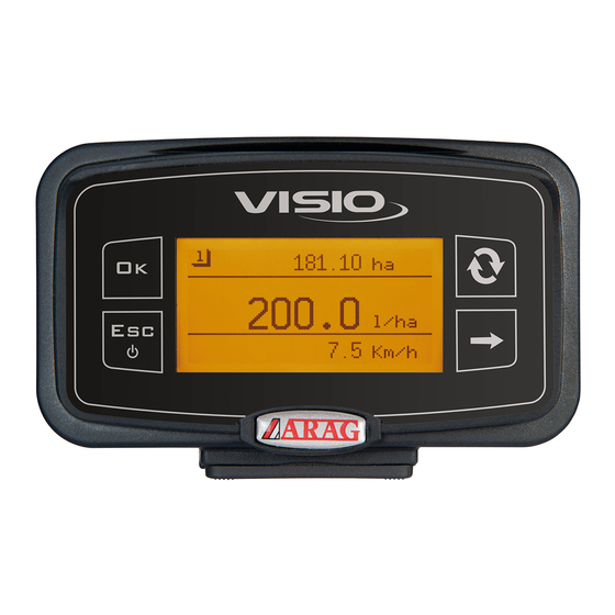
Rpm indicator + surface version
Hide thumbs
Also See for VISIO:
- Installation, use and maintenance manual (24 pages) ,
- Manual (31 pages) ,
- Installation, use and maintenance manual (20 pages)
Table of Contents
Advertisement
Advertisement
Table of Contents

Subscribe to Our Youtube Channel
Related Manuals for ARAG VISIO


Summary of Contents for ARAG VISIO
- Page 1 RPM INDICATOR + SURFACE VERSION Software rel. 2.3.x...
-
Page 2: Table Of Contents
CONTENTS ● Legend of symbols ..................... 3 INTRODUCTION ......................4 Product description ....................4 INTENDED USE ......................4 CONTENT OF THE PACKAGE ..................4 PRECAUTIONS ......................4 RISKS AND PROTECTIONS BEFORE ASSEMBLY ............ 5 Positioning ........................5 Power supply and sensor connection ................ 5 ASSEMBLY DIAGRAMS ....................6 CONTROLS IN THE MENU ................... 7 First switching on ....................... -
Page 3: Legend Of Symbols
This manual is an integral part of the equipment to which it refers and must accompany the equipment in case of sale or change of ownership. Keep it for any future reference; ARAG reserves the right to modify product specifications and instructions at any moment and without notice. -
Page 4: Introduction
a n d Instruction manual connection cables (on CD-ROM) t o b e c o n n e c t e d Installation sheet to VISIO must be ordered separately. PRECAUTIONS • Do not aim water jets at the equipment. • Do not use solvents or fuel to clean the case outer surface. • Do not clean equipment with direct water jets. -
Page 5: Risks And Protections Before Assembly
Positioning 1) Set mounting rail in cabin and fasten it with the relevant screws (1), in a position where VISIO can be easily seen and at hands' reach, but away from any moving organs. 2) Secure VISIO to rail and push down until locked in place. -
Page 6: Assembly Diagrams
ASSEMBLY DIAGRAMS +12Vdc Counting abort Connection +12VDC (yellow wire) Counting abort Ground connection (green wire) Legend: 1) Power cable 2) Connection cable for double sensor 3) RPM sensor 4) Speed sensor... -
Page 7: Controls In The Menu
CONTROLS IN THE MENU First switching on At first switching on, VISIO will run a guided procedure allowing user to set the device's basic settings. Press to scroll through items, to save and move on to next setting, or to go back to previous setting. WARNING: Before changing operating mode, make sure that all sensors / flowmeters are DISCONNECTED from the device. -
Page 8: Controls In The Menu
Controls in the menu In the following pages, according to the set operating mode, some menu items could slightly differ from the shown ones. SWITCHING ON A Press for 1 second B Press the key a few times to view the various values in extended mode, (on display central part) Every time the device is switched on, it will shortly show a page with the name of device and software version. SWITCHING OFF A Press for 2 seconds ACCESS TO SETUP MENU From the main page, press keys at the same time for 2 seconds to open the Setup Menu. - Page 9 SELECTION AND ACCESS TO MENU ITEMS A Press a few times to scroll through items (selected item is indicated by a black line) B Press to open the selected menu item The three dots under an item indicate presence of another setup menu. EDITING A VALUE A Press to move through digits B Press a few times to edit the highlighted digit C Press to confirm. The display goes back to previous page D Press to exit page without confirming modification Edited value must fall within the range shown.
-
Page 10: Menu Structure
MENU STRUCTURE... -
Page 11: Preliminary Setup For Use
PRELIMINARY SETUP FOR USE Speed alarms Set minimum and maximum speed thresholds for alarm message. 1) Open Alarm menu (Setup menu > Alarms). Minimum and maximum speed alarms are set in the same way. The display will show the current setting below the selected item. Press to edit the selected menu item. 2) To activate the alarm, press and key at the same time until message OFF goes off and speed alarm value is displayed instead. Carry out the same procedure to disable alarm again. 3) Set alarm value: A) Press to move through digits. B) Press a few times to edit the highlighted digit. C) Press to save changes, or D) Press to quit the page without confirming changes. -
Page 12: Sensors
Sensors 1) Open Sensors menu (Setup menu > Sensors). The menu items displayed below change according to the set operation mode: when more items are available, select the desired one and press to edit it. -
Page 13: Speed Sensor Calibration
Speed sensor calibration VISIO calculates the information concerning the speed thanks to pulses received by the sensor installed on the wheel. To perform calibration, proceed as follows: - Measure a straight path at least 100 m (300 feet) long. The longer the distance traveled, the more accurate the wheel constant calculation. - Take measurements with tyres at the operating pressure. This test must be performed on medium-hard terrain; for application to very soft or very hard terrain, rolling diameter may vary, leading to inaccurate output calculation; when this is the case, repeat the procedure. During the test, cover the distance with the tank filled up to half capacity with water. - Page 14 Automatic calibration Calculate and save the wheel constant according to the procedure below: 1) Open automatic calibration menu (Setup menu > Sensors > Speed sensor > Auto Calibration). As soon as menu is open, the equipment is ready to start measuring with no further controls being required. Cover the requested distance: the number of pulses will increase during the path and the bottom area will indicate instant speed reading. Stop the tractor at the end of the distance. If a malfunction occurs, the message Check sensor! will be shown in the top part of the display. Press to stop the counting. The display will go back to the previous menu and will show the acquired value. In case of measurement errors, or if it is necessary to stop the calibration, press for 2 seconds to quit the calibration procedure without saving. In this case, the value will be the one previously measured, or the default value.
- Page 15 Manual calibration Manual calibration allows to enter the wheel constant value calculated with the suitable formula: distance traveled (cm) Kwheel = no. of detection points x wheel rpm distance traveled < > distance expressed in cm covered by the wheel along measurement travel;...
-
Page 16: Language
Language Set the desired language. Open language setting menu (Setup menu > Options > Language). Options The display will show the current Language English setting below the selected item. Units of measurem. Display contrast Press to edit language. 1) Select a language through Language Česk Deutsch 2) Press to save, or to quit English Español without saving. -
Page 17: Units Of Measurement
Units of measurement Set unit of measurement for the values detected by the device. Speed unit of measurement Open speed unit of measurement setting menu (Setup menu > Options > Units of measurem. > Speed). The display will show the current setting below the selected item. Press to select speed unit of measurement. 1) Select a unit through 2) Press to save, or to quit without saving. Length units of measurement Open length unit of measurement setting menu (Setup menu > Options > Units of measurem. > Length). The display will show the current setting below the selected item. Press to select length unit of measurement. 1) Select a unit through 2) Press to save, or to quit without saving. - Page 18 Surface units of measurement Open surface unit of measurement setting menu (Setup menu > Options > Units of measurem. > Surface). The display will show the current setting below the selected item. Press to select surface unit of measurement. 1) Select a unit through 2) Press to save, or to quit without saving. Distance units of measurement Open distance unit of measurement setting menu (Setup menu > Options > Units of measurem. > Distance). The display will show the current setting below the selected item. Press to select distance unit of measurement. 1) Select a unit through 2) Press to save, or to quit without saving.
-
Page 19: Display Contrast
Display contrast Set display contrast. Open display contrast menu (Setup menu > Options > Display contrast). The display will show the current setting below the selected item. Press to edit the selected menu item. 1) Set a value through . Every time you press it, value will increase by 5% up to 100%. Use key to decrease value by 5%. 2) Press to save, or to quit without saving. -
Page 20: Alarm Tones
Alarm tones Enable/disable the alarm tones. Open alarm tones menu (Setup menu > Options > Alarm tones). The display will show the current setting below the selected item. Press to edit the selected menu item. 1) Set status through 2) Press to save, or to quit without saving. Keytones Enable/disable keytones. 1) Open keytones menu (Setup menu > Options > Keytones). The display will show the current setting below the selected item. Press to edit the selected menu item. 1) Set status through 2) Press to save, or to quit without saving. -
Page 21: Display Settings
Display settings The main page shows the display divided into three horizontal parts, which can be separately reset (according to the value). Every sector can be assigned the desired value: - TOT 1-2 surf. = Total surface covered; - TOT distance = Total distance covered; - Speed = Detected instant speed; - Rpm sensor 1 = Rpm live reading; - Min. Rpm sens. 1 = minimum detected Rpm; - Max. Rpm sens. 1 = maximum detected Rpm; - RPM sens. time 1 = value, measured in seconds, during which VISIO has detected a movement of the rotating part. Open Display settings menu (Setup menu > Options > Display settings). Press to edit the selected menu item. 1) Select value through 2) Press to edit, or to quit without saving. 1) Set sector to the required value through 2) Press to save, or to quit without saving. Carry out the same procedure for the other 2 values. -
Page 22: Boom Length
Boom length Set boom length. 1) Open the boom length menu (Setup menu > Options > Boom length). The display will show the current setting below the selected item. Press to edit the selected menu item. 2) Set boom length: A) Press to move through digits. B) Press a few times to edit the highlighted digit. C) Press to save changes, or D) Press to quit the page without confirming changes. -
Page 23: Operating Mode
Operating mode Set required operating mode. Open operating mode menu (Setup menu > Options > Operating mode). The display will show the current setting below the selected item. Press to change the operating mode. 1) Select the required operating mode through 2) Press to save, or to quit without saving. WARNING: Once is pressed, the page on twhe side will be displayed. Before changing operating mode, make sure that all sensors are DISCONNECTED from the device. Press to confirm changes. Connect the sensors REQUIRED FOR THE SET OPERATING MODE. -
Page 24: Setup Management
Setup management VISIO settings can be loaded from or saved on a USB pen drive in order to reconfigure it if required, fix problems or set another VISIO with no need to repeat all manual operations. Once installation is completed, and VISIO operation has been checked, we recommend to save all settings onto a USB pen drive. To be able to use the following functions it is necessary to insert a USB pen drive in the relevant port at the bottom of VISIO. 1) Open Setup management menu (Setup menu > Setup management). Press to edit the selected menu item. Load setup Allows to select a configuration file saved in the USB pen drive and to set VISIO again. WARNING: By loading the SETUP.BIN file contained in the USB pen drive onto the VISIO, all current settings will be lost. 1) Select the desired control through key. 2) Press to confirm loading, or to quit without saving. The SETUP.BIN file can be loaded only if it is saved in the USB pen drive root directory. If setup download involves changing operating mode and using different sensors than the ones in use, make sure that all sensors are DISCONNECTED from the device. Press to confirm loading. Reconnect sensors. - Page 25 Save setup Allows saving VISIO configuration file on the USB pen drive: it will be possible to load it again any time the same settings need to be retrieved. 1) Select the desired control through key. 2) Press to confirm saving, or to quit without saving. If a SETUP.BIN file is already present in the USB pen drive root directory, the file will be overwritten.
-
Page 26: Test Menu
Test menu This menu allows user to view some data and carry out an operation test of VISIO: - Firmware version: the display shows the firmware version installed. - Battery voltage: the display shows the power voltage of the device. Display test Display test checks the device display correct operation. 1) Open display test menu (Setup menu > Test > Display). Press to perform the test. All pixels on display are turned on. Press to go back to previous page. Keys test Keys test checks the device keys correct operation. Open keys test menu (Setup menu > Test > Keys). Press to perform the test. 1) Press any key and the corresponding display area will turn on. Press to quit: as soon as you acknowledge the switch-on on of the corresponding area on the display, device will go back to previous page. - Page 27 Sensors test Sensors test checks correct operation of the sensors connected to the device. Open sensors test menu (Setup menu > Test > Sensors). Press to perform the test. The display will show the current sensor reading below the selected item. 1) Several sensors could be displayed, depending on the set operating mode. In this case, select required sensor through 2) Press to quit.
-
Page 28: Use
Depending on set data, activate the rotating part, or start the vehicle. The display will start showing the detected value. Partial totalizer reset To reset a peak value or a totalizer, it is necessary to view it in extended mode. Press key several times until value to be reset is at the central area of the display. Press for two seconds. The value resets. Symbol ----- indicates that the value exceeds the maximum value that can be displayed. Totalizers display maximum 4 digits. -
Page 29: Maintenance / Diagnostics / Repairs
MAINTENANCE / DIAGNOSTICS / REPAIRS • Clean only with a soft wet cloth. • Do not use aggressive detergents or products. • Do not clean equipment with direct water jets. Troubleshooting FAULT CAUSE REMEDY Check power cable No power supply connections VISIO is off or does not switch on Device is OFF Press the ON key Check displayed data Wrong setup setup VISIO shows wrong data Sensor fault Contact the nearest Assistance Center VISIO fault Filling pump (if any) does Pump Stop Module not Check power supply not start powered connection END OF LIFE DISPOSAL Dispose of the system in compliance with the established legislation in the country of use. -
Page 30: Technical Data
TECHNICAL DATA Device technical data Description VISIO Display Graphic LCD, 128 x 64 pixels, back-lighting Power supply voltage 9 ÷ 16 Vdc Protection against short-circuit • Protection against polarity inversion • Max. frequency 1.2 KHz Analog inputs 4 ÷ 20 mA Digital output - Max current 100 mA Maximum power input (with no 160 mA sensors connected) -20 °C ÷ 70 °C Operating temperature -4 °F ÷ +158 °F -30 °C ÷ 80 °C Storage temperature -22 °F ÷ +176 °F Size 126 x 79 x 66 mm Weight 245 g... -
Page 31: Setup Menu
Setup menu Data Min. Max. Default UoM Notes Sensor Calibration 200.0 60.0 pls/l Alarm can be disabled by setting Min. speed km/h value to "OFF" Alarm can be disabled by setting Max. speed km/h value to "OFF" Alarms Alarm can be disabled by setting Min. Rpm 9999 value to "OFF" Alarm can be disabled by setting Max. Rpm 9999 value to "OFF" Display Contrast Available languages: Italiano, English, Español, Português, Language English Français, Deutsch, Cesky, Polski, Русский, Magyar, Speed units of Available units of measurement: km/h measurement km/h, MPH Options... -
Page 32: Guarantee Terms
GUARANTEE TERMS ARAG s.r.l. guarantees this apparatus for a period of 360 days (1 year) from the date of sale to the client user (date of the goods delivery note). The components of the apparatus, that in the unappealable opinion of ARAG are faulty due to an original defect in the material or production process, will be repaired or replaced free of charge at the nearest Assistance Center operating at the moment the request for intervention is made. The following costs are excluded: disassembly and reassembly of the apparatus from the original system; transport of the apparatus to the Assistance Center. The following are not covered by the guarantee: damage caused by transport (scratches, dents and similar); damage due to incorrect installation or to faults originating from insufficient or inadequate characteristics of the electrical system, or to alterations resulting from environmental, climatic or other conditions; damage due to the use of unsuitable chemical products, for spraying, watering, weedkilling or any other crop treatment, that may damage the apparatus; malfunctioning caused by negligence, mishandling, lack of know how, repairs or modifications carried out by unauthorized personnel; incorrect installation and regulation; damage or malfunction caused by the lack of ordinary maintenance, such as cleaning of filters, nozzles, etc.; anything that can be considered to be normal wear and tear. Repairing the apparatus will be carried out within time limits compatible with the organizational needs of the Assistance Center. No guarantee conditions will be recognized for those units or components that have not been previously washed and cleaned to remove residue of the products used; Repairs carried out under guarantee are guaranteed for one year (360 days) from the replacement or repair date. ARAG will not recognize any further expressed or intended guarantees, apart from those listed here. No representative or retailer is authorized to take on any other responsibility relative to ARAG products. The period of the guarantees recognized by law, including the commercial guarantees and allowances for special purposes are limited, in length of time, to the validities given here. In no case will ARAG recognize loss of profits, either direct, indirect, special or subsequent to any damage. The parts replaced under guarantee remain the property of ARAG. All safety information present in the sales documents regarding limits in use, performance and product characteristics must be transferred to the end user as a responsibility of the purchaser. - Page 33 CONFORMITY DECLARATION The declaration of conformity is available at www.aragnet.com, in the relevant section.
- Page 34 Only use genuine ARAG accessories or spare parts to make sure manufacturer guaranteed safety conditions are maintained in time. Always refer to the internet address www.aragnet.com 42048 RUBIERA (Reggio Emilia) - ITALY Via Palladio, 5/A Tel. +39 0522 622011 Fax +39 0522 628944 www.aragnet.com...
Need help?
Do you have a question about the VISIO and is the answer not in the manual?
Questions and answers