Delta DPA Series Instruction Sheet
Hide thumbs
Also See for DPA Series:
- Instruction sheet (9 pages) ,
- Instruction sheet (9 pages) ,
- Instruction sheet (9 pages)
Advertisement
Quick Links
Series Pressure Sensor
Instruction Sheet
Thank you very much for choosing Delta DPA series pressure sensor. Please read this instruction sheet carefully before
using your DPA. Keep this instruction sheet handy for quick reference.
Warning
DANGER! CAUTION! ELECTRIC SHOCK!
DPA is a pressure measurement device. DO NOT use it out of its specification. Improper pressure or
incorrect wiring may cause series injuries on staff or damages on other devices.
1. Keep away from high-voltage and high-frequency environment during the installation in case of interference.
Prevent using the device in premises which contain:
(a) dust or corrosive gas; (b) high humidity and high radiation; (c) shock and vibration.
2. DPA can only be used for air pressure measurement and should avoid corrosive, inflammable or toxic gas
measurement.
3. Make sure the power supply is switched off when installing or dismounting DPA and the pressure source stops its
action in case harms occur on human body and properties.
4. DO use parts compatible to the specification of the pressure pore for connection to avoid mistaken measurement or
safety problems.
5. Before switching on the power supply, check the signal connection, e.g. the input voltage and polarity. Voltage that is
too high may cause damages on DPA.
6. DO use dry cloth and DO NOT use acid or alkaline liquid to clean the device.
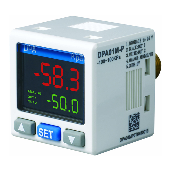
Product Profile & Outline
1. Analog output indicator
6. UP key
2. Digital output 1 indicator
7. SET key
3. Digital output 2 indicator
8. DOWN key
4. Pressure/parameter display
9. Power supply and output terminals
5. SV/setup item display
10. Pressure input pore
Contents in the pack: Pressure sensor, signal wire, unit sticker, instruction sheet
Optional accessories: Panel mounting parts, metal mounting parts
Ordering Information
Series name
DPA: Delta DPA series pressure sensor
1 2
01: -100kPa ~ 100kPa
10: -100kPa ~ 1,000kPa
Measurable pressure range
N: NPN output + 4 ~ 20mA; P: PNP output + 4 ~ 20mA
3
Output types
M: NPN output + 1 ~ 5V; Q: PNP output + 1 ~ 5V
P: Outer pore 1/8 PT, inner pore M5;
4
Pressure pore types
N: Outer pore 1/8 NPT, inner pore M5
Electrical Specifications
Voltage range
12 ~ 24V DC +/- 10% no isolation
Power supply
Power consumption
40mA Max.; current output type 60mA Max.
Pressure type
Non-corrosive gas, gauge type
DPA01: -100kPa ~ 100kPa
Measurable range
DPA10: -100kPa ~ 1,000kPa
Pressure
DPA01: 200kPa
measurement
Max. durable pressure
DPA10: 1,500kPa
Accuracy
+/- 3% entire process
Temperature inaccuracy
+/- 2% entire process
Setup display
2-line LCD display, 4 digits for measured value and 3.5 digits for setup display
Status display
LCD output status display
Display
Display mode
3 colors for different modes
Cycle
250ms, 500ms, 1,000ms
Number of outputs
Built-in 2 NPN or PNP transistor digital outputs and 1 analog output
NPN: Max. durable pressure 30V/100mA, residual voltage 1.5V
Transistor output
PNP: Max. durable pressure 30V/100mA, residual voltage 1.5V
Output
1 ~ 5V: Min. output load resistance 1,000Ω
Analog output
4 ~ 20mA: Max. output load resistance 400Ω; linear inaccuracy < 2% entire process
Response time
2ms, 4ms, 10ms, 30ms, 50ms, 100ms, 250ms, 500ms, 1,000ms, 5,000ms
Output inaccuracy
Linear inaccuracy: < +/- 2% entire process
P
Outer diameter PT 1/8, inner diameter M5
Pore size
N
Outer diameter NPT 1/8, inner diameter M5
R
Outer diameter Rc 1/8, inner diameter M5
Shock immunity
10 ~ 500Hz, 10mm 3 axes for 2 hours
2
Vibration immunity
Max. 100m/ s
3 axes 6 directions, 3 times each
Ambient temperature
0°C ~ +50°C
Storage temperature
-20°C ~ +65°C
Altitude
< 2,000m
Ambient humidity
35% ~ 80% RH (non-condensing)
How to Set up Parameters
Switching modes: DPA will be in the "Measuring Mode" when it is switched on, displaying PV and SV. Press
more than 2 seconds in this mode to switch to the "Quick Setup Mode". Press
"measuring mode" to switch to "Advanced Setup Mode". Press
in the "Quick Setup Mode" or "Advanced Setup
Mode" to return to the "Measuring Mode".
Setting up parameters: In the three modes, press
once to select the parameter to set up. When you find the
parameter to be set up or modify, use
to modify the setting.
Switching on DPA
Press
> 4 secs.
Press
Advance Setup
Measuring Mode
Mode
Press
> 2 secs.
Quick Setup Mode:
Quick Setup
OUT1 mode
(See "Output Mode Setting" for details.)
Easy
Hysteresis
Window
OUT2 mode
(See "Output Mode Setting" for details.)
Easy
Hysteresis
Window
NO/NC of
OUT1, OUT2
OUT1 N.O.
OUT1 N.C.
OUT1 N.O.
OUT2 N.O.
OUT2 N.O.
OUT2 N.C.
Output response time
PV display color
Red
OUT LED ON: red
OUT LED ON: green
OUT LED OFF: green
OUT LED OFF: red
Unit
2
MPa*
kPa
kgf/cm
inchHg
*: Will not be displayed in low pressure type sensor.
Advanced Setup Mode:
Advanced Setup
Auxiliary display
(Change SV display method)
Display SV
OFF
Display unit
Displayed speed
Hysteresis
Power saving
(Close backlight)
Switching color
display
Code
Copy mode
Analog output
switch
Returning to
default setting
Measuring Mode:
Measuring
Upper limit of
OUT1
for
Lower limit of
for more than 4 seconds in the
OUT1
Upper limit of
OUT2
Lower limit of
OUT2
> 4 secs.
Quick Setup
Mode
Press
> 4 secs.
Quick Setup Mode
Set up OUT1 mode
Press
Set up OUT2 mode
Press
Set up N.O./N.C. of OUT1
and OUT2
OUT1 N.C.
OUT2 N.C.
Press
(Unit: ms)
Set up output response time
Green
Press
Set up PV display color
bar
psi
mmHg
Press
Set up unit
Press
Return to "set up
OUT1 mode"
(Unit: ms)
Initial Setting
(Used with "PV display color")
1.
Units: DPA provides many units for users, including kPa, kgf/cm
you can press
(See "Code" for details.)
Slave mode
Master mode
Set OUT1 to
Set OUT1 to easy
hysteresis or window
or window mode
mode
Display
in turn
SV
SV
Display
in turn
Set OUT 2 to
Set OUT2 to easy
hysteresis or
mode
window mode
Advanced Setup Mode
Measuring Mode
Set up auxiliary display
Set up upper limit of OUT1
(Change SV display method)
(Set OUT1 to hysteresis mode /
window mode)
Press
Press
Set up displayed speed
Set up lower limit of OUT1
(Set OUT1 to hysteresis mode /
window mode)
Press
Press
SV of OUT1
Set up hysteresis
(Set OUT1 to easy mode)
Press
Press
Set up power saving mode
Set up upper limit of OUT2
(Set OUT2 to hysteresis mode /
window mode)
Press
Press
Set up switching color
Set up lower limit of OUT2
referencing output items
(Set OUT2 to hysteresis mode /
window mode)
Press
Press
SV of OUT2
Set up code
(Set OUT2 to easy mode)
Press
Press
Set up copy function
Press
Set up analog output switch
Press
Return to default settings
Press
Return to "set up
auxiliary display"
2
, bar, psi, mmHg and inchHg. In the easy mode,
and find
to set the unit to the desired one.
Returning to output
setting
Advertisement

Subscribe to Our Youtube Channel
Related Manuals for Delta DPA Series


Summary of Contents for Delta DPA Series
- Page 1 Pore size Outer diameter NPT 1/8, inner diameter M5 Returning to Thank you very much for choosing Delta DPA series pressure sensor. Please read this instruction sheet carefully before Outer diameter Rc 1/8, inner diameter M5 default setting using your DPA. Keep this instruction sheet handy for quick reference.
- Page 2 4. Analog output signal (orange) 250 ms 5. Negative power supply input (blue) OUT1 or OUT2 500 ms The content of this instruction sheet may be revised without prior notice. Please consult our distributor or download the most updated version at http://www.delta.com.tw/industrialautomation.
Need help?
Do you have a question about the DPA Series and is the answer not in the manual?
Questions and answers