
Subscribe to Our Youtube Channel
Related Manuals for Delta InfraSuite RWD030R


Summary of Contents for Delta InfraSuite RWD030R
- Page 1 The power behind competitiveness Delta InfraSuite Precision Cooling RowCool Air Cooled Type (RWD030R) User Manual www.deltapowersolutions.com...
- Page 2 Failure to heed these instructions and warnings will void the warranty. Copyright © 2021 by Delta Electronics Inc. All Rights Reserved. All rights of this User Manual (“Manual”), including but not limited to the contents, information, and figures are solely owned and reserved by Delta Electronics Inc.
-
Page 3: Table Of Contents
Table of Contents Chapter 1 : Safety Instructions ....................5 General ........................5 Installation Warnings ..................... 5 Operation Warnings ....................6 Chapter 2 : Introduction ......................7 Package List ......................7 ... - Page 4 Pre-start Inspection ....................51 Power On ......................52 Charging Refrigerant ................... 53 Chapter 5 : Operation ......................55 Main Page ......................55 Account Authority and Login ................56 How to Operate the Main Page ................58 ...
-
Page 5: Chapter 1 : Safety Instructions
Chapter 1 : Safety Instructions General Carefully read all chapters of the Manual before any installation, operation, or maintenance. To avoid personal injuries and damaging the equipment, be sure to operate the product in accordance with the instructions in this Manual and the markings on the cabinet. -
Page 6: Operation Warnings
Operation Warnings Please read these operating instructions before operation. The high voltage and high-pressure in the equipment can cause personal injuries! The components may have hidden dangers and only authorized service personnel can operate the unit. Improper operation may lead to serious injury or death or equipment damage. -
Page 7: Chapter 2 : Introduction
Outdoor Unit: It includes the outdoor unit and an accessory pack. The accessory bag includes objects shown in Figure 2-2 and Table 2-2 below. If the accessory pack is found to be missing or damaged after unpacking, please notify Delta personnel to have it replaced. - Page 8 Indoor Unit Accessory Pack (Figure 2-1: Indoor Unit Accessory Pack) Table 2-1: Indoor Unit Accessory Pack Contents Item Quantity Manual ❶ Bigger Cable Gland (used for power wiring) ❷ Smaller Cable Gland (used for signal wiring) ❸ Snap Bushing (used for bottom power wiring) ❹...
- Page 9 Outdoor Unit Accessory Pack (Figure 2-2: Outdoor Unit Accessory Pack) Table 2-2: Outdoor Unit Accessory Pack Contents Item Quantity Stand (used for outdoor unit install) ❶ Beam Support (used for outdoor unit install) ❷ Screw M6*16L (used for fix outdoor unit & stand & beam) ❸...
-
Page 10: Appearance
❺ Cover-2 (used for Pipe protect) ❻ Cover-3 (used for Pipe protect) ❼ Cover-1 (used for Pipe protect) ❽ Cover-5 (used for Pipe protect) ❾ Cover-4 (used for Pipe protect) ❿ Screw M4*10L(used for Cover) ⓫ Snap Bushing ⓬ Cable Mount Appearance Unit: inch (Figure 2-3: Indoor Unit Appearance and Dimensions) - Page 11 Unit: inch (Figure 2-4: Outdoor Unit Appearance and Dimensions)
-
Page 12: Components Identification
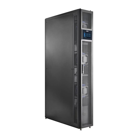
Components Identification Touch Panel Front Door Leveling Feet (Figure 2-5: Main External Components) InfraSuite R Series – Air Cooled Type... - Page 13 Indoor Unit Interior Evaporator Control Box Air Filter Power Box Inverter Compressor Condenser Sight Glass (Figure 2-6: Main Internal Components)
- Page 14 Outdoor Unit Electrical Box Power Input Liquid Pipe Signal Input Discharge Pipe (Figure 2-7: Outdoor Unit Components) InfraSuite R Series – Air Cooled Type...
-
Page 15: Chapter 3 : Installation
Chapter 3 : Installation WARNING: Only service personnel can perform the following installation procedures. No installation, piping or handling should be performed without authorization so as to avoid equipment damage and personal injuries. WARNING: The high voltage and high-pressure refrigerant in the equipment can be fatal! The inner components can potentially be dangerous, and only qualified service personnel can perform wiring and piping. -
Page 16: Clearance Zone
3.1.1 Clearance Zone Indoor unit A minimum of 900 mm (36”) of clear floor space in front of and behind the equipment is recommended for service access. All required normal maintenance is performed from the front and rear of the equipment. 47.2 in. - Page 17 Outdoor unit The outdoor unit will have a large amount of air flow that discharges heat into the atmosphere. Therefore, the outdoor unit should be installed in a clean area free of debris, away from dirt and foreign objects that may block the condenser. In addition, the outdoor unit must not be located near steam, hot air or flue gas outlets.
-
Page 18: Handling
3.1.2 Handling Before moving the equipment to the installation site, plan the route according to the following instructions: 1. Make sure the passage, floor, elevator or slope on the handling route can bear the weight of the equipment and handling device, and there is sufficient space to avoid collisions. 2. -
Page 19: Remove The Transport Fasteners From The Compressor
3.1.3 Remove the Transport Fasteners from the Compressor (Figure 3-3: Removing the Side Panel) If the side panel is locked, use a No. 2 Phillips screwdriver to remove the screws first. Hold the side panel with your hand when the screws are being removed in order to prevent the panel from falling. -
Page 20: Positioning
Cabinet fasteners If the adjacent cabinets are Delta cabinets (MSR1110 and MSR2110), you may use connecting fasteners to fix the equipment. Each cooling unit is provided with four connecting fasteners (two at the front and two at the rear). You must remove the front and back doors before installing the connecting fastener. - Page 21 Step 3 Use the key to unlock the rear door, remove the earth wire, raise the door, and take it out. The rear door is of the split type and, if necessary, take down both panels. NOTE: Put the front and rear doors that have been removed in a safe place so as to avoid any equipment damage or personal injury due to collisions.
- Page 22 L-shape mounting bracket The L-type balance support is originally used to fix the cooling unit on the pallet during transportation and can be used for ground fixing after positioning to provide extra locking force. 1. Use two M6 screws to fix the L-type balance support under the front door (with the extruding part forward) as shown in the figure.
- Page 23 Leveling feet After moving the unit into place, use a wrench to rotate clockwise the four levelers beside the casters to put them down and stabilize the unit on the floor. Make sure the unit cannot slide or topple. The leveling feet may be fastened or loosened with a No. 8 hex wrench.
-
Page 24: Outdoor Unit Installation
3.1.5 Outdoor Unit Installation Install the outdoor unit according to the following instructions. Open the wooden box and take out the Combine the No. 1 floor stand X2, No. 2. support outdoor unit accessory pack. X1, and No. 3 M6 screw X8 of the accessory pack into a floor stand set (attached at a torque of 45kgf/cm ). -
Page 25: Outdoor Side Cover Installation
NOTE: If you require a vertical installation, please contact Delta customer service. 3.1.6 Outdoor Side Cover Installation Follow the instructions below to install the side sealing plate of the outdoor unit. Take Cover-1 (see Figure 3-9) and install it to protect the coil pipe. - Page 26 NOTE: The recommended installation torque for M4 screws is 20 ± 2 kgf/cm Take Cover-2 and install it to where Figure 3-9-3 indicates. Please use 2 pieces of M4*L10 screws for the installation. Lock the screws at where Figure 3-9-4 indicates. (Figure 3-9-3: Install the Cover) (Figure 3-9-4: Lock the Screws) Take Cover-3 and install it at the circled place in Figure 3-9-5.
- Page 27 (Figure 3-9-6: Lock the Screws) (Figure 3-9-7: Lock Three Screws at the Bottom) Take 2 cable mounts and install them on where Figure indicates. (Figure 3-9-: Install the Cable Mount)
- Page 28 Take 4 pieces of cable ties to fix the NTC cables as shown in Figure 3-9-9. (Figure 3-9-9: Install the Cable Ties) Take Cover-4 and install it at the circled place in Figure 3-9-10. Please use 2 pieces of M4*L10 screws and lock them at where Figure 3-9-11 indicates. (Figure 3-9-10: Install the Cover) (Figure 3-9-11: Lock the Screws) InfraSuite R Series –...
-
Page 29: Installation Of Pipeline
Installation of Pipeline 3.2.1 Refrigerant Piping The top piping unwelded cap is inserted into the connecting copper pipe for welding. Top Piping Bottom piping and the connecting pipe of the external unit. Use a pipe cutter to cut and remove the outside of the copper pipe. -
Page 30: 3.2.1.1 Installation Of The Protection Cover For Piping
3.2.1.1 Installation of the Protection Cover for Piping 1. Take a snap bushing and install it on Cover-5 as shown in Figure 3-11. (Figure 3-11: Install the Snap Bushing) 2. Take Cover-5 and install it at where Figure 3-11-1 indicates. Please use 7 pieces M4*L10 screws for the installation. - Page 31 (Figure 3-12: Drain Pipe) Gravity drainage is completely driven by the drain pipe height and slope. Therefore, please follow and maintain the following principles. (1) Please maintain a direct descend of the drainage pipes to the raised floor, else condensed water will gather on the pipelines. (2) The water drainage slope of the drain pipes beneath the raised floor must be greater than 1/100 to ensure normal flow rate of the condensed water.
- Page 32 (4) If the U-trap cannot be installed correctly, please install a check valve on the drain pipes to prevent air or condensed water in drain pipes from returning to the equipment. (5) Do not install two U-traps because this will cause gas blockage. 8”...
-
Page 33: Opening Hole And Related Locations
3.2.3 Opening Hole and Related Locations Drill holes on the raised floor or ceiling according to the piping mode (top or bottom) as shown in the following figures for pipe passing. The top and the bottom pipelines must be enclosed when the unit is ready to be shipped. After the external pipeline is installed and put on the copper sheath found in the accessory pack, in order to avoid the copper pipe damage. -
Page 34: Connection Of Cables
Connection of Cables 3.3.1 Connecting the Power Cable (Use Accessory Pack Item: 3 Cable Gland) Prior to connection, you must make sure that the external power source is disconnected. Prior to connection, it is required to remove the cap from the power terminal of the indoor unit and make sure that the cable is fastened before the cap is put back on. - Page 35 Connecting indoor unit power wire (single power supply) Step 1 At the rear of the top/bottom of the indoor unit cabinet, use needle-nose pliers to remove the knocking-piece at the top/bottom of the cabinet; remove the cable gland from the accessory package and remove its nut.
- Page 36 Step 4 For the routing wire, use the cable tie to fasten it onto the cabinet’s supporting column. Step 5 Fasten the cable gland. Top Power Input Bottom Power Input (Figure 3-16: Signal Power Supply Wiring) InfraSuite R Series – Air Cooled Type...
- Page 37 Connecting the indoor unit’s power cable (dual power supply) Step 1 At the rear of the top/bottom of the indoor unit cabinet, use needle-nose pliers to remove the knocking-piece at the top/bottom of the cabinet; remove the cable gland from the accessory package and remove its nut.
- Page 38 Step 4 For the routing wire, use the cable tie to fasten it onto the cabinet’s supporting column. Step 5 Fasten the cable gland. An Example of Parts of an Earthing Terminal Top Power Input Bottom Power Input (Figure 3-18: Dual Power Supply Wiring) InfraSuite R Series –...
- Page 39 Connecting the outdoor unit’s power wire (Use accessory pack item: 4 cable glands) Cable size: 1. When using indoor unit power supply: Use cabling 16 AWG (1.3 mm ) or greater for power wires and control lines. 2. When using independent power supply: Use cabling 14 AWG (2 mm ) or greater for power wires and control lines.
- Page 40 Step 2 Pass the external wire and the signal cable through the cable connector to the indoor unit’s outdoor terminal L1/L2/L3 and fasten it. Step 3 Connect the PE line to the cabinet ground stud. Step 4 For the routing wire, use the cable tie to fasten it onto the cabinet’s supporting column. Step 5 To install the outdoor power wire, one must use the wire mount fix cable as shown in Figure 3-21.
-
Page 41: Connecting The Signal Cables
WIRE MOUNT (Figure 3-21: Outdoor Power Cable) 3.3.2 Connecting the Signal Cables Step 1 At the rear of the indoor unit’s cabinet top, lift the signal cover; or at the bottom rear, use needle-nose pliers to remove the knocking-piece. Remove the cable gland from the accessory pack and remove its nut. - Page 42 ❶ ❷ ❸ ❹ ❺ ❻ ❼ ❽ (Figure 3-22: Connecting the Signal Cables) Table 3-1: X1 & 2 Contact Description Name Function Description RS485+ ❶ Communication with external unit RS485- ❷ CAN+ ❸ Group communication CAN- ❹ RS485+ ❺ Communication with outdoor unit RS485- ❻ ...
- Page 43 Name Function Description 12VDC ❶ Sensor power ❷ Input dry contact + ❸ Fire, smoke warning Input dry contact - ❹ Input dry contact + ❺ Remote startup/shutdown Input dry contact - ❻ ❼ ❽ Table 3-2: X1 & 2 Function Description Item Description The RS485 port allows you to use the Modbus protocol to connect...
- Page 44 Communication with external unit wiring: (X1 Terminal Pin 1 & 2) DCMS (Datacenter Control and Management System) X1-1 X1-2 (Figure 3-23: Connect RS485) Group communication wiring: (X1 Terminal Pin 3 & 4) X1-3 X1-3 X1-4 X1-4 (Figure 3-24: Connect the Group Communication Line) InfraSuite R Series –...
- Page 45 Communication with outdoor unit: (X1 Terminal Pin 5 & 6) X1-5 X1-6 Outdoor Unit Indoor Unit (Figure 3-25: Communication Connection with the Outdoor Unit) Total alarm wiring: (X1 Terminal Pin 7 & 8) DCMS (Datacenter Control and Management System) X1-7 X1-8 (Figure 3-26: Connect the Alarm Output) Fire, smoke warning wring: (X2 Terminal Pin 3 &...
- Page 46 Remote startup/shutdown wring: (X2 Terminal Pin 5 & 6) X2-5 DCMS (Datacenter Control and Management System) X2-6 (Figure 3-28: Connect the Remote Switch Function) InfraSuite R Series – Air Cooled Type...
-
Page 47: Connecting The External Temperature And Humidity Sensor
3.3.3 Connecting the External Temperature and Humidity Sensor These sensors are used to detect the temperature and humidity of the hot/cold air corridors. Installation location is based on on-site conditions. It is suggested that sensors be placed in the hot air corridor where the heat source is accumulated, or in a cold air corridor where more cold air is needed. - Page 48 Step 2 Set up the dip switch for the temperature and humidity sensor. The sensor appears as in Figure 3-30. For the specific setup method, refer to Table 3-3 below. (Figure 3-30: Dip Switch Appearance) Table 3-3: Instructions for Operating the Temperature and Humidity Sensor Dip Switch Dip Switch Serial Number Detection Addressing...
-
Page 49: System Management
System Management For detailed information of system management, refer to the Installation Manual. The Manual contents are for reference only. 3.4.1 Charging Refrigeration Oil While the compressor is operating, the lubricant inside it will more or less be brought outside the compressor by the high pressure and high-speed refrigerant gas. -
Page 50: Vacuum Pumping
Table 3-4: Vacuum and Charging Refrigerant Tools Item Tool Manifold with gauges (R410A) Vacuum gauges Vacuum pump Refrigerant R410A NOTE: The vacuuming and filling of refrigerant must be carried out by Delta authorized personnel. InfraSuite R Series – Air Cooled Type... -
Page 51: Chapter 4 : Initial Startup
Chapter 4 : Initial Startup Pre-start Inspection WARNING: Only qualified service personnel can carry out the installation procedures in this chapter. WARNING: The high voltage and refrigerant in the equipment can cause personal injuries! Make sure the input power has been disconnected before the following actions. WARNING: ... -
Page 52: Power On
Electronic connection The rated value of the input power conforms to that marked on the nameplate. The equipment has been properly grounded. All electronic connections are tight and stable. The remote temperature (humidity) sensors have been correctly connected ... -
Page 53: Charging Refrigerant
For how to interpret the values shown on the main page and how to operate the main page, refer to Chapter 5. Operation. Charging Refrigerant Before powering on, the system needs to be filled with refrigerant since if the compressor runs in vacuum, it will be damaged. - Page 54 Table 4-1: Vacuum and Charging Tools Item Tool Manifold with gauges (R410A) Vacuum gauges Vacuum pump Refrigerant R410A NOTE: The vacuuming and filling of refrigerant must be carried out by personnel authorized by Delta. InfraSuite R Series – Air Cooled Type...
-
Page 55: Chapter 5 : Operation
Chapter 5 : Operation Main Page Once the system is connected to the power feed, the screens to be read appear one after another on the touch screen monitor. Loading screen: Once the screens to be read appear, the main page will automatically come up. -
Page 56: Account Authority And Login
Operation may only begin after login. Account Authority and Login Click on the “Log In” icon on the upper right corner of the status page to access the login page. There are three operator types: Operator Type Functions User Measurement (partial functions) Operator Measurement, Setup (partial functions);... - Page 57 If you want to re-enter the above menu, you must re-enter the password. NOTE: To avoid unauthorized change of and access to important settings, do not disclose the administrator password. To get the administrator’s password, contact Delta’s service personnel.
-
Page 58: How To Operate The Main Page
How to Operate the Main Page Item Description Click here for start-up/shutdown operations and for Main displaying the Main Page. Click here to inquire about the system status. Sub- Measurement menu: System Status, Data History Click here for Control Type, Controller Setting, Alarm Setting, Exceed Alarm Setting, Group Control Setting, and other functions. - Page 59 Item Description Shows the number of warnings that are currently Current Warnings active. If there are no warnings, on the other hand, this is the Historical Event Log. Shows whether the buzzer is currently operating or if it is muted. Buzzer Click here to turn on or to mute the buzzer.
-
Page 60: Startup
Startup 5.4.1 Operating Settings Path: Main Page → Setup → Set Point Setting Follow this path to set up: Type of temperature and humidity control (Supply Air/Return Air/Cold Aisle/Hot Aisle); temperature control area; humidity control area uses reasonable settings. InfraSuite R Series – Air Cooled Type... -
Page 61: Startup
5.4.2 Startup Path: Main Page → Main → Power Icon While in standby, once it is connected to the power feed for the first time, the compressor heater crank case will begin to warm up (for 12 hours). Do not start up or run the machine before the warm-up is finished. -
Page 62: Inquiry Of System Status
Inquiry of System Status 5.5.1 System Status Path: Main Page → Measurement → System Status Inquiry items available depend on logged-in operator type. InfraSuite R Series – Air Cooled Type... -
Page 63: Data History
5.5.2 Data History Path: Main Page → Measurement → Data History... -
Page 64: Warning
5.5.3 Warning Path: Main Page → Maintenance → Warning InfraSuite R Series – Air Cooled Type... -
Page 65: Historical Event
5.5.4 Historical Event Path: Main Page → Maintenance → Historical Event... -
Page 66: Run Hours
Event record: Click “Download” to download the event record to a portable flash drive. 5.5.5 Run Hours Path: Main Page → Maintenance → Run Hours InfraSuite R Series – Air Cooled Type... -
Page 67: Group Setting
5.5.6 Group Setting Path: Main Page → Setup → Group Control Setting 1. Group Mode OFFON (Enable group function) 2. Select how many cooling units in a group, and how many cooling units for backup (less than group number). 3. The time interval (h:m) for cooling units to shaft between operation modes (on or standby). -
Page 68: Summary Of Parameters Settings
Summary of Parameters Settings Parameter Setting Range Description Default Setting Note 5.6.1 Setup-->Set Point Setting Return Air It is Choose a control recommended Supply Air type that suits to use supply Control Type Supply Air the needs of the air temperature Cold Aisle computer room. - Page 69 Parameter Setting Range Description Default Setting Note The water Leak leakage alarm On/Off Shutdown may shut down the unit The first time a unit starts Compressor operating, the On/Off Preheating compressor needs preheating Enable the Heater heater function if On/Off Enable a unit includes a heater...
- Page 70 Parameter Setting Range Description Default Setting Note When using the Group Setting group Function, it is Rotation Time 0-999h:0-60m unit operating 0h:0m recommended rotation time to set to 24h:00m. 5.6.4 Setup-->Alarm Setting-->Sensor Supply Air When the sensor Sensor 1-2 On/Off signal is lost, the Abnormality alarm will go off...
- Page 71 Parameter Setting Range Description Default Setting Note When there is a Compressor compressor 1 Abnormality On/Off abnormality, the (Inverter) alarm will go off When there is an Outdoor Fan outdoor fan On/Off Abnormality abnormality, the alarm will go off When there is an On/Off abnormality, the Abnormal...
- Page 72 Parameter Setting Range Description Default Setting Note 5.6.7 Setup-->Exceed Alarm Setting-->Air Side On/Off Setting supply Supply Air air temperature Temp High 68-122°F high alarm value On/Off Setting supply Supply Air air temperature Temp Low 41-59°F low alarm value On/Off Setting return air Return Air temperature high Temp High...
- Page 73 Over High Suction If it needs to be Pressure On/Off Display or not changed, Over Low please contact Discharge Delta. Temp Over On/Off Display or not High Suction Temp On/Off Display or not Over Low 5.6.9 Setup-->General Settings Setting Date...
- Page 74 Parameter Setting Range Description Default Setting Note The LCD will shut down after LCD Energy this amount of 1-480min 1 min Saving Time time has passed without being used 20-100 Screen lightness Lightness When an alarm goes off, the Buzzer on/off buzzer will be on/off...
-
Page 75: Shutdown
Shutdown Path: Main Page → Main Screen → Power Icon When clicked again during operation, the unit will begin the shut-down procedure. When the shutdown procedure is performed, the indoor fan will continue to operate and will be turned off after a delay of several tens of seconds. -
Page 76: Chapter 6 : Troubleshooting
Chapter 6 : Troubleshooting WARNING: The following troubleshooting actions can only be carried out by qualified service personnel. Unauthorized actions may lead to major danger or equipment damage. Alarm Alarm Name Possible Cause Corrective Action Severity 1. The ambient humidity is 1. - Page 77 Alarm Alarm Name Possible Cause Corrective Action Severity 1. Poor refrigerant system 1. Refrigerant system processing processing 2. Outdoor fan abnormality 2. Check the fan wiring or replace the fan 3. Outdoor VFD Discharge Temp abnormality 3. Check the VFD Over High 4.
- Page 78 Alarm Alarm Name Possible Cause Corrective Action Severity 1. Fan wiring is loose 1. Check the fan wiring 2. The blade is stuck due to 2. Remove foreign objects foreign matter and confirm that the Fan CH4 blades are not damaged 3.
- Page 79 Alarm Alarm Name Possible Cause Corrective Action Severity 1. The temperature of the 1. Check the surrounding outdoor unit environment environment is too high 2. Check the fan wiring or 2. Outdoor fan abnormality replace the fan 3. Poor refrigerant system 3.
- Page 80 Alarm Alarm Name Possible Cause Corrective Action Severity 1. Poor VFD heat 1. Check the surrounding dissipation heat dissipation Inverter Over environment Temp 2. Contact the service personnel 1. VFD voltage abnormality 1. Check the VFD input power Inverter Voltage Abnormality 2.
- Page 81 Alarm Alarm Name Possible Cause Corrective Action Severity 1. Indoor and outdoor 1. Check the connection of communication lines are indoor and outdoor Outdoor Unit disconnected communication lines Comm Abnormality 2. Outdoor unit power 2. Check the input power of supply abnormality the outdoor unit 1.
- Page 82 Alarm Alarm Name Possible Cause Corrective Action Severity 1. Insufficient refrigerant 1. Replenish the amount of refrigerant after 2. Indoor fan abnormality maintenance of leakage 3. Indoor side load is too point 2. Check the fan wiring or 4. The temperature of the replace the fan outdoor unit environment 3.
- Page 83 Troubleshooting Item Sign of Failure Possible Cause Instructions 1. Input power is 1. Check the input power disconnected and circuit breaker The air conditioner 2. The air conditioner is 2. Turn on the air conditioner does not start not turned on 3.
- Page 84 Troubleshooting Item Sign of Failure Possible Cause Instructions 1. The air conditioner is 1. Turn on the air conditioner not turned on 2. Turn on the outdoor unit 2. The outdoor unit panel panel circuit breaker circuit breaker is not 3.
-
Page 85: Appendix 1 : Technical Specifications
Appendix 1 : Technical Specifications Model RWD030-B8 Maximum cooling capacity 30kW Input voltage 3- 200-208 VAC +G 50/60 Hz Maximum current Air volume 2945CFM Type refrigerant R410A Filter Merv.1 Refrigerant discharge pipe 5/8" Refrigerant pipe Refrigerant liquid 1/2" Size (Width x Height x Depth) 11.8 x 78.7 x 42.9"... -
Page 86: Appendix 2 : Warranty
Appendix 2 : Warranty The Seller warrants this product, if used in accordance with all applicable instructions, to be free from original defects in material and workmanship within the warranty period. If the product has any failure problem within the warranty period, the Seller will repair or replace the product at its sole discretion according to the failure situation. -
Page 87: Appendix 3 : Maintenance
Appendix 3 : Maintenance Quarterly Maintenance Date: Model: Clean Clean the following components and use an air gun if necessary. Filters (replace them if necessary) Completed Replaced Front and rear doors Completed Condensed water pan Completed Condensed water pipe Completed Be sure to disconnect and lock the input power before cleaning the following components. - Page 91 - Regional Office The United States Australia Delta Electronics (Americas) Ltd. Delta Energy Systems Australia Pty Ltd. 46101 Fremont Blvd. Fremont, CA 94538 Unit 20-21, 45 Normanby Road, Notting Hill VIC 3168, Australia T +1 510 344 2157 T +61 3 9543 3720 E ups.na@deltaww.com...
- Page 92 5013295900...
Need help?
Do you have a question about the InfraSuite RWD030R and is the answer not in the manual?
Questions and answers