Table of Contents
Advertisement
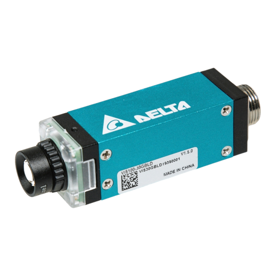
VIS100 Operating Manual
1.1 Packaging and Optional Parts .......................................................................................... 1-1
1.2 Sensor Unit ......................................................................................................................... 1-2
1.2.1 Specifications ............................................................................................................. 1-2
1.3 Camera and Lens Selections ............................................................................................ 1-3
2.1 Input/Output (I/O) Terminal Block ..................................................................................... 2-1
2.2 Grounding and Installation ................................................................................................ 2-2
2.2.1 Grounding .................................................................................................................. 2-2
2.2.1 Installation ................................................................................................................. 2-2
3.1 Application Names and Functions ..................................................................................... 3-1
3.2 GUI ....................................................................................................................................... 3-3
3.2.1 Main Page ................................................................................................................. 3-4
3.3.2 Menu Page .................................................................................................................. 3-5
3.3.3 Language ................................................................................................................... 3-8
3.3.4 Information Page ......................................................................................................... 3-9
3.3.5 Statistics Page ............................................................................................................. 3-9
4.1 Getting Start ......................................................................................................................... 4-1
4.1.1 Camera Default IP Address ....................................................................................... 4-1
4.1.2 Open the Application ................................................................................................... 4-1
4.1.3 Log in to the Application ............................................................................................ 4-2
4.1.4 Basic Operation ........................................................................................................... 4-2
4.2 Configuration ....................................................................................................................... 4-3
4.2.1 Camera ...................................................................................................................... 4-3
4.2.2 Communication ........................................................................................................... 4-4
4.2.3 Account ..................................................................................................................... 4-6
4.2.4 Mode ......................................................................................................................... 4-7
4.2.5 Camera IP ................................................................................................................. 4-8
4.2.6 Export/Import Settings ............................................................................................... 4-8
Table of Contents
V1.0
i
Advertisement
Table of Contents

Related Manuals for Delta VIS100-30G12D


Summary of Contents for Delta VIS100-30G12D
-
Page 1: Table Of Contents
VIS100 Operating Manual V1.0 Table of Contents Chapter 1: Components and Specifications 1.1 Packaging and Optional Parts ..................1-1 1.2 Sensor Unit ......................... 1-2 1.2.1 Specifications ......................1-2 1.3 Camera and Lens Selections .................... 1-3 Chapter 2: Input and Output Interface 2.1 Input/Output (I/O) Terminal Block .................. - Page 2 Chapter 5: Inspection tools 5.1 Region of Interest (ROI) ..................... 5-1 5.2 Filters ........................... 5-2 5.3 Barcode ..........................5-3 5.3.1 1D Barcode ........................ 5-3 5.3.2 Data Matrix Code (DMC) ..................... 5-4 5.3.3 QR Code ........................5-6 5.3.4 Micro QR Code ......................5-7 5.4 Blob ............................
- Page 3 Foreword Thank you for your purchase of the high performance Delta Vision Sensor VIS100 from Delta Electronics Inc. This operating manual covers the component description, installation, operation, troubleshooting, peripherals, and maintenance. To guarantee proper installation and operation of the system, please carefully read this operating manual and safe keep it for future reference.
-
Page 4: Chapter 1: Components And Specifications
2) Lens (optional, first set is included with the 8mm lens) 1.1.1 Unit Packaging The following is included: 1) 0.3M (640 x 480 pixels) Vision sensor: VIS100-30G12D / VIS100-30GBLD 2) 0.4 m TCP/IP cable: VIS-CA04S VIS100 Vision Sensor Operating Manual... -
Page 5: Sensor Unit
Chapter 1 Components and Specifications 1.2 Sensor Unit 1.2.1 Specifications General Specifications Input power DC 9~30 Voltage Operation voltage 90%~110% of rated voltage Power consumption Less than 0.2A Ingress Protection Rating IP55 Operating temperature -20°C ~+5°C Functional Specifications Type Mono 0.3M pixel: 640(Horizontal) * 480(Vertical),90fps... -
Page 6: Camera And Lens Selections
1 章 部件名稱及規格 1.3 Camera and Lens VIS100 Sensor includes 0.3M pixel CMOS sensor, lens is the 8mm (M12, C mount) specification. Before selecting the lens, please confirm the field of view and working distance between the lens and test object. - Page 7 Chapter 1 Components and Specifications Focal Focal Focal Focal Focal Focal Resolution Field of view length length length length length length um/pixel (mm) 12mm 16mm 25mm 35mm 50mm Horizontal 1024 (H)*Vertical (V) Dis. Dis. Dis. Dis. Dis. Dis. * 480 * 768 27.5(H)*20.6(V) 43.0...
-
Page 8: Chapter 2: Input And Output Interface
Chapter 2 Input and Output Interface Chapter 2 Input and Output Interface VIS100 input and output interfaces include the following: Ethernet The pins and wiring connections are defined and detailed below. 2.1 Input / Output (I/O) Terminal Block Wiring the Sensor: Connect and secure the I/O Cable to the I/O Cable connector located on the bottom of the Vision Sensor. -
Page 9: Grounding And Installation
Chapter 2 Input and Output Interface Input circuit diagram Output circuit diagram 2.2 Grounding and Installation 2.2.1 Grounding Precautions Do not connect or disconnect the wires while system is powered on. The grounding wire should be at minimum length using the regulated wire gauge. The grounding resistance must be under 100Ω. -
Page 10: Chapter 3: Basic Operation
Chapter 3 Basic Operation Chapter 3 Basic Operation 3.1 Application Names and Functions You can remotely setup and configure your 1D/2D reader or Absence/Presence Checker on your PC or mobile device via Wi-Fi using the web browser. This allows you to see the inspection process in real-times and adjust the parameters anywhere in your factory. - Page 11 Chapter 3 Basic Operation Inspection Tools Icon Name Inspection Tool Filter Filter Tool. Uses one or more filters to process the image for better (*1)(*2) results. Barcode Barcode reader tool for reading barcodes. (*1)(*3) Data Matrix Data Matrix code reader tool for reading data matrix codes. (*1)(*4) QR Code QR code reader tool for reading QR codes.
-
Page 12: Gui
Chapter 3 Basic Operation (*1) You must log in to operate. (*2) You need a license for this function. (*3) You need a Complete license or 1D license or 1D/2D license for this function. (*4) You need a Complete license or 2D license or 1D/2D license for this function. (*5) You need a Complete license or Absence/presence license for this function. -
Page 13: Main Page
1000 px and 1300 px shows the Menu on the left side. Window width larger than 1300 px shows the Menu on the left and Statistics on the right of the window. 3.2.1 Main Page The information showing under the “Delta” logo in the Main Page Name : Name of the camera (set in Camera Setting) ... -
Page 14: Menu Page
Chapter 3 Basic Operation 3.2.2 Menu Page After you log in with username and password, the menu or menu button will show on. The menu is on the left side of the screen when the browser is in full screen width The menu contains inspection tools that you can use in the process according to your license. - Page 15 Chapter 3 Basic Operation The Configuration page contains all the camera settings. PC menu (Application) Smartphone To access the menu, tap the top left button (left figure) on the screen, and the menu (right figure) wikk be shown. VIS100 Vision Sensor Operating Manual...
- Page 16 Chapter 3 Basic Operation The Application menu contains the inspection tools that you can use to process an image according to your license. To activate an application, select the check box next to the tool (check barcode as shown). The Configuration page contains all the camera settings. VIS100 Vision Sensor Operating Manual...
-
Page 17: Language
Chapter 3 Basic Operation 3.2.3 Language The application supports four languages: Simplified Chinese, English, Japanese, Korean. PC: You change the language by clicking the Language button at the top left of the menu page Smartphone: You can change the language by tapping the Language button in the Main page. VIS100 Vision Sensor Operating Manual... -
Page 18: Information Page
Chapter 3 Basic Operation 3.2.4 Information Page The Information page contains the following basic information. Version: Application version. ID: Camera identification number. License: Application license type. Date: Manufacture date (DD/MM/YYYY format). 3.2.5 Statistics Page The Statistics page contains the following information. Total Triggered: Total number of times the camera is triggered. -
Page 19: Chapter 4: Inspection Setting Process
Chapter 4 Inspection Setting Process Chapter 4 Inspection Setting Process 4.1 Getting Start 4.1.1 Camera Default IP Address The following table lists the default camera IP address (for camera from Inspiraz Technology). Name Address 192.168.1.10 Mask 255.255.255.0 Gateway 192.168.1.1 192.168.1.1 4.1.2 Open the Application You must use a web browser to open this application. -
Page 20: Log In To The Application
Chapter 4 Inspection Setting Process 4.1.3 Log in to the Application You must log in to change the camera settings. Open the application on your Smartphone’s or PC’s web browser. Click to open the login page. Enter the Username and Password. Click Login. -
Page 21: Configuration
Chapter 4 Inspection Setting Process Apply changed settings • Start: Click to stop all inspections, then click either (run once) or (run) to view the result with the changed settings. 4.2 Configuration 4.2.1 Camera Boot Autorun Uses the current saved settings to run the camera after rebooting. ... -
Page 22: Communication
Chapter 4 Inspection Setting Process Trigger: Sets the camera trigger, communication trigger will descript in 4.2.2. Hardware: Shows the trigger timeout, delay and signal edge. Continuous: Sets the cycle time for continuous internal trigger. Light: Sets the camera light (depends on the camera model). 4.2.2 Communication There are three types of communication. - Page 23 Chapter 4 Inspection Setting Process Comm. Setting • Disable : Disable communication over the network. • UDP: Use the UDP client to the send result data .(no error checking) IP: Destination UDP server IP address. Port: Destination UDP server port number. Send header: Send special header (for example<barcode>) before sending the result Header (ASCII): Setting the Header word.
-
Page 24: Account
Chapter 4 Inspection Setting Process 4.2.3 Account User: Select Add User to add a new user. • Username: Enter the new username. • Password: Enter the new user password. • Confirm Password: Enter the password again to confirm. Delete User: Select Delete User to delete a user. -
Page 25: Mode
Chapter 4 Inspection Setting Process Change Password: Select Change Password to change the current user password. • Password: Enter the new user password for the current user. • Confirm Password: Enter the password again to confirm. 4.2.4 Mode The VIS100 application can operate in either Code Reader or Blob mode. Use Mode Selection to switch between the 2d code reader and the blob detector function according to your license. -
Page 26: Camera Ip
Chapter 4 Inspection Setting Process 4.2.5 Camera IP Enter the camera’s IP address, mask address, gateway address and DNS address. • IP: Camera IP address • MASK: Subnet mask address • Gateway: Default gateway address • DNS: Dynamic name server address •... -
Page 27: Chapter 5: Inspection Tools
Chapter 5 Inspection Tools Chapter 5 Inspection tools 5.1 Region of Interest (ROI) You can set one ROI in every inspection tool (such as Barcode) to optimize tool performance. Each inspection tool has 3 types of ROIs Complete: Uses the whole image for the process. Rectangle: Defines a rectangle ROI that you can rotate and resize Drag to rotate the ROI... -
Page 28: Filters
Chapter 5 Inspection Tools 5.2 Filters You can use up to five different filter combinations in a single ROI, and there are fifteen different filter types. Gauss: Smoothes the image using the discrete Gaussian function. The smoothing effect increases with increasing filter size. -
Page 29: Barcode
Chapter 5 Inspection Tools 5.3 Barcode Note that you must set the Mode selection to Code Reader mode. The VIS100 application can operate in either Code Reader or Blob mode. Please refer to Section 4.2.4 for the details of the Mode Settings. 5.3.1 1D Barcode Use the Barcode function to read and decode barcodes. -
Page 30: Data Matrix Code (Dmc)
Chapter 5 Inspection Tools Code Length: Select this check box to check the length of the decoded barcode. The result is OK if the code length matches, NG if the code length does not match. Code Content: Select this check box to compare the decoded barcode with a defined reference. For multiple code content, add a “,”... - Page 31 Chapter 5 Inspection Tools Timeout (ms) Defines the timeout on this function to ignore the current decoding process and continue with the remaining commands in the inspection process. Code Length: Select this check box to check the length of the decoded barcode. The result is OK if the code length matches, NG if the code length does not match.
-
Page 32: Qr Code
Chapter 5 Inspection Tools 5.3.3 QR Code Use the QR Code function to read and decode 2D QR codes. You can improve the reading speed by reducing the search area (using an ROI) and through other settings. Number of code: Defines the maximum number of codes available in the image. ... -
Page 33: Micro Qr Code
Chapter 5 Inspection Tools Standard: Fastest for finding codes Enhanced: More accurate in finding codes but slower than Standard Recognition mode Mode Maximum: Most accurate in finding codes but slowest compared to other modes Mirror Type Defines if the codes might be mirrored Expert Polarity Type Defines the polarity of the codes in the image... - Page 34 Chapter 5 Inspection Tools Code Length: Select this check box to check the length of the decoded barcode. The result is OK if the code length matches, NG if the code length does not match. Code Quality: Select this check box to check the quality of the decoded barcode. The result is OK if the code quality matches the selected standard, NG if the code quality does not match the standard.
-
Page 35: Blob
Chapter 5 Inspection Tools 5.4 Blob Note that you must set the Mode selection to Blob mode. The VIS100 application can operate in either Code Reader or Blob mode. Please refer to Section 4.2.4 for the details of the Mode Settings. You can use the Blob function when the image contains various regions of brightness that are clearly separated from each other. - Page 36 Chapter 5 Inspection Tools Ignore Boundary Objects: Select the check box to ignore detected objects that are in direct contact with the boundary of the search region. • Area Filter: Select the check box to define the minimum and maximum area size of detected objects.
-
Page 37: Chapter 6: Troubleshooting
Chapter 6 Troubleshooting Chapter 6 Troubleshooting 6.1 Troubleshooting Steps If there is no response after you enter the username and password on Login page. Try the following actions to resolve the problem. Reboot the camera. Delete the web browser cache and cookies. ...
Need help?
Do you have a question about the VIS100-30G12D and is the answer not in the manual?
Questions and answers