
Related Manuals for TESTO 0699 6446 Series


Summary of Contents for TESTO 0699 6446 Series
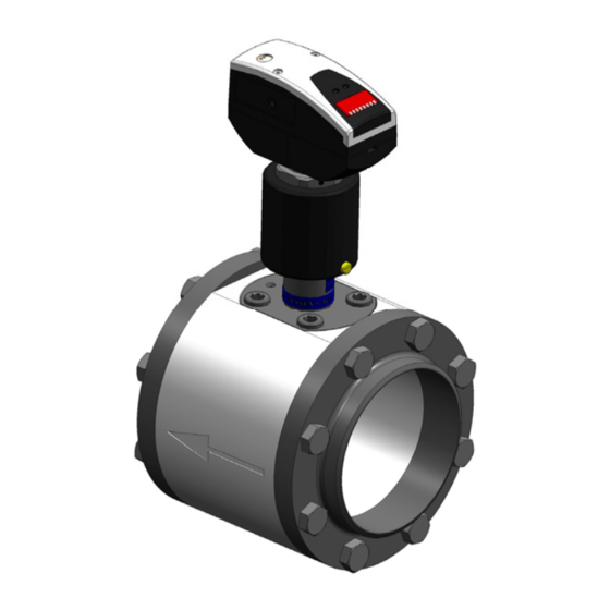
- Page 1 Compressed air counter Instruction manual 0699 6446/xx Standard 0699 6447/xx With probe removal under pressure...
-
Page 3: Table Of Contents
Contents Contents Page Introduction Notes on the instruction manual Receiving inspection, transport, storage Scope of delivery Warranty Description of the instrument Task and areas of application Technical data 3.2.1 Measuring block 3.2.2 Thermal mass flow sensor Accessories 3.3.1 Sealing cap (0699 6446/41) 3.3.2 Connecting cable with electrical isolator (0699 6446/42) 3.3.3... -
Page 4: Introduction
1 Introduction Introduction Notes on the instruction manual This instruction manual offers you, the user of the compressed air counter, 0699 6446 / 0699 6447 support during the installation, operation and main- tenance. Characters and symbols The following characters and symbols are used in this instruction manual to emphasize text passages that need special attention. -
Page 5: Receiving Inspection, Transport, Storage
1 Introduction Receiving inspection, transport, storage • Take note of undamaged packaging! Communicate damages to the packaging to your supplier. Retain the damaged packaging until the matter is settled. • Take note of undamaged contents! Communicate damages to the contents to your supplier. Retain the damaged goods until the matter is settled. -
Page 6: Scope Of Delivery
1 Introduction Scope of delivery Check the scope of delivery using the following table. The designations of the individual components can also be found in the following exploded view. The items 1, 3, and 4, marked in bold, are assembled and are to be checked. - Page 7 1 Introduction 0699 6446 Standard (3.10) + (3.20) (1.20) (1.30) (1.50) (1.40) (1.11) (1.12) (1.12) (1.10)
- Page 8 1 Introduction 0699 6447 With probe removal under pressure (3.10) + (3.20) (1.30) (1.50) (1.40) (1.11) (1.12) (1.12) (1.10)
-
Page 9: Warranty
2 Warranty Warranty The instruments are built in compliance with the applicable regulations and have left the factory in a properly-functioning state. However, if our product should give you reason for complaint, we will rectify deficiencies caused by errors in the factory free of charge. This is conditional upon an immediate report of these deficiencies within our granted warranty period. -
Page 10: Description Of The Instrument
3 Description of the instrument Description of the instrument Task and areas of application Measuring block with Compac welding neck flange The measuring block with Compac welding neck flanges enables the me- chanical and position-accurate fixture of the electronic mass flow sensor. The measuring block is welded into the pipelines with the Compac welding neck flanges. - Page 11 3 Description of the instrument • The display °C (LED4) cannot be selected. Signal output 1 • Switch signal is the limit value for volume flow, hysteresis or window function as NO or NC contact • Pulse sequence for consumption quantity with 1 pulse/standard litre (pulse length 2 ms) and 1 pulse/Nm³...
-
Page 12: Technical Data
3 Description of the instrument Technical data 3.2.1 Measuring block 0699 6446 Standard Material SVZ = Galvanized steel, 0699 6446/0x EST = Stainless steel, 0699 6446/1x Dimensions Quantity: Screws N Ø screw holes SL Ø D2 DN (see table) Part no. Nominal width (mm) - Page 13 3 Description of the instrument 0699 6447 With probe removal under pressure Material SVZ = Galvanized steel, 0699 6447/0x EST = Stainless steel, or 0699 6447/1x Dimensions 0699 6447 Quantity: Screws N Ø screw holes SL Ø D2 DN (see table) Part no.
-
Page 14: Thermal Mass Flow Sensor
3 Description of the instrument 3.2.2 Thermal mass flow sensor The thermal mass flow sensor for the compressed air volume flow meas- urement is independent of the process pressure and the media temperature. The electronic sensor assembly is adjusted to the data of the measurement block (diameter/medium). - Page 15 3 Description of the instrument Dimensions 0699 6446 Standard Section A-A WAF 36 Direction of flow Item 1 Sensor display Item 2 Sensor probe component Item 3 Threaded pin Item 4 O-ring Item 5 Cylindrical pin for alignment in the direction of the flow Sensor weight 428 g...
- Page 16 3 Description of the instrument Dimensions 0699 6447 With probe removal under pressure Section A-A Direction of flow Item 1 Head of the electronic sensor assembly Item 2 Extension Item 3 Threaded pin Item 4 O-ring Item 5 Cylindrical pin for alignment in the direction of the flow Item 6 Sensor Electronic sensor assembly...
-
Page 17: Accessories
3 Description of the instrument Accessories 3.3.1 Sealing cap (0699 6446/41) Only for 0699 6446 Standard version. The sealing cap with internal thread is used for operating the pipeline without the mass flow sensor. Sealing mounted measuring block. 3.3.2 Connecting cable with electrical isola- tor (0699 6446/42) Uniform for all versions. -
Page 18: Additional Iso Calibration Points (0699 6447/22)
3 Description of the instrument 3.3.4 Additional ISO calibration points (0699 6447/22) Uniform for all versions. Other measurement points are calibrated for the ISO basic calibration. You must specify the number of required additional calibration points when order- ing. 3.3.5 DAkkS calibration (0699 6447/23) Uniform for all versions. -
Page 19: Security Measures
4 Security measures Security measures Intended purpose The compressed air counter is intended exclusively for use in pipe systems for working compressed air, provided that the calibration certificate does not explicitly allow using for other gases. Thanks to the design, operation in systems that are under pressure up to PN16 is possible. -
Page 20: Assembly, Commissioning And Operation
4 Installation Assembly, commissioning and operation The compressed air counter was reliably built and checked according to state-of-the-art technology and left the factory in a properly secure state. As the user, you are responsible for the compliance with all valid safety regulations, including: •... -
Page 21: Installation
5 Installation Installation ® Description of PBCOmpac flange The groove designed for holding the sealing element (O-ring) is dimensioned in such a way that the erection bolts can be tightened to the point of full- surface contact with the contact areas. ®... -
Page 22: Welded Connection To Pipeline With Pbcompac Flange
5 Installation Welded connection to pipeline with ® PBCOmpac flange To avoid a dissimilar metal weld when welding to the pipeline, the material of the flange must be steel or stainless steel, according to the pipeline. ® COMPAC flanges must be welded without warping so that the tightness achieved after assembly is optimal. -
Page 23: Installation Position
5 Installation 5.3.1 Installation position Do not install the electronic sensor assembly in the crossed-out installation positions shown in the following graphic. In the event of a limited flow, the specified accuracy cannot be maintained. The arrow shows the direction of flow for the medium. 5.3.2 Required measurement route Bear in mind the required inflow and outflow routes in order to achieve the... -
Page 24: Direction Of Flow
5 Installation 5.3.3 Direction of flow The direction of flow must be taken into account when installing the measur- ing block This is shown on the measuring block by means of an arrow. The arrow points in the direction in which the medium in the pipeline flows. 0699 6446 0699 6447 ®... - Page 25 5 Installation Alignment pins for hood (2-part) Hood (2-part) Pulling direction for remov- ing the hood parts Protection cap for transporta- tion for sensor tip • Remove the two-piece hood from the sensor. • Remove the protection cap for transportation from the sensor element. •...
-
Page 26: Installation Of The Electronic Sensor Assembly In The Interchangeable Fitting (Version 0699 6447)
5 Installation Installation of the electronic sensor assembly in the interchangeable fitting (version 0699 6447) Check tightness of the 4 screws that fasten the inter- changeable fitting • Check the 4 screws that connect the interchangeable fitting to the measuring block for a solid seating using an 8 mm Allen key. Alignment pins for hood (2- part) Hood (2-part) -
Page 27: Electrical Connection
5 Installation sensor assembly can only be inserted in its correct position in the interchangeable fitting. The display of the electronic sensor assembly points in direction from which the flow in the pipe comes. • Check the correct seating of the electronic sensor assembly. It must engage in place in such a way that it cannot turn. -
Page 28: 5-Wire Pin Assignment (Accessory)
5 Installation 5.6.1.1 1 x switch output, 1 x analog output (condition at delivery) The OUT1 output is used as a PNP signal output (switch signal) and the OUT2 output is used as an analog output. This is the configuration in which the electronic sensor assembly is delivered. -
Page 29: Operation
6 Operation Operation Removal of the electronic sensor assembly under pressure (only 0699 6447) The removal of the electronic sensor assembly while the interchangeable fit- ting is in the OPEN position, meaning turned into the pipe, can be extremely dangerous. The interchangeable fitting is to operated only by hand, not using tools. -
Page 30: Remove Electronic Sensor Assembly (Close)
6 Operation 6.1.2 Remove electronic sensor assembly (CLOSE) • Slowly and evenly turn the interchangeable fitting out of the pipeline only by hand, without tools, (to the left) in the direction of the arrow CLOSE. • Only when the interchangeable fitting is completely in the CLOSE position does the O-ring seal off the electronic sensor assembly from the pressurized line. -
Page 31: Types Of Operation
6 Operation Type Description 4 x LED, green Illuminated LED = display unit set LED1 = volumetric flow rate [Nm³/min (Nl/min)] LED2 = volumetric flow rate [Nm³/h (Nm³/h * 1000)]] LED3 = quantity counter [Nm³] LED4 blinking = quantity counter before last reset ... -
Page 32: Programming
6 Operation 6.2.2.3 Programming mode Setting the parameter values The instrument is switched to programming mode if a parameter is selected and the Set button is pressed for longer than 5 s (the parameter value is displayed flashing, then continuously increased). Here too, the instrument remains operational. -
Page 33: Adjustable Parameters
6 Operation 6.2.4 Adjustable parameters Switch point 1/2 Upper limit value at which the output changes its switch status. SP 2 is only active if OU2 = Hno, Hnc, Fno or Fnc (see below) Return switch point 1/2 Lower limit value at which the output changes its switch status. - Page 34 6 Operation Pulse setting 2 settings can be selected: • nL = 1 pulse per standard litre (pulse length: 2 ms) • nm³ = 1 pulse per Nm³ (pulse length: 100 ms) ImPS is only active if OU1 = ImP or OU2 = ImP Extended functions This menu point contains a submenu with further pa- rameters.
- Page 35 6 Operation Display unit 3 settings can be selected: • Lmin = Flow in Nl/min or Nm³/min • nm3h = Flow in Nm³/h or Nm³/h x 1000 • nm3 = Quantity counter in standard cubic metres Set the display unit before you set the values for the SPx, rPx, ASP and AEP parameters.
-
Page 36: Error Messages
6 Operation 6.2.4.1 Scaling the measuring range • With the parameter analog starting point (ASP), you determine at which measurement value the output signal is 4 mA. • With the parameter analog end point (AEP), you determine at which measurement value the output signal is 20 mA. •... -
Page 37: Menu Overview
6 Operation 6.2.6 Menu overview In the menu overview, (S) stands for the Set button and (M) for the Mode button on the electronic sensor assembly. (Nm³)* = Volume flow amount before the last reset. -
Page 38: Changing The Electronic Sensor Assembly (Version 0699 6446)
6 Operation Changing the electronic sensor as- sembly (version 0699 6446) The removal of the mounted electronic sensor assembly may be necessary for maintenance, cleaning and calibration purposes. Make sure that the pipeline is ventilated. Removing the sensor from a line that has not been depressurized can be extremely dangerous. -
Page 39: Cleaning The Sensor
24 months. This is mandatory for accounting purposes, please contact Testo. 0699 6477: Thanks to the interchangeable fitting, the calibration and service tasks for the electronic sensor assembly are also possible at any time with- out interruption of operation. -
Page 40: Troubleshooting
Please refer questions regarding the product, accessories or spare parts to our support team (German /English speaking): Telephone: +49 (7653) 681-650 email: applicationsupport@testo.de Exchange of damaged parts Damages to the compressed air counter that impact the pressure security may only be remedied by authorized personnel. - Page 41 Notes...
- Page 42 Notes...
- Page 43 Notes...
- Page 44 AG Postfach 1140, D-79849 Lenzkirch Testo-Strasse 1, D-79853 Lenzkirch GERMANY Phone: +49 (0) 7653 681-0 Fax: +49 (0) 7653 681-100 Internet: www.testo.com email : info@testo.com 0971.6446 02 en...
Need help?
Do you have a question about the 0699 6446 Series and is the answer not in the manual?
Questions and answers