Table of Contents
Advertisement
Quick Links
Advertisement
Table of Contents

Subscribe to Our Youtube Channel
Related Manuals for R.V.R. Elettronica BROADCAST EQUIPMENT HC08CH-FM


Summary of Contents for R.V.R. Elettronica BROADCAST EQUIPMENT HC08CH-FM
- Page 1 HC08CH-FM HC08CH-FM USER MANUAL VOLUME1 Manufactured by R.V.R ELETTRONICA Italia...
- Page 2 Declaration of Conformity Hereby, R.V.R. Elettronica, declares that this FM transmitter is in complian- ce with the essential requirements and other relevant provisions of Directive 2014/53/EU.
- Page 3 HC08CH-FM ELETTRONICA Technical Specifications HC08CH-FM Parameters U.M. Value Notes GENERALS Frequency range 87.5 ÷ 108 Rated output power Unbalaced Power Limit Ambient working temperature °C -5 to + 50 Ambient Working Humidity 85 (Without condensing) INPUTS Connector Impedance Power Coupler Number of Way Power Insertion Loss...
-
Page 4: Table Of Contents
HC08CH-FM ELETTRONICA Table of Contents 1. Preliminary Instructions 2. Warranty 3. First aid 3.1 Treatment of electric shocks 3.2 Treatment of electrical burns 4. General description 4.1 Unpacking 4.2 Features 4.3 Description of the Front Panel 4.4 Description of the Rear Panel 5. -
Page 5: Preliminary Instructions
The product should not be incorporated into a rack unless retailers. it is provided with adequate ventilation or the manufacturer's if your retailer cannot help you, contact R.V.R. Elettronica instructions have been followed. and describe the issue; if the staff deems it necessary, the authorization to send the equipment will be sent to you with the appropriate instructions;... -
Page 6: First Aid
• Call a doctor as soon as possible. R.V.R. Elettronica 3.1.2 If the victim is conscious Via del Fonditore, 2/2c 40138 BOLOGNA ITALY •... -
Page 7: General Description
ELETTRONICA 4. Descrizione Generale The HC08CH-FM, manufactured by R.V.R. Elettronica, is a hybrid coupler made with new concept technology. Its function is to take the RF signal coming from a maximum of eight external sources and combine its outputs to a single antenna output (or two outputs if the option is present) or to slotted cables. -
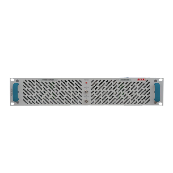
Page 8: Description Of The Front Panel
HC08CH-FM ELETTRONICA 4.3 Description of the Front Panel Figure 4.1 [1] RF MONITOR 1 BNC connector for RF monitor 1 output before the pass band filter. The output level is -60dB referred to the power output in 87.5 - 108 MHz range. [2] POWER Red LED, turns on when amplifier is switched on. [3] RF MONITOR 2 BNC connector for RF monitor 1 output after the pass band filter. The output level is -60dB referred to the power output in 87.5 - 108 MHz range. -
Page 9: Description Of The Rear Panel
HC08CH-FM ELETTRONICA 4.4 Description of the Rear Panel Figure 4.2 [1] INTERLOCK 1 BNC connector 1 to disable an external device, such as an exciter. In case of faults, the central conductor is grounded. [2] INTERLOCK 2 BNC connector 2 to disable an external device, such as an exciter. In case of faults, the central conductor is grounded. -
Page 10: Installation And Configuration Procedure
HC08CH-FM ELETTRONICA 5. Installation and Configuration Procedure Instructions are given in this chapter on installation and configuration of the equipment. Carefully perform all the steps described in this chapter both upon initial start-up and every time the main configuration is changed, for example when moving to a new transmission station or when replacing the equipment. IMPORTANT: always disconnect the mains power before carrying out any type of installation and/or maintenance. -
Page 11: Installation
HC08CH-FM ELETTRONICA 5.1 Installation 5.1.1 General Requirements The ventilation of the equipment and workplace must be suitable for maintenance according to the directive in force in the country in which this equipment is installed. To ensure correct operation of the appliance, there must be a clearance of at least 50 cm at the front and back of the device to facilitate the circulation of air through the ventilation grids. - Page 12 HC08CH-FM ELETTRONICA HC08CH-FM @ 230 Vac Main fuse (1x) F 3.15A type 5x20 Table 5.1: Fuses 5.1.3 Placement of the device Useful tips for correct installation: • Avoid the presence of external elements near the ventilation inlets and outlets, as they could prevent proper ventilation of the device. • Avoid proximity to a source of heat or flammable gas.
- Page 13 HC08CH-FM ELETTRONICA The station normally has an air outlet at the rear of the equipment: in which case, ensure adequate ventilation of the room. COLD 50cm Alternatively it is cooled by forced ventilation and the air intake is located on the roof of the equipment.
- Page 14 HC08CH-FM ELETTRONICA It is strongly recommended to install the rack at least 50 cm from the rear and side walls in order to allow optimal air flow and ease of maintenance. 50cm 50cm 5.1.4 Power supply connections of the device Prepare the following connection (valid for both functional tests and final commissioning): √ Single-phase mains power connector, 230 (-15% / + 10%) Vac.
- Page 15 HC08CH-FM ELETTRONICA installed by the qualified personnel of a specialised company. • Provide internal lightning protection such as a surge arrester (internal SPD) or a circuit breaker, to be installed by qualified personnel in the distribution panel. This solution allows to protect from violent atmospheric electric discharges that hit the surrounding ground up to several kilometres. • Provide internal protection against disturbances on the distribution line such as EMI filters or line voltage stabilizers, to be installed by qualified personnel in the distribution panel, which can filter disturbances caused by electrical equipment and sudden surges on the line, as well as permit voltage control.
- Page 16 HC08CH-FM ELETTRONICA RF OUT HC08CH-FM RF A RF B RF B RF C R.F. OUTPUT PHASE RIGHT R.F. OUTPUT PHASE RIGHT R.F. OUTPUT PHASE RIGHT R.F. OUTPUT PHASE RIGHT MAINS VOLTAGE 50 Ω TEX30LCD/S #1 MAINS VOLTAGE 50 Ω TEX30LCD/S #2 MAINS VOLTAGE 50 Ω...
- Page 17 HC08CH-FM ELETTRONICA Activate the exciter at minimum power and wait for it to lock onto the working frequency. Once the exciter has locked on, gradually increase its output power, checking the exciter instruments, the amplifiers and the combiner display. Increase the power of the exciter until the combiner output reaches the desired value, that is, the full power of the station at the very most.
-
Page 18: Identification And Access To The Modules
HC08CH-FM ELETTRONICA 6. Identification and Access to the Modules 6.1 Identification of the Modules The HC08CH-FM is composed of several modules which are interconnected with connectors to facilitate maintenance and replacement of the modules. 6.1.1 HC08CH-FM Top view The figure below shows the top view of the device, indicating the various components. - Page 19 HC08CH-FM ELETTRONICA 6.1.2 HC08CH-FM Bottom view The figure below shows the bottom view of the device, indicating the various components. Figure 6.2 [1] Band Pass Filter Card [2] RF Measure Card User Manual / 24 Rev. 1.0 - 29/01/21...
-
Page 20: Principles Of Operation
HC08CH-FM ELETTRONICA 7. Principles of Operation There is a schematic view of the modules and connections that make up the HC08CH-FM in figure 7.1. Figure 7.1 A brief description of the functions of each module is given below, and the complete diagrams and layouts of the boards can be found in the “Technical Appendix” Vol.2. Description of the modules 7.1.1 Hybrid Combiner Board The combiner circuit has the function of adding the RF power delivered by the two... - Page 21 HC08CH-FM ELETTRONICA The combiner contains special resistive terminations mounted on the main heat sink to absorb any imbalance power in case of bad adjustments, differences in performance between the amplifiers or malfunctions. 7.1.2 RF Measure Card The task of this card is to take a part of the RF signal, with attenuation at -60dBc, and subsequently sends it to the RF MONITOR output connector. 7.1.3 Band Pass Filter Card The main function of this card is the passage of frequencies within a given range (the so-called pass band) and attenuates the frequencies outside it.
-
Page 22: Maintenance And Repair Procedures
HC08CH-FM ELETTRONICA 8. Maintenance and Repair Procedures 8.1 Introduction This section gives general information on maintenance and electrical adjustments for the HC2-5GRL exciter. Maintenance is divided into two sections depending on the complexity of the procedure and the test equipment required to complete the maintenance. 8.2 Safety Considerations When the amplifier is operational, dangerous voltages, high currents, and strong RF signals are present inside. -
Page 23: Options
HC08CH-FM ELETTRONICA 9. Options This section shows views on the variants with respect to the basic version to be requested when ordering. For more information about the options, refer to the respective instruction manuals. 9.1 Option \OUT2-HCCH 9.1.2 Description of the Front Panel Figure 9.1 [1] RF MONITOR 1 BNC connector for RF monitor 1 output after the pass band filter 1. - Page 24 HC08CH-FM ELETTRONICA 9.1.3 Description of the Rear Panel Figure 9.2 [1] INTERLOCK 1 BNC connector 1 to disable an external device, such as an exciter. In case of faults, the central conductor is grounded. [2] INTERLOCK 2 BNC connector 2 to disable an external device, such as an exciter. In case of faults, the central conductor is grounded.
- Page 25 HC08CH-FM ELETTRONICA 9.1.4 HC08CH-FM\OUT2-HCCH Top View The figure below shows the top view of the device, indicating the various components.. Figure 9.3 [1] Hybrid Combiner Board User Manual / 24 Rev. 1.0 - 29/01/21...
- Page 26 HC08CH-FM ELETTRONICA 9.1.5 HC08CH-FM\OUT2-HCCH Bottom view The figure below shows the bottom view of the device, indicating the various components. Figure 9.4 [1] Band Pass Filter Card 1 [2] RF Measure Card 1 [3] Band Pass Filter Card 2 [4] RF Measure Card 2 / 24 User Manual Rev.
- Page 27 HC08CH-FM ELETTRONICA 9.1.6 Principles of Operation There is a schematic view of the modules and connections that make up the HC08CH-FM\OUT2-HCCH in figure 9.5. Figure 9.5 User Manual / 24 Rev. 1.0 - 29/01/21...
- Page 28 HC08CH-FM ELETTRONICA This page was intentionally left blank / 24 User Manual Rev. 1.0 - 29/01/21...
- Page 29 ______________________________________________________________________________ ______________________________________________________________________________ ______________________________________________________________________________ ______________________________________________________________________________ ______________________________________________________________________________ ______________________________________________________________________________ ______________________________________________________________________________ ______________________________________________________________________________ ______________________________________________________________________________ ______________________________________________________________________________ ______________________________________________________________________________ ______________________________________________________________________________ ______________________________________________________________________________ ______________________________________________________________________________ ______________________________________________________________________________ ______________________________________________________________________________ ______________________________________________________________________________ ______________________________________________________________________________ ______________________________________________________________________________ ______________________________________________________________________________ ______________________________________________________________________________ ______________________________________________________________________________ ______________________________________________________________________________ ______________________________________________________________________________ ______________________________________________________________________________...
- Page 30 ______________________________________________________________________________ ______________________________________________________________________________ ______________________________________________________________________________ ______________________________________________________________________________ ______________________________________________________________________________ ______________________________________________________________________________ ______________________________________________________________________________ ______________________________________________________________________________ ______________________________________________________________________________ ______________________________________________________________________________ ______________________________________________________________________________ ______________________________________________________________________________ ______________________________________________________________________________ ______________________________________________________________________________ ______________________________________________________________________________ ______________________________________________________________________________ ______________________________________________________________________________ ______________________________________________________________________________ ______________________________________________________________________________ ______________________________________________________________________________ ______________________________________________________________________________ ______________________________________________________________________________ ______________________________________________________________________________ ______________________________________________________________________________ ______________________________________________________________________________...
- Page 31 ______________________________________________________________________________ ______________________________________________________________________________ ______________________________________________________________________________ ______________________________________________________________________________ ______________________________________________________________________________ ______________________________________________________________________________ ______________________________________________________________________________ ______________________________________________________________________________ ______________________________________________________________________________ ______________________________________________________________________________ ______________________________________________________________________________ ______________________________________________________________________________ ______________________________________________________________________________ ______________________________________________________________________________ ______________________________________________________________________________ ______________________________________________________________________________ ______________________________________________________________________________ ______________________________________________________________________________ ______________________________________________________________________________ ______________________________________________________________________________ ______________________________________________________________________________ ______________________________________________________________________________ ______________________________________________________________________________ ______________________________________________________________________________ ______________________________________________________________________________...
- Page 32 R.V.R Elettronica S.r.l. Via del Fonditore 2 / 2c 40138 · Bologna · Italy Phone: +39 051 6010506 · Fax: +39 051 6011104 e-mail: info@rvr.it ·web: http://www.rvr.it The RVR Logo, and others referenced RVR products and services are trademarks of RVR Elettronica in Italy, other countries or both. RVR ® 1998 all rights reserved. All other trademarks, trade names or logos used are property of their respective owners.
Need help?
Do you have a question about the BROADCAST EQUIPMENT HC08CH-FM and is the answer not in the manual?
Questions and answers