Arjo MAXI MOVE Maintenance And Repair Manual
Hide thumbs
Also See for MAXI MOVE:
- Instructions for use manual (52 pages) ,
- Maintenance and repair manual (51 pages) ,
- Operating and product care instructions (50 pages)
Table of Contents
Advertisement
Advertisement
Table of Contents

Related Manuals for Arjo MAXI MOVE


Summary of Contents for Arjo MAXI MOVE
- Page 1 MAXI MOVE Maintenance and Repair Manual 001.25075.EN_rev0 July 2008...
- Page 2 © ARJO International AB 2008 ARJO products are patented or patent pending. Patent information is available by contacting ARJO International AB. Our policy is one of continous development, and we therefore reserve the right to make technical alterations without notice. The content of this publication may not be copied either whole or in part without the consent of ARJO International AB.
-
Page 3: Table Of Contents
Table of Contents Safety Instructions ................5 General ......................5 Product and Technical Description ..........6 Introduction ....................... 6 Features ......................6 Combi Feature ....................6 Risk Assessment Checklist for Engineers ............7 Suggested Tools ....................8 Recommended Spares ..................8 Loctite Application .................... 9 Torque Data and Consumable Materials ............ - Page 4 Closing the control box ................37 Service Procedure 11 ..................39 Replacing the Handset ................. 39 Service Procedure 12 ..................40 Replacing the Maxi Move Strap ..............40 Strap removal ..................41 Top Cover reassembly ................44 Verification .................... 45 Service Procedure 13 ..................
-
Page 5: Safety Instructions
B. Unauthorized modifications on any ARJO equipment may affect its safety and are in breach of any warranty on it. ARJO will not be held responsible for any accidents, incidents or lack of performance that occur as a result of unauthorized modifications to its products. -
Page 6: Product And Technical Description
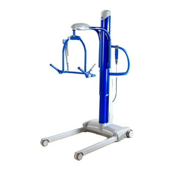
Product and Technical Description Introduction The Maxi Move is a mobile patient lifter and is used for transferring patients from bed or chair to the toilet or bath. The floor lift has a maximum safe working load (SWL) of 227 kg (500 lb). -
Page 7: Risk Assessment Checklist For Engineers
Product and Technical Description Risk Assessment Checklist for Engineers WARNING: IF IN DOUBT, CONTACT YOUR LOCAL ARJO REPRESENTATIVE. DO NOT TAKE UNNECESSARY RISKS. The following assessment MUST be made before carrying out servicing, repair work or installations: • Make sure the work area is adequately sized, suitably lit and at a reasonable temperature. -
Page 8: Suggested Tools
Recommended Spares Refer to PARTS LIST 001.25070.EN NOTE: This manual is intended to be used in reference to the Maxi Move manufactured in Canada (Serial number KMCXXXXX). For the Maxi Move manufactured in the UK or in Sweden, please refer to:... -
Page 9: Loctite Application
Product and Technical Description Loctite Application Refer to the manufacturer instructions on the container before use, in addition to the following information: Procedure for the correct use of Loctite 242 and Loctite 243 (Colour blue) Threadlocking: - Clean both of the joint faces with Loctite 7063 Cleaner or a lint-free cloth moistened with Acetone or another suitable volatile solvent. -
Page 10: Torque Data And Consumable Materials
Product and Technical Description Torque Data and Consumable Materials Thread retaining: Apply Loctite 243 when no threadlocking patch has been pre-applied. When replacing a part with pre-applied threadlocking, the part should be replaced by a new part using pre-applied threadlocking. NOTE: Grease 005.00031: Lenson white grease or equivalent can be used. - Page 11 Product and Technical Description Fig.2...
-
Page 17: Service Procedures
Service Procedures Service Procedures Procedures not Included in the PMS Jib/Jib roller- SP 17 Limit switch replacement- SP 15 Scale calibration- SP 6 Scale - SP 19 Strap replacement- SP 12 Combi T-bar attachment- SP 18 Combi spreader bars- SP20 Handset replacement- SP 11 Handle replacement- SP 14 Mast slider replacement- SP 16... -
Page 18: Service Procedure 1
Service Procedures Service Procedure 1 Check that the latest updates have been implemented • Check if there are any field correction bulletins, safety notices or technical bulletins that have been published since the last service. (These replace the previously used Technical Advice Notices (TAN) with status A (i.e. -
Page 19: Service Procedure 2
Service Procedures Service Procedure 2 Check the battery The battery power tester will load the battery with a high current (up to 60 A, depending on battery condition) for a short time and this will show the battery condition on a meter. WARNING! •... -
Page 20: Check The Battery Charger
Service Procedures Check the battery charger 700.24250 1) Connect the cable from the test rig to the charger. • Measure the voltage in the banana plug outlet of the rig. The voltage should be between 27.6 and 28 VDC. 2) Measure the current in the banana plug outlet of the rig. •... -
Page 21: Service Procedure 3
Service Procedures Service Procedure 3 Check all vital parts for corrosion and damage This verification will help preserve the safety and performance of the product. To Verify: 1) Front caster 2) Legs 3) Braked caster 4) Chassis 5) Column 6) Battery 7) Control box 8) Handle 9) Handset... -
Page 22: Service Procedure 4
Service Procedures Service Procedure 4 Full Feature Test Activation/ Function Actions Criteria for approval Validation No abnormal noises; unit reaches up/ Lift up/down Buttons Full stroke up and down down points as per specifications (see user manual) Legs open/ No abnormal noises; legs open fully Buttons Full opening and closing close... -
Page 23: Service Procedure 5
1. Medium Powered and Non-Powered Dynamic Positioning System (DPS) • Set up the ARJO Load Test Kit as shown and test to the Safe Working Load (SWL). • Release the load and remove the load test equipment. Check the hoist for any permanent deformation or damage. - Page 24 Service Procedures 3. Loop Small Two-Hook • Set up the ARJO Load Test Kit as shown and test to Safe Working Load (SWL). • Release the load and remove the load test equipment. Check the hoist for any permanent deformation or damage.
- Page 25 6. Combi Stretcher Frame and Strap Stretcher • Set up the ARJO Load Test Kit as shown and fill the 6 x 25 liter water containers (part of ST120) with water and test to 160kg. NOTE: The six water containers filled with water equal the SWL of 160kg.
-
Page 26: Service Procedure 6
Service Procedures Service Procedure 6 Scale Calibration Check Verified Scale Official scale calibration verification or re-verification should be take care by an approved organization in accordance with the standards stipulated by local authorities (as specified by each country). If a calibration is necessary on a verified scale, the new calibration will break the verification seals and will require a new verification by an approved organisation. -
Page 27: Service Procedure 7
Front 1) Place the Maxi Move on its handles, with the legs pointing upward. 2) Remove the bolt that holds the caster assembly using an 8 mm Allen key. The wheel of the caster cannot be dismantled. The caster must be changed. -
Page 28: Back
Service Procedures Back 1) Place the Maxi Move on its handles, the legs pointing upward 2) Remove the self-locking nut under the caster using a 13 mm socket and pull back the caster 3) Reinstall the caster. NOTE: Carefully place the caster components in the correct order (see Fig.11). The self-locking nut can be reused. -
Page 29: Service Procedure 8
Changing the Leg Assembly/Actuator Chassis opening 1) Slightly open the legs of the Maxi Move, to remove the pressure over the mechanical stop in the chassis. Failure to do so will prevent the base from opening. 2) Place the Maxi Move on its handles. Place an object under the battery holder to raise the chassis, so that no part of the chassis touches the ground. -
Page 30: Reassembly
Service Procedures Fig.13 Reassembly 1) Reinstall the cover and the nut. You may need to adjust the legs slightly to be able to slide the cover back on. NOTE: The 40 mm (1 1/2”) bolt must be used for the mast link attachment. DO NOT over- torque. -
Page 31: Service Procedure 9
Verification 1) Close the legs using the button located on the control panel. 2) Place the Maxi Move on its handle. 3) Measure the distance according to Fig.14. If the dimensions are out of tolerance, the legs must be adjusted. -
Page 32: Service Procedure 10
Service Procedures Service Procedure 10 Control box (PCB, Fuse, Switch, Keypad) Changing the PCB or the fuse in the fuse holder requires that the control box be opened. Opening the Control box 1) Remove the battery 2) Remove the control box cover’s 4 Torx screws. 3) Lift the control box up approx. - Page 33 Service Procedures Main PCB Fig.15 Inside view of the control box Fig.16...
-
Page 34: Dip Switch Settings
Service Procedures DIP Switch Settings The 492.00066 PCBA is, by default, configured in a safe state that limits the operation of the hoist. However, the 492.00066 can be configured by positioning a set of on-board DIP switches. The DIP switches use a binary configuration scheme. The procedure in this document shows how to properly set the switches according to the hoist in which the circuit is to be installed. - Page 35 Service Procedures PCBA CONFIGURATION TABLE PCBA Assembly PCBA Switch Position Switch Position Part Number Description (visual) Number PCBA IMF Maxi Move 492.00066-01 STANDARD JIB PCBA IMF Maxi Move 492.00066-02 EXTENDED JIB PCBA IMF Maxi Move 492.00066-33 EUROPEAN STANDARD JIB PCBA IMF Maxi Move 492.00066-34...
-
Page 36: Changing The Brake Board
Service Procedures Changing the Brake board 1) Remove main PCB (see above). 2) Disconnect all connectors to the brake board. 3) The PCB is attached with double side tape. Remove it by pulling on it. 4) Take the new PCB and pull back the liner on the double side tape. 5) Attach the PCB on the bottom off the control tower. -
Page 37: Closing The Control Box
6) Check that the gap between the control box and the backplate is consistently small. A bigger gap means that some wires are pinched behind the control box. 7) Replace the the 4 Torx screws. 8) Put back the battery, turn on the Maxi Move and perform a functional test (see SP 4) - Page 38 Service Procedures Fig.20...
-
Page 39: Service Procedure 11
Service Procedures Service Procedure 11 Replacing the Handset 1) Remove the battery 2) Using a small flat screwdriver or similar tool, open the handset door by prying on the tabs. 3) Slide the handset cable’s grommet from the control box. 4) Use the flat screwdriver to press on the the telephone jack’s release tab located on the handset cable inside the control box. -
Page 40: Service Procedure 12
Service Procedures Service Procedure 12 Replacing the Maxi Move Strap Fig.22... -
Page 41: Strap Removal
3) Remove the top cap by lifting it from the front. Some force may be necessary to remove it. 4) Remove the wire protecting cap. 5) Cover the handles to protect them, and place the Maxi Move down on the floor. 6) Remove the strap roller and the pivot pin on both sides. - Page 42 Service Procedures Fig.24 8) Remove the starlock washer on the jib pin. Remove the strap. For the strap with a wire clipped inside, carefully remove the wire from the clip. 9) Take the two new straps and compare strap lengths. ALWAYS PUT THE SHORTEST STRAP ON THE SIDE OF THE WIRE.
- Page 43 Service Procedures 10) Slowly turn the top of the actuator until you can see the strap pivot across the hole on the front of the column. 11) Insert a M4 screw inside the pin and carefully pull out the pin. It might be necessary to lift the spring wire in the inner casting to relieve some pressure on the pin.
-
Page 44: Top Cover Reassembly
Service Procedures Top Cover reassembly Fig.28 1) Turn the ribbed wheel at the top of the actuator to align the hole in the actuator with the hole in the top casting outer mast. Slide the pin inside the hole to keep it in position. 2) Position the emergency handle assembly over the ribbed wheel so the handle lines up with the back of the column. -
Page 45: Verification
Service Procedures Fig.29 Fig.30 Verification Once the cover is installed, raise and lower the column throughout its full stoke and check for any issues (noise, vibration, incorrect assembly). Perform a safe working load test (see SP 5 [local requirement]) and check the up/down function of the column. -
Page 46: Service Procedure 13
Service Procedures Service Procedure 13 Replacing the Mast Actuator Fig.31 Removing the Mast 1) Raise the column enough to see the actuator screw head in the inner mast. 2) Remove the control box (see SP. 10) and the top plastic cap. 3) Remove the four screws that secure the battery bucket to the backplate and the two screws that holds the backplate to the chassis. -
Page 47: Removing The Actuator
Service Procedures Removing the Actuator 1) Pull out the emergency lowering pin and remove the screw that holds the ribbed wheel in the actuator. 2) Remove the two screws that secure the actuator. These screws are held in with theadlocker, so be careful not to strip the heads. -
Page 48: Installing The Mast
Service Procedures Installing the Mast 1) Secure the wires on the column to make sure that no wires get pinched between the mast and the chassis. 2) Replace the mast over the chassis. Check wire positions before completely lowering the mast to the chassis. -
Page 49: Service Procedure 14
Service Procedures Service Procedure 14 Replacing/Adjusting the Handle Fig.34 Removing the Handle 1) Lift the red emergency handle. Remove the screw that secures the red ribbon attached to the pin. 2) Remove the upper cap, the emergency handle assembly and the flexible cable protector (see SP 11). -
Page 50: Replacement
4) Replace the control box cover and the top plastic cover. 5) Move the Maxi Move to validate that the handle free play is correct. -
Page 51: Service Procedure 15
Service Procedures Service Procedure 15 Changing the Limit Switch Anti-crush / Lower Limit Fig.35... -
Page 52: Upper Limit
Service Procedures 1) Lower the lift column completely with the handset. 2) Lift the red emergency handle. Remove the screw that holds the red ribbon attached to the 3) Remove the upper cap (see SP 11), the emergency handle assembly and the flexible cable protector. - Page 53 Service Procedures 5) Replace the top casting inner with the correct orientation. Use new bolts that have pre- applied adhesive. 6) Slide the inner mast back inside the outer mast. Be careful to place the sliders correctly if they fell out during the repair. 7) Put back the top casting outer mast with the cable roller and the strap roller.
-
Page 54: Service Procedure 16
Service Procedures Service Procedure 16 Slider Adjustment Replacement Fig.36 Four sliders are placed between the two extrusions to lower friction and to provide smooth movement. The two sliders that take the load (lower front and upper rear) are attached and held in hole in the extrusion. -
Page 55: Lower Slide
Service Procedures 2) Slowly turn the adjustment screw clockwise to add pressure over the slider. Try to raise and lower the column during the adjustment to find the best adjustment. Too much pressure will restrict the mast’s movement and too little will produce too much play between the columns. -
Page 56: Service Procedure 17
Service Procedures Service Procedure 17 Jib / Jib roller / Jib cover Jib removal 1) See SP 12 - Strap removal for accessing the jib. 2) Remove the two screws under the jib cover. Push the clip on the top cover and lift to remove the upper cover. -
Page 57: Changing The Jib Top Cover
Service Procedures Changing the Jib Top Cover Remove the two screws under the jib cover. Push the clip on the top cover and lift to remove the upper cover. Replace the cover and the screws. DO NOT overtighten screws. Changing the Jib Bottom Cover (Non-Scale units or Non-European Scales) 1) Remove the upper cover. -
Page 58: Service Procedure 18
Service Procedures Service Procedure 18 Combi Attachment Fig.39 Inspection 1) Remove the jib top cover. Use a 30 mm socket to check the torque on the M20 nut that retains the lift support unit. 2) Check that a force between 2 and 3 kg is required to rotate the spreader bar in either direction. -
Page 59: T-Bar Removal
4) Remove the friction adjustment’s 10 mm (3/8”) setscrew, the spring and the nylon block. 5) Remove the battery and place the Maxi Move on its back. 6) Remove the 6 mm (1/4”) setscrew on the combi adaptor and rotate the T-Bar to remove the five ball bearing balls within the T-Bar. -
Page 60: Service Procedure 19 6
Service Procedures Service Procedure 19 Scale Removal/Installation NOTE: When changing the scale, use the FULLY ASSEMBLED scale repair kit, which includes the T-bar fully assembled at the factory. Fig.40... -
Page 61: Removing The Scale
If the inclination is out of range, use the taper shim provided with the kit to set the scale at the correct angle (each shim adds/removes 0.5 degrees). 5) Connect the scale. Turn on the Maxi Move. The scale display must illuminate and show “0.0”. -
Page 62: Service Procedure 20
Service Procedures Service Procedure 20 Combi Spreader Bars 1) Visually check the jib for damage and defects to the paint work and the welded joints. Make sure that the end plugs are installed. Recommend replacement of any defective parts. Locking clip Safety latch Steering pins Leaf spring... -
Page 63: Four-Point Dps Pivot Point
Service Procedures Four-Point DPS Pivot Point Visually check the condition of the two bushings in the T-bar. Replace if necessary. Locking clip Steering pins Leaf spring NOTE: Check the welding of the two steering pins. If loose, replace the Safety latch spreader bar. -
Page 64: Four-Point Powered Dps Spreader Bar
Service Procedures Four-Point Powered DPS Spreader Bar NOTE: The powered DPS pivot point configuration is the same as the non powered with the exception of a powered actuator and the friction washers being manufactured from nylon. Lift support Friction washer Tube end cap M10 nylon nut Washer... - Page 65 Service Procedures Fig.44 1) Check the condition of the hand grip knob (a) recommend replacement if necessary. Secure the new hand grip knob in accordance with the manufacturers instructions. 2) Remove the two caps (b) from the pivot points and use a 17 mm socket to check the torque on the two M10 nyloc nuts (c).
-
Page 66: Sling Checks
Service Procedures Sling Checks... - Page 70 MD 87841 ISO 13485 If your country is not listed here, please contact your local distributor or: ...with people in mind. ARJO International AB, Box 61, S-241 21 Eslov, SWEDEN Tel +46 413 64500. Fax +46 413 555586. www.arjo.com MEMBER OF THE GETINGE GROUP www.arjo.com...
Need help?
Do you have a question about the MAXI MOVE and is the answer not in the manual?
Questions and answers
why won't the lift stay up when there is weight on it
The Arjo MAXI MOVE lift may not stay up when there is weight on it if the battery is low or completely drained. When the battery is low, the lift may enter sleep mode and become inoperable until the battery is recharged. An audible warning and low battery icon will indicate this condition. Proper battery maintenance, including recharging before the battery is fully drained, is necessary for correct lift operation.
This answer is automatically generated