Arjo MAXI MOVE Maintenance And Repair Manual
Hide thumbs
Also See for MAXI MOVE:
- Maintenance and repair manual (70 pages) ,
- Instructions for use manual (52 pages) ,
- Operating and product care instructions (50 pages)

Related Manuals for Arjo MAXI MOVE


Summary of Contents for Arjo MAXI MOVE
- Page 1 MAXI MOVE MAINTENANCE AND REPAIR MANUAL Reference Copy Printed 3:37 pm, Aug 22, 2006 Check occasionally for new editions. For internal use only! 09.KM.00/3GB August 2006...
- Page 2 For technical data, measurements and upgrades not found in this guide, please refer to the Reference Copy Operating Instructions. Printed 3:37 pm, Aug 22, 2006 Check occasionally for new editions.
-
Page 3: Table Of Contents
Reference Copy CONTENTS: Printed 3:37 pm, Aug 22, 2006 Check occasionally for new editions. Product and Technical Description ..................4 General............................5 Risk Assessment Checklist for Engineers ................6 Service Matrix..........................7 Suggested Tools ........................8 Standard tool kit........................8 Recommended Spares ...................... -
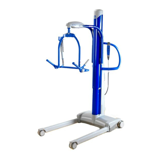
Page 4: Product And Technical Description
Printed 3:37 pm, Aug 22, 2006 The Maxi Move is a mobile patient lifter and is used for transferring patients from bed or chair to Check occasionally the toilet or bath. The hoist has a Safe Working Load (SWL) of 228kg (501 lb): refer to NOTE. -
Page 5: General
Un- authorised modifications on any ARJO equipment may affect its safety and are in breach of any warranty on it. ARJO will not be held responsible for any accidents, incidents or lack of performance that occur as a result of un-authorised modifications to its products. -
Page 6: Risk Assessment Checklist For Engineers
• You must comply with all local site safety rules, report any incident or accident to the site safety supervisor or equivalent. Use the ARJO reporting procedure. • If necessary use Hard Surface Wipes (Alcohol Impregnated) to decontaminate a machine before carrying out any work. -
Page 7: Service Matrix
Printed 3:37 pm, Aug 22, 2006 Service 12 Monthly 24 Monthly Check occasionally MAXI MOVE for new editions. Refer to 12 Monthly Service Procedure , page 24 Refer to 24 Monthly Service Procedure, page 36 NON-POWERED AND POWERED DYNAMIC POSITIONING SYSTEM (DPS) -
Page 8: Suggested Tools
Suggested Tools Reference Copy Printed 3:37 pm, Aug 22, 2006 Standard tool kit. Check occasionally Special Tool ST252. for new editions. 2 x 20kg weights ST219. Socket Allen Key: (4mm ST82) (5mm ST274) (6mm ST55) (8mm ST87). Drift ST288. Ball End Allen Key (4mm) ST292. Starlock Washer Installation Tool (ST295). -
Page 9: Loctite Application
Reference Copy Printed 3:37 pm, Aug 22, 2006 Loctite Application Check occasionally for new editions. Refer to the manufacturer instructions on the container before use, in addition to the following information. Procedure for the correct use of Loctite 242 and Loctite 243 (Colour blue) – Threadlocking: Clean both of the joint faces with Loctite 7063 Cleaner or a lint-free cloth moistened with Acetone or another suitable volatile solvent. -
Page 10: Torque Data And Consumable Materials
Reference Copy Torque Data and Consumable Materials Printed 3:37 pm, Aug 22, 2006 Check occasionally NOTE: It is acceptable to use alternative equivalents to the product items listed. The for new editions. alternative equivalents must be authorised by the Technical Support department as suitable for use Thread retaining: Apply Loctite 243 when no threadlocking patch has been pre-applied. - Page 11 Reference Copy Printed 3:37 pm, Aug 22, 2006 Check occasionally for new editions. 20Nm (14,8 lbf ft) Loctite 243 Engrease L21M/Lenson/Castrol Loctite 638 Engrease L21M/Castrol 8,7Nm (6,4 lbf ft) Loctite 243 Lenson White Grease Shell Cassida Statoil Uniway Lix 62 8,7Nm (6,4 lbf ft) Loctite 243 Shell Cassida...
- Page 12 Reference Copy Printed 3:37 pm, Aug 22, 2006 Check occasionally for new editions. Silicone Lenson White Loctite Superflex Grease 5 Nm (3,7 lbf ft) Loctite 243 Loctite 415 Loctite 454...
- Page 13 Reference Copy Printed 3:37 pm, Aug 22, 2006 Check occasionally for new editions. Scale 72Nm (52 lbf ft) Loctite 243 60Nm (44 lbf ft) Pre-treated locking Loctite 243 Engrease L21M/Castrol/vaselin Tufloc screw Replaced by extended version Loctite 243 Sapphire Precision Lube Engrease L21M/Castrol/ vaselin...
- Page 14 Reference Copy Printed 3:37 pm, Aug 22, 2006 Check occasionally for new editions. Loctite 415 25Nm (18 lbf ft) Nyloc Bostik 1782 Attachment see page Nyloc and Loctite 243...
- Page 15 Reference Copy Tufloc screw Printed replaced. Now use 3:37 pm, Aug 22, 2006 60Nm (44 lbf ft) Loctite 243 Check occasionally Pre-treated for new editions. locking Bostik 1782 Sapphire Precision Lube Attachment see page 19 Nyloc/ Loctite 243 60Nm (44 lbf ft) Tufloc screw Pre-treated Replaced by...
-
Page 16: Monthly Service Procedure
12 Monthly Service Procedure Reference Copy Printed 3:37 pm, Aug 22, 2006 WARNING: OBEY ALL RELEVANT SAFETY PRECAUTIONS. Check occasionally for new editions. Visually check the general condition of all external parts. Check that the latest updates have been implemented: - Check if there are any Field Correction Bulletins, Safety Notices or Technical Bulletins that have been published since the last service. - Page 17 Operate the raise/lower function of the hoist through its full operating range and listen for Reference Copy any abnormal noise from the actuator. If the actuator is noisy recommend replacement of Printed the actuator. 3:37 pm, Aug 22, 2006 Check occasionally for new editions.
- Page 18 Mechanical Reference Copy With the jib raised to approximately its mid lifting height: Printed 3:37 pm, Aug 22, 2006 Remove the battery from the hoist. Check occasionally Remove the top cover from the mast. for new editions. Using the Wind Down Tool provided loosen the M12 cap screw approximately four full turns enough to allow the actuator to rotate freely: refer to Figure below.
-
Page 19: Jib And Attachments
Jib and Attachments Reference Copy Printed (Torques and consumable material according to page 10-15). 3:37 pm, Aug 22, 2006 Check occasionally WARNING: OBEY ALL RELEVANT SAFETY PRECAUTIONS. for new editions. Refer to Figure below: 1.Remove the jib top cover and use a 30mm Socket to check the torque on the M20 locknut that retains the lift support/teebar to the jib. - Page 20 T Bar to Jib Reference Copy Printed 3:37 pm, Aug 22, 2006 Check occasionally for new editions. Refer to Figure above. Check the clearance between the jib and the T bar this should be between 1 and 2mm and can only be altered by replacing the bushes there is no other adjustment.
-
Page 21: Four Point Dps (Combi And Dedicated)
Four Point DPS Pivot Point Reference Copy Printed 3:37 pm, Aug 22, 2006 Check occasionally for new editions. Check pivot pin, if loose replace hanger bar ! - Visually check the condition of the four igus bushes in the T bar: replace if necessary. Four Point DPS (Combi and Dedicated) Visually check the welds around the lifting lugs for cracks or any sign of deterioration. -
Page 22: Four Point Powered Dps (Combi Illustrated)
Reference Copy Printed 3:37 pm, Aug 22, 2006 Four Point Powered DPS (Combi illustrated) Check occasionally for new editions. NOTE: The powered DPS pivot point configuration is the same as the non powered with the exception of a powered actuator and the friction washers being manufactured from nylon. -
Page 23: Jib With Scale Fitted (Combi Illustrated)
Reference Copy Jib with Scale Fitted (Combi illustrated) Printed 3:37 pm, Aug 22, 2006 Check occasionally Use a 4mm Allen Key to remove the three (later models five) screws (a) that retain for new editions. the scale top and bottom covers (b). Remove the top cover. NOTE: If any adjustment of the load cell screws (c) is necessary a recalibration process performed and verified by an approved organisation will be... -
Page 24: Mast Assembly And Push Handle
Mast Assembly and Push Handle Reference Copy Printed 3:37 pm, Aug 22, 2006 (Torques and consumable material according to page 10-15). Check occasionally for new editions. WARNING: OBEY ALL RELEVANT SAFETY PRECAUTIONS. NOTE: The lift band assemblies are replaced at 24 monthly service intervals. Refer to Figures below. - Page 25 Reference Copy Visually check the condition of the inner mast (b) look for signs of scuffing on the paintwork Printed 3:37 pm, Aug 22, 2006 this would be an indication of worn upper and lower mast bearings (c). If scuffing is evident Check occasionally replace the upper and lower mast bearings.
- Page 26 Push Handle Adjustment Plastic Screws Reference Copy Printed 3:37 pm, Aug 22, 2006 Check occasionally for new editions. CAUTION: DO NOT LEAVE THE PLASTIC SCREWS FULLY TIGHTENED AGAINST THE MAST WHEN ADJUSTING THE PUSH HANDLE. THIS WILLNOT ALLOW A SMOOTH OPERATION WHEN RAISING/ LOWERING THE MAST. Visually check the condition of the slipper mouldings (a).
-
Page 27: Chassis Assembly
Chassis Assembly Reference Copy Printed 3:37 pm, Aug 22, 2006 (Torques and consumable material according to page 10-15). Check occasionally for new editions. WARNING: OBEY ALL RELEVANT SAFETY PRECAUTIONS. Visually check the integrity of all welds and paintwork for defects. Visually check the condition of the plastic leg extrusions (a) if damaged recommend replacement. -
Page 28: Sling Checks
NOTE: The use of this gauge is the only approved method of checking the serviceability of the ARJO plastic sling clip and no other method should be used. Check that the Safe Working Load (SWL) label is legible if necessary mark the SWL with an indelible marker pen. -
Page 29: Load Test (Local Requirement)
6. Combi Stretcher Frame and Strap Stretcher Set up the ARJO Load Test Kit as shown and fill the 6 x 25 Litre water containers (part of ST120) with water and test to 160kg. NOTE:The six water containers filled with water equal the SWL of 160kg. - Page 30 Reference Copy 1. Medium Powered and Non-Powered DPS 2. Loop Medium (illustrated) and Walking Printed 3:37 pm, Aug 22, 2006 Jacket Two Hook (not illustrated) Check occasionally for new editions. Tool No. Description Tool No. Description ST164 Handset and Load ST164 Handset and Load Cell...
- Page 31 Reference Copy 3. Loop Small 4. Loop Large Four Hook Printed 3:37 pm, Aug 22, 2006 Check occasionally for new editions. Tool No. Description Tool No. Description ST164 Handset and Load ST164 Handset and Load Cell Cell ST165 Load Test Strap ST165 Load Test Strap (short)
- Page 32 Reference Copy 5. Large Powered and Non-Powered DPS 6. Combi Stretcher Frame and Strap Printed 3:37 pm, Aug 22, 2006 Stretcher Check occasionally for new editions. Tool No. Description Tool No. Description ST40 Load Frame & Straps ST120 Water Barrel ST164 Handset and Load Cell...
-
Page 33: Pcb:s And Wiring Diagram
PCB:s and Wiring Diagram Reference Copy Printed 3:37 pm, Aug 22, 2006 CAUTION: WEAR ELECTRO STATIC DISCHARGE (ESD) EQUIPMEMT WHEN HANDLING Check occasionally PRINTED CIRCUIT BOARDS (PCB’S). for new editions. Console push Motor Control buttons J1, J2 Motor Control Handset J1, J2 Orange wire this side... - Page 34 Reference Copy Printed 3:37 pm, Aug 22, 2006 Check occasionally for new editions. Battery Mast Actuator/Start-Stop switch Blue wire BDI JJ2, JJ5 Emergency lowering switch this side BDI JJ2, JJ5, JJ6 BDI JJ6 PCB Motor Control...
- Page 35 Reference Copy Printed 3:37 pm, Aug 22, 2006 Check occasionally for new editions. Wiring Diagram...
-
Page 36: Monthly Service Procedure
24 Monthly Service Procedure Reference Copy Printed 3:37 pm, Aug 22, 2006 (Torques and consumable material according to page 10-15). Check occasionally for new editions. WARNING: OBEY ALL RELEVANT SAFETY PRECAUTIONS. Lift Band Removal and Replacement Position the hoist in a suitable work area that will allow enough room to remove the mast assembly from the chassis. - Page 37 Remove the pivot pin and roller from each side of the mast. Reference Copy Printed 3:37 pm, Aug 22, 2006 Check occasionally for new editions. CAUTION: WHEN REMOVING A POWERED DPS JIB DISCONNECT THE ELECTRICAL SPADE CONNECTORS FROM THE STAINLESS BUS BARS AND PULL OUT THE CONTACT PLUNGER BEFORE REMOVING THE JIB.
- Page 38 Carefully slide the jib up the mast enough to gain access to the lift bands then remove the Reference Copy starlock washers and release the lift bands and buckles from the carriage in the jib: refer to Printed Figure below. 3:37 pm, Aug 22, 2006 Check occasionally Carefully slide the jib from the mast making sure not to lose the four carriage rollers:...
- Page 39 Reference Copy Install an M4 screw (slave item) to the pin and carefully pull the pin from the inner casting Printed 3:37 pm, Aug 22, 2006 enough to remove the lift band. Check occasionally for new editions. Install the new lift band making sure that the flush side of the lift band is facing outwards. Push the pin through the lift band and under the spring that retains the pin in position.
- Page 40 Lightly lubricate the roller pivot pins: Reference Copy Printed 3:37 pm, Aug 22, 2006 Check occasionally for new editions. Check the the carriage rollers and the guide blocks on the jib. Replace if necessary. Lightly lubricate the roller spindles and guide blocks. Protect the push handle and carefully lay the hoist on the push handle.
- Page 41 Attach the lift band and buckle cover to the jib spindle, retain in position with a new starlock Reference Copy washer using ST295 (Starlock Washer Installation Tool). Repeat this process on the Printed remaining lift band. 3:37 pm, Aug 22, 2006 Check occasionally for new editions.
- Page 42 Reference Copy Function check the hoist according to section 12 Monthly Service Procedure, page 16 Printed 3:37 pm, Aug 22, 2006 Check occasionally Refer to section Load Test on page 29 and perform a Load Test (local requirement). for new editions.
-
Page 43: Repair Procedures
Repair Procedures Reference Copy Printed 3:37 pm, Aug 22, 2006 Mast Actuator Removal and Replacement Check occasionally for new editions. (Torques and consumable material according to page 10-15). WARNING: OBEY ALL RELEVANT SAFETY PRECAUTIONS. Position the hoist in a suitable work area that will allow enough room to remove the mast assembly from the chassis. - Page 44 Remove the pivot pin and roller from each side of the mast. Reference Copy Printed 3:37 pm, Aug 22, 2006 Check occasionally for new editions. CAUTION: WHEN REMOVING A POWERED DPS JIB DISCONNECT THE ELECTRICAL SPADE CONNECTORS FROM THE STAINLESS BUS BARS AND PULL OUT THE CONTACT PLUNGER BEFORE REMOVING THE JIB.
- Page 45 Carefully slide the jib up the mast enough to gain access to the lift bands, remove the Reference Copy starlock washers and release the lift bands and buckles from the carriage in the jib:. Printed 3:37 pm, Aug 22, 2006 Carefully slide the jib from the mast making sure not to lose the four carriage rollers: Check occasionally for new editions.
- Page 46 Reference Copy WARNING: DO NOT POSITION YOUR FINGERS BETWEEN THE INNER AND Printed 3:37 pm, Aug 22, 2006 OUTER MAST WHEN REMOVING THE MAST TO CHASSIS BOLTS. Check occasionally for new editions. Use a 6mm Socket Allen Key to remove the two M10 countersunk mast to chassis bolts : Mast to chassis bolts Screw and nut holding the...
- Page 47 Use a 5mm Socket Allen Key to remove the four M6 cap head screws and spacers that Reference Copy retain the actuator in position. Printed 3:37 pm, Aug 22, 2006 Check occasionally for new editions. Carefully ease the actuator out from the bottom of the inner mast, motor first . NOTE: To ease disassembly it may be necessary to manually unwind the actuator stabilising tube in top of the actuator so that it just protrudes above the top of the...
- Page 48 If lubrication of the existing actuator is required use grease on the screw thread or if Reference Copy required install the new actuator. Make sure to align the holes in the actuator with the cap Printed 3:37 pm, Aug 22, 2006 screw holes in the outer mast.
- Page 49 Check the condition of the carriage rollers and the guide blocks. Replace if necessary. Reference Copy Printed Lightly lubricate the roller spindles and guide blocks on the jib. 3:37 pm, Aug 22, 2006 Check occasionally for new editions. Lubricate spindle Carriage roller Contact plunger...
- Page 50 Reference Copy Printed 3:37 pm, Aug 22, 2006 Check occasionally for new editions. Slide the jib assembly down the mast enough to gain access to the outer mast top casting . Install the roller and pivot pin to the outer top mast casting. Make sure the dimple in the pivot pin locates in the domed protrusion in the top mast casting.
- Page 51 Fax: 22 57 06 52 Certified ISO 14001 by If your country is not listed here, please contact your local distributor or: ARJO International AG, Florenzstrasse 1 d, Postfach-PO-Box, CH- ...with people in mind. 4023 BASEL, SWITZERLAND, Tel. +41 61 337 97 97, Fax: +41 61 331 47 80.
Need help?
Do you have a question about the MAXI MOVE and is the answer not in the manual?
Questions and answers
the lift goes up but does not come down and the red wrech lights up. a Nurse raised it all the way up and this happened