Table of Contents
Advertisement
Quick Links
Advertisement
Table of Contents

Related Manuals for GCC Technologies JF-2418UV


Summary of Contents for GCC Technologies JF-2418UV
- Page 1 JF-2418UV User Manual http://www.GCCworld.com GCC Club V.1 2022 Mar...
- Page 2 JF-2418UV User Manual Dear Sir / Madam, Thank you for choosing GCC and the JF-2418UV Flatbed Printer. You can be assured that this machine meets the highest safety standards while using technological innovations shared by no other UV printer. JF-2418UV Flatbed Printer is backed by GCC, a truly international company that is dedicated to help your business grow.
- Page 3 JF-2418UV User Manual Release Note Version Change V.1 2021 Nov. Add JF-2418UV User Manual...
-
Page 4: Table Of Contents
1.6 Ink Operating and Storage Environment ............... 10 Chapter 2 Equipment Main Body Introduction .................11 2.1 Flatbed UV Printer ......................11 2.1.1 JF-2418UV Flatbed Printer Key features ............12 2.2 JF-2418UV Appearance ..................... 13 2.2.1 JF-2418UV Front View ..................13 2.2.2... - Page 5 JF-2418UV User Manual 5.2.3 Add Image Setting ....................60 5.2.4 Editor ........................64 5.2.5 External Software Printing Setups ..............81 5.2.6 JOB Server Settings ..................... 83 5.2.7 How to User Auto Serialization in FlexiPRINT GCC Edition-ADVANCED ..89 5.3 How To Set The color-white/white-color/color-white-color printing ...... 96 5.3.1...
- Page 6 6.9 How to fill GCC Inkjet Coolant ..................166 Chapter 7 Caldera Installation ......................167 7.1 Caldera Installation ......................167 7.1.1 How to set GCC JF-2418UV Driver ..............167 7.1.2 Launch Caldera RIP ................... 170 Chapter 8 Reference Parameter Settings ..................175 Q &...
-
Page 7: Warning
JF-2418UV User Manual Chapter 1 Introduction 1.1 Warning These symbols are applied in the user manual for the safety precaution and to prevent equipment from damage. These symbols are informational notice. Please do understand meanings for each of these symbols and its related safety precautions prior operate the equipment. -
Page 8: Inks Safety Information
JF-2418UV User Manual Ground Wire The symbol indicates the machine should be grounded before conducting any maintenance or cleaning operation due to possible electrostatic discharge. Printing The symbol indicates that during Warning the printing process do not put your hands in the printing area to avoid injury. -
Page 9: First-Aid Measures
JF-2418UV User Manual Can cause dermatitis or irritation that may last for hours or days, but Skin unlikely to result in permanent harm. Can cause severe irritation, tearing, and burns that may eventually lead to permanent impairment, including blindness. Can cause severe irritation to mouth, throat, and stomach, may further Swallow inflict abdominal discomfort, nausea, vomiting and diarrhea. -
Page 10: Equipment Installation Precautions
Equipment Installation Precautions GCC JF-2418UV shall be installed in a relatively clean, free from dust environment and the surface for the equipment to be installed shall be stable and flat. We suggest that you install the equipment in an air-conditioned environment to control the appropriate temperature and humidity. -
Page 11: Ink Operating And Storage Environment
JF-2418UV User Manual 1.6 Ink Operating and Storage Environment Store the inks away from direct sunlight or other lighting sources, including fluorescent lighting. Store them away from acids, alkalis, and oxidizing material as well. Additionally, keep container tightly closed in a dry, cool, well ventilated place. -
Page 12: Chapter 2 Equipment Main Body Introduction
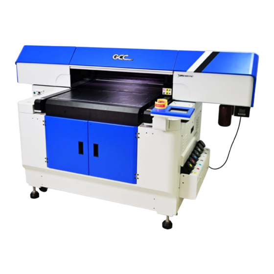
JF-2418UV User Manual Chapter 2 Equipment Main Body Introduction JF-2418UV flatbed printer is designed for printing on rigid, cylinder and roll materials. Cylinder or roll materials are only available with the rotary attachment or roll to roll system optional items. -
Page 13: Jf-2418Uv Flatbed Printer Key Features
JF-2418UV User Manual 2.1.1 JF-2418UV Flatbed Printer Key features Features: 1. Maximum print area: 610x457mm (24”x18”) 2. Media thickness up to 300mm (11.8”) 3. Print resolution of up to 1,200dpi 4. Acceptable media weight up to 15Kg 5. Maximum Print Speed: 3.75 m 6. -
Page 14: Jf-2418Uv Appearance
JF-2418UV User Manual 2.2 JF-2418UV Appearance 2.2.1 JF-2418UV Front View N. Toolbox M. Front lid (Front hood) L. Print head set A. Maintenance B. Barometer K. Temperature controller C. LED lamp D. Alignment J. Waste ink ruler bottle I. Touch screen control panel E. -
Page 15: Jf-2418Uv Rear View
JF-2418UV User Manual 2.2.2 JF-2418UV Rear view V. Hot water heating system U Side cover O. Rear door P. Fuse Q. Power socket R. USB S. Ethernet T. Power switch 2.2.3 JF-2418UV Parts Description Parts Name Description A. Maintenance Maintain print head cleanness B. - Page 16 E. Front Door Keep closed. Unless in necessary to open it up for loading the material. F. Printing Area The area where JF-2418UV conducts the inkjet printing. G. Bulk Ink supply Where the bulk ink bottle are installed system H. Emergency Stop Stop the machine under emergent condition.
-
Page 17: Chapter 3 Installation Procedure
JF-2418UV User Manual Chapter 3 Installation Procedure 3.1 Machine Setup 3.1.1 Turn On The Power Step 1 Please check the ink chip is inserted properly into the corresponding slot. Step 2 Fill each color of ink bottle with corresponding color of ink. It is suggested to horizontally shake the White ink 15 times before filling in the bottle or stir the White ink manually before printing. -
Page 18: Set Ink Flow To Printer Heads
JF-2418UV User Manual 3.1.2 Set Ink Flow To Printer Heads Step 1 Remove the thumbscrew and open the left cover. Step 2 Open the ink valve. Ink valve is opened Ink valve is closed Step 3 1. Entre FLATBED mode. - Page 19 JF-2418UV User Manual Step 4 Ink install flow: Start Ink Install Procedure? ENTER CANCEL 1.Empty waste ink bottle. 2.Open the ink valves of print Head. ENTER CANCEL Open the ink valves of ink bottle as shown ENTER CANCEL Insert the chips of each color. Do not...
-
Page 20: Software Setup
JF-2418UV User Manual 3.2 Software Setup Softkey Installation Instructions 3.2.1 Insert the DVD and run the installation and follow the instructions. Disable your antivirus software before installing FlexiPRINT GCC Edition. When the Install Manager dialog comes up, enter your password here:... - Page 21 JF-2418UV User Manual 2. Select "I am new to the SAI Cloud", then select Create Account and click confirm 3. Select "Activate Now"...
- Page 22 JF-2418UV User Manual 4. The FlexiPRINT GCC Edition is installed. 5. Select "Yes,I want to restart my computer now."...
-
Page 23: Chapter 4 Control Panel
JF-2418UV User Manual Chapter 4 Control Panel This section mainly describes JF-2418UV Flatbed Printer’s touch screen control panel, work flows and key operations. 4.1 Control Panel Workflow Operating work flow:... - Page 24 JF-2418UV User Manual Control panel flow:...
- Page 25 JF-2418UV User Manual Operating work flow:...
- Page 26 JF-2418UV User Manual Control panel flow: USER SET NOZZLE CHECK POWER SAVE VACUUM SYSTEM INFO OPTION AUTO CLEANING MANUAL CLEANING INK REMAINIING MAINTENANCE NETWORK RESTORE PH GAP AUTO DETECTION PARAMETER: DEFAULT SET1 VACUUM SET3 SET2 LED POWER X:_______ Y:_______ NORMAL...
- Page 27 JF-2418UV User Manual Operating work flow:...
- Page 28 JF-2418UV User Manual Control panel flow: REAR: FRONT:...
- Page 29 JF-2418UV User Manual Operating work flow: Control panel flow: IP:192.168.102.249 Sub Mask:255.255.255.0 Gateway:192.168.102.250 RESTORE DEFAULT:YES MAC Address: 00:CF:52:72:03:01...
- Page 30 JF-2418UV User Manual PAUSE while printing: Users can pause on the printing job by pressing the PAUSE button and proceed to cleaning procedure to improve printing quality. Operating work flow: Control panel flow:...
-
Page 31: Control Panel Layout Description
JF-2418UV User Manual 4.2 Control Panel Layout Description Control Panel Layout Description Function Description Setting Default Media sizing Adjustment menu setup key for roll Optional media printing settings (work with roll to roll system) ROLL (Media Roll) (AMC) Automatically detect... - Page 32 JF-2418UV User Manual (LOAD MADIA) Set/Place media height (AMC) Automatically detect the media height (ORIGIN) Set printing origin → MENU USER SET 1) USER DEFAULT : Initial parameters Can store up to 3 User DEFAULT settings groups 2) SET1~3 parameter settings...
- Page 33 JF-2418UV User Manual Normal print head cleaning NORMAL Powerful print head cleaning POWERFUL Purge white ink for print head cleaning after the defined printing passes are performed. Select PASS TO WHITE CLEAN can define the number of PASS TO WHITE passes for white ink clean.
- Page 34 JF-2418UV User Manual POWER SAVE sec., 1 min., 3 min. and 5 min. → MENU VACUUM Vacuum function is to ensure ON/OFF material’s flatness. This setting can be enabled or disabled. Default is enabled. If choose disable, then VACUUM there will be no vacuum sucking during the printing operation.
- Page 35 JF-2418UV User Manual Ink-install flow INK INSTALL/DRAIN Ink-drain flow → MENU SYSTEM INFO MODEL:Display the equipment dimension and model based on factory version settings FW:Display Firmware version serial number based on factory version SYSTEM INFO settings. FPGA:Display FPGA version serial number based on factory version settings.
- Page 36 JF-2418UV User Manual → MENU NETWORK IP address IP ADDRESS MAC address MCA ADDRESS → MENU RFACTORY DEFAULT Reset machine setting to factory default. FACTORY DEFAULT → MENU PH GAP AUTO DETECTION Automatically detect the gap between print head and media.
- Page 37 JF-2418UV User Manual Set the period of time that the OPTIONAL machine can be operated. The Time Locker function can be used for hire of a machine to schools or organizations TIME LOCKER to manage the rent duration of a hired machine.
- Page 38 JF-2418UV User Manual MANUAL CLEANING Circulation of white ink print head WHITE CIRCULATION...
-
Page 39: Chapter 5 Operating The Jf-2418Uv
JF-2418UV User Manual Chapter 5 Operating the JF-2418UV 5.1 Hardware Operation 5.1.1 How to Set Flatbed Printing Mode NOTICE: The factory setting of the height between print media and print head is 1.5mm. If the height between print media and print head is more than 2mm, it may cause ink droplet misting or splashing and lead to a grainy and uneven printing. - Page 40 JF-2418UV User Manual 3. Continue to print by uni-direction: The throughput may be decreased and the quality may be slightly affected, because the print mode is forced to set to uni-direction and the print head gap is not the optimum value.
- Page 41 JF-2418UV User Manual Workflow A. Set the “PH Gap Auto Adjustment” to be “ON” on control panel: (The default setting)
- Page 42 JF-2418UV User Manual B. Set the “PH Gap Auto Adjustment” to be “OFF” on the control panel:...
-
Page 43: How To Print On Rigid Material
Please load the rigid material correctly according to following steps. Step 1. Entre FLATBED mode. Step 2. Select MENU. Step 3. Select USER SET. Step 4. Select DEFAULT and select BACK icon . Step 5. Place print media on the lower right corner of the platen of JF-2418UV. (CAUTION) - Page 44 JF-2418UV User Manual Step 6. Select LOAD MADIA, and then adjust the height of platen of JF-240 to proper position. (Note: the printing side should always be adjusted BELOW the print head.) Step 7. Select AMC to autamatically detect the height between print media and print head.
- Page 45 JF-2418UV User Manual Step 5. Place print media on platen of JF-2418UV. Step 6. Select LOAD MADIA, and then adjust the height of platen of JF-240 to proper position. (Note: the printing side should always be adjusted BELOW the print head.) Step 7.
-
Page 46: How To Set Ip
JF-2418UV User Manual 5.1.4 How To Set IP Check the IP address of JF-2418UV. Step 1 1. Select MENU on the control panel. 2. Select NETWORK 3. Select IP Step 2 Go to IP, select IP/Sub Mask/Gateway and adjust the value and select ENTER. -
Page 47: Simplified Output Procedure
JF-2418UV User Manual Step 4. Start JF-2418UV (VLCD) and click Open. Step 5. Enter the IP address acquired from the control panel in the “IP Address” column and click Save. 5.1.5 Simplified Output Procedure Basic Output Message Please make sure test tuning / printing / quality / LED lamp are ok. -
Page 48: Reset Back To The Factory Settings
JF-2418UV User Manual 5.1.6 Reset Back To The Factory Settings If messed up the parameter settings in the above operation, user can select from the control panel, follow the steps to reset back to the factory default. Step 1. 1. Select MENU on the control panel. - Page 49 3. Set X and Y coordinates of NOZZLE CHECK pattern on the material and select CONFIRM. Step 2. JF-2418UV will execute Nozzle Check automatically to ensure the print head quality. (Please refer to Chapter 6.3.3 and Chapter 6.3.4 for detailed instructions) If there is blocked pixel in print head, recommend to conduct following steps: Step 3.
-
Page 50: How To Pause/Clean/Delete The Job While Printing
JF-2418UV User Manual Step 4. Conduct POWERFUL cleaning (when NORMAL cleaning does not clean throughout, it is suggested to conduct POWERFUL to clean up). 1. Select MENU on the control panel. 2. Select CLEANING. 3. Select POWERFUL and the machine will proceed to POWERFUL cleaning. - Page 51 JF-2418UV User Manual Step 2. LCM shows Step 3. Select NORMAL CLEANING, and press ENTER for NORMAL mode. Step 4. Select POWERFUL CLEANING, and press ENTER for POWERFUL mode. Step 5. Complete cleaning, select RESUME to continue. Canceling job while printing Step1: Select PAUSE button on the control panel.
-
Page 52: How To Set Pass To White Clean
JF-2418UV User Manual 5.1.9 How To Set Pass To White Clean When PASS TO WHITE CLEAN function is turned on, the purge of white ink will be automatically performed after the defined pass is printed in order to keep the print head cleaning. - Page 53 JF-2418UV User Manual Step 2 Go to Print settings→Check engine board version and click Read to complete VLCD version upgrade.
-
Page 54: Flexiprint Gcc Edition Operation
JF-2418UV User Manual 5.2 FlexiPRINT GCC Edition Operation Recommended System Requirements Operating System:Windows 8, Windows 10 RAM:4GB, 8GB Install Space: 1GB free for base program + extra install space for ICC profiles Screen Resolution:1152 x 854 minimum, with 16-bit color or higher Working Disk Space:4 GB... - Page 55 JF-2418UV User Manual Toolbar Launch FlexiPRINT GCC Edition program. The toolbar is the fastest way to browse through it. Launch “Toolbar”, right click on the blank section on the toolbar, then select the toolbar or content to be displayed. If you want to view the layout for the main page, please refer to the software basic elements.
-
Page 56: How To Setup For Printing And Import File
JF-2418UV User Manual 5.2.2 How To Setup For Printing and Import File Before starting Setup process, make sure the Ethernet cable is connected to your computer. For the installation of FlexiPRINT GCC Edition software, refer to Chapter 3.2. Step 1. Right-click on FlexiPRINT GCC Edition Icon and FlexiPRINT EDITOR Icon and select properties. - Page 57 JF-2418UV User Manual Step 4. The settings is completed and open FlexiPRINT GCC Edition.
- Page 58 JF-2418UV User Manual Step 5. From menu “Setup→Add Setup” setting to open up “Add Setup” dialog box (Short cut key Ctrl+N). Step 6. Select the output device model from the menu, select Hybrid Devices and select JF-2418UV.
- Page 59 JF-2418UV User Manual Step 7. After the new device is added, complete the operation. Step 8. Select “Add File→Add Job” (Short Cut Key Ctrl+O).
- Page 60 JF-2418UV User Manual Step 9. At the “Add Job” window select the file name to be printed, and click Add to add the file. Step 10. The open file operation is complete.
-
Page 61: Add Image Setting
JF-2418UV User Manual 5.2.3 Add Image Setting Add job (Short cut key Ctrl+O) The jobs can be transferred to the software via several channels. Add job through file 1. Proceed with following operations: a. Select “Add Job” from the “File” drop menu. - Page 62 JF-2418UV User Manual 2. Select the file to be added. 3. Select the options required: a. Select “Preview” to view the thumbnail for the selected file. b. Select “Copy to job folder” to copy the file to local working folder.
- Page 63 JF-2418UV User Manual c. Select “Open job properties” to automatically launch “job properties” dialog box once the job is added to the “retention queue”.。 4. From the settings list, select the settings that you want to apply to print the file.
- Page 64 JF-2418UV User Manual Select the preset options you want to save. Save the default Layout tab value. Save the default Color management tab value. Save the default Color adjustment tab value. Save the default Separation tab value. Save the default Tile tab value.
-
Page 65: Editor
JF-2418UV User Manual Save the default Object color control tab value. Save the default Finisher tab value. Save the default Step and repeat tab value. 7. Completion. Selecting Setups To select job, please click in the job list to select it. - Page 66 JF-2418UV User Manual Media Size adjustment area Media Sizing Image size setting area Position setting Copies Image setting for rotate and mirror Media Size The size of the media loaded into your output device. Select from one of the preset sizes, or specify unique dimensions below.
- Page 67 JF-2418UV User Manual Fit to Media Scales the job proportionally so that it is as large as possible while still fitting within the printable area of the output media. Proportional Increases or decreases width and height together to keep the original proportions intact.
- Page 68 JF-2418UV User Manual Rotates image on the media in 90-degree increments. Click the button until you achieve the desired orientation. You can also rotate a job in 90° increments by selecting it in the Preview Area and clicking its center rotation handle.
- Page 69 JF-2418UV User Manual Color Management Tab The Color Management tab displays the settings related to the printing device. The layout of this tab may differ depending on the output device. Color Correction Select the desired type of color correction. Use color correction...
- Page 70 JF-2418UV User Manual Media Select the media type the output is printed on. Resolution Select the output resolution. The setting may differ according to different output device used. 1. High Speed Mode: 600 x 1,200 dpi, 2. Quality Mode: 600 x 1,200 dpi, 3.
- Page 71 JF-2418UV User Manual Produces high-quality images. The enhanced image quality requires intensive processing (3-4 times more than FMXPress), and the time it takes to RIP a file using this method is the second longest of the available options. 3.Error Diffusion2 4.FMXPress...
- Page 72 JF-2418UV User Manual Printer Control Print out the test pattern for VLCD,Nozzle Check, Head Angle, Color Offset, BiDirectional Offset, Band Offset, AAS Offset Direction Select the type of print direction you want your output device to use. Unidirectional The print head prints in one direction to ensure precise alignment.
- Page 73 JF-2418UV User Manual Tiling and Cropping Jobs The Tiling and Cropping Jobs shows the settings that related to output device. The setting options may differ according to different output device. The tiling feature of the software allows you to split a print job into a number of smaller tiles that are then output separately.
- Page 74 JF-2418UV User Manual The size of the margin. The margin is the part of the panel that extends outside of the boundaries of the job. Selected tile Selects which tile's width and height display in the fields below. Selects a tile to edit. The selected tile highlights in the preview pane.
- Page 75 JF-2418UV User Manual 2. Set the fields to the desired width for the tiles. 3. Set the fields to the desired height for the tiles. 4. Set the amount of overlap between the tiles in the field Dividing a Job into Uniform Tiles of a Specified Size 1.
- Page 76 JF-2418UV User Manual Editing Tiles To edit the size of the selected tile, change the values in the fields. You can also resize tiles by dragging their edges in the Preview Pane. Click and drag to resize. If any of the All Tiles checkboxes are checked, the fields may be disabled.
- Page 77 JF-2418UV User Manual Color Select the ink that is used to print labels and marks. Width Sets the width of the labels. Print Marks Adds crop marks or color block on the corner of print job to define where the page should be trimmed or the job property.
- Page 78 JF-2418UV User Manual Note:The adjustment value of brightness is not 0, hence, the value has been set to 0 as default The Color Adjustment tab provides some basic tools to manually adjust the output color. Each color channel is listed separately as a linearization curve that determines what percentage of coverage is used (output) for a specified percentage in the original image (input).
- Page 79 JF-2418UV User Manual Vividness Adjusts the vividness of the image. Higher settings boost color saturation and brightness at the expense of color fidelity and detail. Lower settings decrease color saturation and brightness, but increase contrast. This setting is only available when All color channels are selected. Also, you must have an ICC profile selected in the Color Management tab.
- Page 80 JF-2418UV User Manual To print separations for certain colors only, clear the checkboxes for the colors you do not want to print. Print separations in color Makes each process color separation print in the appropriate color of ink. If you do not select this option, all process color separations will print in black.
- Page 81 JF-2418UV User Manual • Single click points will become the view center. • Single click and drag any sections you would like to enlarge. Scale the image to fit the view window. Set default preview pane Select one of the three available views from the list at the top of the preview pane.
-
Page 82: External Software Printing Setups
JF-2418UV User Manual 5.2.5 External Software Printing Setups Adobe Illustrator Windows Color printing 1. Select “Document Setup” from the Adobe Illustrator “File” pull down menu : a. Select “Artboard” from the pull down menu: i. Select a standard sheet size from the Size field. - Page 83 JF-2418UV User Manual CorelDRAW 1. Select “Print Setup” from the “File” menu in CorelDRAW. a. Select printer from the “Name” field. b. Click on the “Properties” button. Select sheet size from the “Paper” field, or select “Custom Page” to use user defined sheet size.
-
Page 84: Job Server Settings
JOB Server Settings JOB Server is a feature to configure a print server that allows several computers sharing the network to send and print documents utilizing the same printer. 1. Add GCC JF-2418UV printer driver and tick “Yes, install the desktop driver”. - Page 85 JF-2418UV User Manual 2. Go to Start from the taskbar and select Devices and Printers. 3. GCC JF-2418UV_1 printer server is shared on the intranet. 4. Then use anther computer to connect the shared printer. Go to Start menu from the taskbar and select Devices and Printers and click Add a printer.
- Page 86 JF-2418UV User Manual 5. Select Add a Network, wireless or Bluetooth printer and choose JF-2418UV from the printer list. The JF-2418UV printer will be added. 6. Open Illustrator, go to Print under File from the menu bar of Illustrator.
- Page 87 JF-2418UV User Manual 7. Select GCC JF-2418UV from the Printer drop down menu and click Setup.
- Page 88 JF-2418UV User Manual 8. Select Advanced…...
- Page 89 JF-2418UV User Manual 9. Set After Spooling: Hold under Printer Features and click OK. The JOB Server setting is complete. The print mode and parameter setting can be set in FlexiPRINT.
-
Page 90: How To User Auto Serialization In Flexiprint Gcc Edition-Advanced
JF-2418UV User Manual 5.2.7 How to User Auto Serialization in FlexiPRINT GCC Edition-ADVANCED Step1 Create or import a name card design in FlexiPRINT GCC Edition. Step 2 Create Database of name card in a spreadsheet... - Page 91 JF-2418UV User Manual Step 3 Save the EXCEL file as .txt file Step 4 Use text tool to add texts to the name card design (Note: The input text need to be the same as the text in the cell of the spreadsheet).
- Page 92 JF-2418UV User Manual If you want to add variable QR codes, please follow step 5~8. Step 5 Use text tool to add texts to the name card design (Note: the input text need to be the same as the text in the cell of the spreadsheet)
- Page 93 JF-2418UV User Manual Step 7 Select Type: Web URL in DesignCentral window (the DesignCentral window should be located in the toolbox on the right side). Step 8 Drag the QR-Code to the desired position.
- Page 94 JF-2418UV User Manual Step 9 Select all the object in the name card design. Step 10 Go to Arrange→Auto Serialization...
- Page 95 JF-2418UV User Manual Step 11 Click Browse… to import the txt file and select all the “Select text to be replaced” section (The “Select text to be replaced” section allows you to decide which information on the name card to be replaced).
- Page 96 JF-2418UV User Manual Step13 Click Finish Auto Serialization is completed. Step14 10. Click Preferences...
-
Page 97: How To Set The Color-White/White-Color/Color-White-Color Printing
5.3 How To Set The color-white/white-color/color-white-color printing JF-2418UV offers four major utilizing white ink applications to meet the demand in the marketplace, as a base, overcoat, spot color and three layer printing. With the White solution, it can be easily used to produce brilliant and rich color output on any transparent and dark media, offering excellent quality images to fulfill all needs of for Promotional item, Specialty, Sign, Labeling and Packaging industries. -
Page 98: How To Set Illustrator For Color-White/White-Color/Color-White- Color Printing
JF-2418UV User Manual 5.3.1 How To set Illustrator for color-white/white-color/color-white- color printing 1. Open the Illustrator and load the image 2. Add a new color swatch (Set the new color name to be Spot_White and the Color Type to be Spot Color) Fill Objects with Spot White Swatch and overprint. - Page 99 JF-2418UV User Manual Save as EPS format Tips: Preserve the overprints Select the PostScrip Level 3 5. Add the EPS file to FlexiPRINT GCC Edition. 6. Go to Color Management page under FlexiPRINT, and choose ICC under output profile and...
- Page 100 JF-2418UV User Manual 7. Go to Printer Options page, select “Spot color” and “Underneath” (white-color) or “Overlay” (color-white) in the drop-down menu in Spot_White section. The definition of the options of Spot_White/Spot_Varnish drop-down menu: Spot: fill the user defined area with white/varnish color...
-
Page 101: How To Set Flexiprint Editor For Color-White/White-Color/ Color-White-Color Printing
JF-2418UV User Manual Tips: it is suggested to use White Ink Percentage for the coverage of a large print area while Multiple Layers can be used for raised patterns printing. 5.3.2 How To Set FlexiPRINT Editor for color-white/white-color/ color-white-color Printing 1. - Page 102 JF-2418UV User Manual Create a New color Set the name to be Spot_White and the mode to be Spot.
- Page 103 JF-2418UV User Manual 3. Fill Objects with Spot White Swatch and overprint. 4. Select Rip and print...
-
Page 104: How To Set Varnish Printing
JF-2418UV User Manual 5. Set the send mode is Hold list and send it 6. Refer to step 6 ~ step 9 in “How to set FlexiPRINT GCC Editor for color-white/white-color/color-white-color” to complete the settings. 5.3.3 How To Set Varnish Printing Varnish is a transparent spread on the surfaces of printed matters (images) that forms a thin and even transparent gloss layer after its leveling and UV curing for drying process. - Page 105 JF-2418UV User Manual Spot_Varnish Create a file in FlexiPrint GCC Editor: refer to “How to set FlexiPRINT DX Editor for color-white/white-color/color-white-color” and set the name Spot_Varnish. 1) Go to Color Management page under FlexiPRINT GCC, choose ICC under output profile and...
- Page 106 JF-2418UV User Manual 2) Go to Printer Options page, select “Spot_Varnish” and “Overlay” (varnish coating over color) in the drop-down menu in Spot_ Varnish section. 3) Go to Separation page, select Spot_Varnish and send it to Flexi PRINT. 4) Flexi PRINT will open Spot Colors Settings dialog box 1.
-
Page 107: How To Create Custom Pattern For Varnish Printing
Super glossy: The enhanced glossy effect on graphics Color Mixer: By adjusting the spray printing control of color inks and varnish inks, JF-2418UV is able to apply color varnish to printed matters. This advanced technology is an excellent helper of color customization and fully exhibits the promoting effects and practical value of the combination of varnish and patterns on printed matters (images) protection and enhancement. - Page 108 JF-2418UV User Manual 1. Open Paint, go to File under Properties. 2. Select Pixels in Units column and set Width/Length value. The Width/Length value must be a multiple of 8, i.e. 8 x 8 or 160 x 160 pixels 3. Create a desired pattern.
- Page 109 JF-2418UV User Manual 4. Save the file as .tiff format and .jpeg format. 5. Save the .tiff file to the location C:\Program Files (x86)\SAi\GCC Production Suite 19\Program\GCCJF2418UV\TestPattern\Varnish\Mark 6. Save the .jpeg file to the location C:\Program Files (x86)\SAi\GCC Production Suite 19\Program\GCCJF2418UV\TestPattern\Varnish\Preview 7.
- Page 110 JF-2418UV User Manual Step 1 Open the “GCCVarnishControl” file folder from the installation disc and click GCCVarnishControl.exe Step 2 Click “Add Image” and select the file you want to use to create the varnish pattern. Step 3 Name the file in Mark Name and click Set.
- Page 111 JF-2418UV User Manual default location GCCVarnishControl\TestPattern\Varnish Step 6 Copy the “Varnish” file folder and paste it to the location C:\Program Files (x86)\SAi\GCC Production Suite 19\Program\GCCJF2418UV\TestPattern\Varnish Step 7 The process is complete.
-
Page 112: How To Set Ada Sign (Braille Sign) Printing
JF-2418UV User Manual 5.3.5 How To Set ADA Sign (Braille Sign) Printing Multi-layer printing technology is the best tool for ADA sign (Braille sign) applications. The thickness of a layer printing in white is around 0.5mm and can reach a maximum of 0.8mm thick by multi-layer printing. - Page 113 JF-2418UV User Manual 2. ADA (Braille sign) Dimension 3. Insatll Braille Font for Printing Step 1 Insert the installation disc and go to : C:\Program Files (x86)\SAi\GCC Production Suite 19\Program\GCCJF240j18UV Step 2 Double click the "braille" icon to install the font.
- Page 114 JF-2418UV User Manual The required dimension of braille sign differs according to the regulations in different countries. To meet various requirements, users can manually define the height of a cell to create the sign that complies with local regulation. The formula for the calculation of the height of a cell is (b x 2) + e, where b means “Vertical dot to dot (mm)”...
-
Page 115: How To Set Arc Mode For Dome Shaped Braille Characters/Patterns Printing
JF-2418UV User Manual 5.3.6 How To Set Arc mode for Dome Shaped Braille Characters/Patterns Printing Braille is a coded system of tactile raised dots organized into cells consisting of one to six dots, which must have a domed or rounded surface. To produce a smooth and rounded surface on Braille dots or raised patterns, please use ACR mode to achieve the desired effect. - Page 116 JF-2418UV User Manual 4. Step 3 Set Offset to -0.4mm and click OK. 5. Apply the Spot_White swatch to the layer which contains the 0.4mm shrink contour lines.
- Page 117 JF-2418UV User Manual 6. Select Windows→Attributes 7. Tick Overprint Fill in Attributes dialog box 8. Repeat step 2~4 to create another layer with the contour lines shrink inwards by 0.2mm. 9. Apply the Spot_White2 swatch to the layer which contains the 0.2mm shrink contour lines.
- Page 118 JF-2418UV User Manual 10. Select Windows→Attributes 11. Tick Overprint Fill in Attributes dialog box 12. Save the file as EPS...
- Page 119 JF-2418UV User Manual 13. Open FlexiPRINT GCC Edition, select Separation and check if the Spot_White and Spot_White2 channel are created. If not, please check if the two layers with shrink contour lines are created in Illustrator. 14. Select Printer Options→Spot_White: Underneath, Spot_White2: None, and select Send...
- Page 120 JF-2418UV User Manual 15. Open Spot Color Settings dialog box→tick Braille Sign and set the print height→Print Mode: 16. The setting is complete Note: Printing process and throughput would be affected if using Multiple layers mode. Choose a proper printing mode that is appropriate.
-
Page 121: How To Create Raised Printing Effect
JF-2418UV User Manual 5.3.7 How To Create Raised Printing Effect 1. Open a bitmap file in Photoshop. 2. Select “Channels” tag in the panel 3. Create a new Channel and name it to be “Spot_White”, then click OK. - Page 122 JF-2418UV User Manual 4. Go to Image→Adjustments Note: The Brightness/Contrast, Levels, Curves value determines the raised printing effect. Adjust the value according to what printing result you want to create. Brightness/Contrast Levels Curves 5. Save the file as Tiff format (MUST tick Spot Colors)
- Page 123 JF-2418UV User Manual 6. Launch Illustrator and open the Tiff format file that just saved. 7. Select “Spot White” layer in Layers tag 8. Go to Windows→Attributes...
- Page 124 JF-2418UV User Manual 9. Tick Overprint Fill 10. Save the file as EPS format. 11. Launch FlexiPRINT and select Separation tag. Make sure “Spot_White” channel is on the channel list, and then click Send. 12. Step 12 The process is complete.
-
Page 125: How To Set Uv Lamp Curing Mode For Bright Color Printing
Delay Curing function according to the printing effect that wants to achieve. How to set UV Lamp Curing mode? If your JF-2418UV is not equipped with Varnish ink, please apply the following steps. Step 1 Launch FlexiPRINT GCC Edition and open VLCD Step 2 Select Open →... - Page 126 JF-2418UV User Manual How to set CorelDraw for Spot White 5.3.9 Step 1 Open the file Step 2 Windows→ Color Palettes→ Palette Editor…. Step 3 Select Add Color...
- Page 127 JF-2418UV User Manual Step 4 Select any color from the color bar and create a new palette from the Name dropdown menu. Step 5 Name the new palette to be Spot_White and select Spot from the Treat as. dropdown menu.
- Page 128 JF-2418UV User Manual Step 6 Add a layer2 and fill it with Spot_White Step 7 Right click on blank space of layer2 and tick Overprint fill...
- Page 129 JF-2418UV User Manual Step 8 File→Export…. Step 9 Save the file as .eps format. Step 10 The process is completed.
-
Page 130: Tuning And Testing Procedure
Please obey the following steps to read the parameter settings for first-time use. 1. Open FlexiPRINT GCC Edition, select Printer Control→VLCD and click Test Pattern 2. Activate JF-2418UV (VLCD) and click Open, select Parameters backup from machine, then JF-2418UV (VLCD) will automatically read the parameter backup saved in the machine, including... -
Page 131: Introduction Of Vlcd
JF-2418UV User Manual Introduction of VLCD 5.4.2 VLCD Description GCC JF-2418UV Flatbed (VLCD) Description OPEN Enable JF-2418UV calibration online connection CLOSE Disable JF-2418UV calibration online connection IP ADDRESS IP address SAVE Save IP address settings Color Offset Configure print direction, unidirectional indicates printing image from right to left, bidirectional indicates image will be printed from right to left, then left to right. - Page 132 JF-2418UV User Manual parameter tuning. Print Settings VWKCMY Open/Close print head channel UV lamp curing mode Normal Curing Delay Curing UV Power UV power adjustment 0~100 Print Speed Level Print speed adjustment Level 1~5 Enable Static bar Enable the static bar...
-
Page 133: Preliminary Calibration Parameters
Uni-Directional Calibration: 1. Start FlexiPRINT GCC Edition, select Color Offset in Printer Control and click Test Pattern. 2. JF-2418UV will automatically start Color Offset Test Pattern 3. Select VLCD in Printer Control and press Test Pattern 4. Start VLCD and click Open. - Page 134 JF-2418UV User Manual 5. Confirm Color Offset and adjust parameters as shown in the figure below. (Figure 4-62) Following are horizontal alignment calibration examples (please refer to Example 1 and Example Note: Please read the following information thoroughly prior you proceed to the inkjet head horizontal alignment calibration.
- Page 135 Use the same method to observe and record each color line aligned with Black color line. After record all the numbers, go to the control interface of “Unidirection Offset 「 K、C、M、 Step 4. Y、LC、LM、W、V」 ” for JF-2418UV VCLD software (as shown below) to conduct horizontal fine tuning.
- Page 136 Use this method to enter the offset values for all the inkjet heads (as shown below), then press Save to update the settings. Bi-Directional Calibration: 1. Start FlexiPRINT GCC Edition, select Bidirection Offset in Printer Control and click Test Pattern. 2. JF-2418UV will automatically start Bidirection Offset Test Pattern...
- Page 137 JF-2418UV User Manual 3. Select VLCD in Printer Control and press Test Pattern. 4. Start VLCD and click Open. 5. Confirm Bidirection Offset and adjust parameters as shown in the figure below.
- Page 138 JF-2418UV User Manual Second pass: printing from left to right. First pass: printing from right to left. Note : Please read the following information thoroughly prior you proceed the inkjet head bi-directional alignment calibration. Offset unit : 1 line = 0.0705mm (1 inch / 300 DPI = 0.0705) Example 1: Bidirectional alignment calibration for the inkjet head of Cyan color.
- Page 139 Step 3. After record all the offsets for all the colors, go to the control interface of “Bidirection Offset 「K、C、M、Y、W、V」” for JF-2418UV VCLD software to conduct bidirectional calibration. In the Example 1: Cyan line shift 1 line to the left indicates that the bidirectional offset for the color Cyan need to be increased 1.
-
Page 140: Chapter 6 Maintenance And Basic Service
JF-2418UV User Manual Chapter 6 Maintenance And Basic Service This chapter provides the basic maintenance information for the JF-2418UV flatbed printer (i.e. clean up operations for the flatbed printer). Other than the operations described here, the rest of the service must be carried out by trained maintenance professionals. -
Page 141: How To Replace Bulk Ink
JF-2418UV User Manual 6.1.2 How To Replace Bulk Ink When running out of ink, control panel will show “Ink run out” to remind users to refill the ink. Please make sure the color of the ink bottle label matches the ink color you want to refill. -
Page 142: Daily / Weekly / Monthly Maintenance
JF-2418UV User Manual 6.2 Daily / Weekly / Monthly Maintenance 6.2.1 Ink Print Head Cleaning Note:Do not use the printhead cleaner to clean the waste ink area Required daily cleaning: Check whether the print head in good condition. It is required to use sponge swabs with Cleaner (26501007G) to clean print head, print head area and wiper everyday. - Page 143 JF-2418UV User Manual Thumbscrew Cover 5. Use sponge swabs with cleaner to clean the area underneath the print heads, and wipe residues from back to front. Note: Do not reuse the sponge swabs. Note: The change of color of sponge swab does not affect its function.
-
Page 144: How To Turn On/Off Power Save Function
The function of POWER SAVE is to save energy. When the device idles longer than a set period of time, JF-2418UV will automatically enter POWER SAVE mode. Select POWER SAVE on the control panel to activate POWER SAVE and press it again to deactivate it. -
Page 145: Cleaning
Warning: Do not use gasoline, alcohol, or solvent … etc. flammable materials, as they are abrasive and hazardous, and could damage the equipment. Note: Please make sure power and ink valve are turned off and JF-2418UV is done the printing job before cleaning process starts. -
Page 146: Print Head Maintenance And Clean Up
JF-2418UV User Manual 6.3 Print Head Maintenance And Clean Up Print head maintenance and clean up are important to ensure machine printing quality. Generally it can be divided into daily maintenance and periodically maintenance. Required daily maintenance: Apply automatic basic cleaning up maintenance. -
Page 147: Maintenance And Clean Up
JF-2418UV User Manual 6.3.1 Maintenance And Clean Up Step 1 Remove thumbscrews and open up the right cover. Thumbscrew Cover Step 2 Remove the tool carriage cover. Step3 Press the clip of ink valve to close it and turn off the machine. - Page 148 JF-2418UV User Manual Step4 Switch on the ink tube Step5 Take in cleaner (26501007G) in syringe. Step6 Inject cleaner (26501007G) into ink tube of print head...
-
Page 149: Maintenance And Clean Up For Print Head Of White Ink
JF-2418UV User Manual Step 7 Switch off the ink tube Step 8 Close the tool carriage cover. Step 9 Complete 6.3.2 Maintenance And Clean Up For Print Head of White Ink When the machine is power-down longer than 7 days or print head nozzle of white ink clogged, conduct the following steps before printing. - Page 150 JF-2418UV User Manual Step 2 Remove thumbscrews and open up the left cover. Step 3 Remove the tool carriage cover. Step 4 Press the clip of ink valve to open it Step 5 1. Select MENU on the control panel.
- Page 151 JF-2418UV User Manual 2. Select CLEANING 3. Select WHITE CIRCULATION, then JF-2418UV starts WHITE CIRCULATION. Step 6 After WHITE CIRCULATION is done, continue to CLEANING process according to following steps 1. Select MENU on the control panel 2. Select CLEANING 3.
-
Page 152: Automatic Basic Cleaning Up Maintenance
2. Select NOZZLE CHECK 3. Enter X, Y value and press ENTER Step 2 JF-2418UV will print out Nozzle Check test pattern, if the printing quality is similar to the figure below, please clean it up according to the following steps. -
Page 153: Automatic Advanced Cleaning Up Maintenance
JF-2418UV User Manual 1. Select MENU on the control panel 2. Select CLEANING 3. Select NORMAL, and the machine will carry out automatic basic cleaning up procedure. Step 4 Repeat step 1~2 to confirm whether the basic cleaning can meet the required printing quality. - Page 154 JF-2418UV User Manual 3. Enter X, Y value and press ENTER Step 2 JF-2418UV will print out Nozzle Check test pattern, if the printing quality is similar to the figure below, please clean it up according to the following steps.
-
Page 155: Manual Maintenance
Note: Some reminders for manual clean up procedures: 1) Before the manual clean up, please remove any media on the JF-2418UV printing platform. 2) Don’t use any tool other than the cleaning swab, as it might damage the print head. - Page 156 JF-2418UV User Manual Step 1 Use cloth to clean up the area with ink residue Step 2 1. Select MENU 2. Select MANUAL CLEANING 3. Select ENTER (The cartridge will move to maintenance area on the left side) Step 3 Remove thumbscrews and open up the left cover...
-
Page 157: How To Replace The Filter And Glass Surface Of Led Lamp
JF-2418UV User Manual Be sure to clean using One of the included Cleaning sticks. Step 6 Check carefully if there are any residues of ink left on the area underneath the print heads. Step 7 Use sponge swabs to clean the area and wipe residues from back to front. - Page 158 JF-2418UV User Manual 2. Select MAINTENANCE 3. Select REPLACE LED LAMP. Step 2 Remove the thumbscrews and open the right cover. Screw Cover Step 3 Turn off all ink valves. Step 4 Turn off the power and unplug the power cord.
- Page 159 JF-2418UV User Manual Step 6 Disconnect the Led Lamp wire. Step 7 Please use a sponge swabs moistened with alcohol to clean the glass surface of the LED lamp. Step 8 Follow the procedures in reverse order from step 7 to step 5 to assemble the Led lamp.
-
Page 160: Ink Drain Away
JF-2418UV User Manual Step 9 Plug in the power cord and restart JF-2418UV. The process is done. 6.5 Ink Drain Away Step 1 Remove thumbscrews and open the left cover. Thumbscrew Cover Step 2 Turn on all ink valves. - Page 161 JF-2418UV User Manual Step 3 1 Select MENU 2 Select MAINTENANC 3 Select INK INSTALL/DRAIN 4 Select INK DRAIN AWAY Step 4 Fill flush into flush channel by order of the instruction on control panel to complete the workflow of ink drain.
- Page 162 JF-2418UV User Manual Start Ink Drain Procedure? ENTER CANCEL 1.Empty waste ink bottle. 2.Open the ink valves of print Head. ENTER CANCEL Close the ink valves of ink bottle as shown ENTER CANCEL Ink purging… 1.Empty the waste ink bottle 2.Open the ink valves of print head...
-
Page 163: Reset Pressure Gauge With Atmospheric Pressure
JF-2418UV User Manual 6.6 Reset Pressure Gauge with Atmospheric Pressure Manually adjust the barometer underneath the machine on the left side to reset the pressure gauge with atmospheric pressure. Step 1 Close all tube clip above print heads Step 2 Open the right side cover (above main ink tank bottles) Step 3 Remove the plugs at the bottom of air pressure buffer tank, as soon as removed the plug, the pump will keep pumping. - Page 164 JF-2418UV User Manual Step 4 Open the cover of pressure gauge. Step 5 Pressand buttons at the same and hold for 2 seconds. Release after “0Ad” is shown on the display and adjust the pressure gauge with andbuttons. Note: the default setting for pressure gauge is between 3~4 kpa according to local environment.
-
Page 165: Lubrication Of The X Rails
JF-2418UV User Manual 6.7 Lubrication of the X Rails The procedure of Lubrication: Step 1 Power off the machine Step 2 Move the carriage rightwards or leftwards to allow the grease being injected. Step 3 Inject 1ml of grease to the injection opening inside the linear bearing on both side. -
Page 166: How To Replace Alignment Rule
JF-2418UV User Manual 6.8 How to replace alignment rule Step 1 Use cross screwdriver to remove the screws on the alignment rules on X and Y axis. Replace the thin alignment rule by the thick one and fix it. Step 2 the replacement of the alignment rules is complete. -
Page 167: How To Fill Gcc Inkjet Coolant
JF-2418UV User Manual 6.9 How to fill GCC Inkjet Coolant It is suggested to use GCC Inkjet Coolant when transportation temperature of the machine is lower than 4°C. Follow the steps below to add the coolant in your machine, 1. Loosen the bottle cap 2. -
Page 168: Chapter 7 Caldera Installation
Processor : Intel Core i3, i5 or i7. RAM : 4GB or 8GB (recommended), minimum 1GB per core, recommended at least 2 GB per core HDD : 250GB Monitor / Videocard : 1280×1024 minimum resolution 7.1.1 How to set GCC JF-2418UV Driver Step 1 Install GCC-JF-2418UV calpatch... - Page 169 JF-2418UV User Manual Step 2 Enter the password: caldera Step 3 Click Next...
- Page 170 JF-2418UV User Manual...
-
Page 171: Launch Caldera Rip
JF-2418UV User Manual Step 4 Click OK and the installation is complete. 7.1.2 Launch Caldera RIP Step 1 Click Caldera RIP Icon... - Page 172 JF-2418UV User Manual Step 2 Select the file you want to use. Step 3 Move the selected file to the GCC-JF-2418UV window.
- Page 173 Step 4 Edit the file in Main window and then click Print. Step 5 Caldera will automatically create a file folder named “GCC JF-2418UV” under /home/public and save the RIP file in the folder. Go to /home/public/GCC-JF-2418UV and copy all RIP files to USB flash drive.
- Page 174 JF-2418UV User Manual Step 6 Launch FlexiPRINT on your computer/laptop. Step 7 Go to Job Property→Printer Control, select VLCD from dropdown menu and click Test Pattern.
- Page 175 JF-2418UV User Manual Step 8 Click Add job Step 9 Click Send job and the process is complete.
-
Page 176: Chapter 8 Reference Parameter Settings
JF-2418UV User Manual Chapter 8 Reference Parameter Settings The following reference parameter is used on GCC verified materials. GCC JF-2418UV Reference Parameter (General Material) Material Print Mode Print Color Directional Primer Power PVC Foam board (3mm) Quality YMCK Bi-Directional 100%... - Page 177 JF-2418UV User Manual GCC JF-2418UV Reference Parameter (For Foil Stamping) V:Varnishing and foiling accepted ◎: Varnishing only Print Mode Note Material (Coating) Foil Sleeking Mode Super Gloss Mode 1 Coated Paper 2 Hannoart Silk 3 Magno Gloss 4 Gold Pearl Classic Linen...
-
Page 178: Q & A
JF-2418UV User Manual Q & A How to prevent the print head damage by UV reflection The notes shown below is provided for your reference: 1. Never print on the media of which the surface is high reflection, ex. mirror like object. -
Page 179: Appendix A: Jf-2418Uv Specification
JF-2418UV User Manual Appendix A: JF-2418UV Specification Model JF-2418UV JF-2418UV (blower version) Printing method On-demand Piezo head Print head (Drop size) Toshiba CE4M (5-35pl) Printing area (W x L) 24 x 18 in. (610 x 457 mm) Max. media size Sheet 25.6 x 20 in. - Page 180 Rotary attachment Roll to Roll system Fume Extraction Unit Static Eliminator Bar *JF-2418UV (for blower) model requires a blower to generate the hold down force. The recommended specification of a blower is as below: Power Input: 750 Watts Flow Rate: 6.5~8.0 m...
-
Page 181: Appendix B: Jf-2418Uv Optional
JF-2418UV User Manual Appendix B: JF-2418UV Optional Roll To Roll Specification Max. Media Loading Width 609 mm (23.97 in.) Min. Media Loading Width 188 mm (7.4 in.) Media Roll Thickness 0.3 mm when using with media clamp 0.8 mm when using without media clamp... - Page 182 JF-2418UV User Manual 232 *156 * 117(L*W*H) Dimension Blower Specification Max. air flow 1000m³/h Input capacity 750W Low capacity Air pressure 2300pa Middle pressure ≤60dBA Running sound Input power 220V/ 50Hz, 220V/ Non-auto switch 60Hz, 110V/ 60Hz Fume & dust...
Need help?
Do you have a question about the JF-2418UV and is the answer not in the manual?
Questions and answers