
Related Manuals for KBL 8000a


Summary of Contents for KBL 8000a
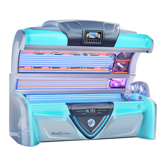
- Page 1 (devices with touch screen) TANNING DEVICE TANNING DEVICE ASSEMBLY INSTRUCTIONS & MENU SETTINGS...
- Page 3 Technical equipment and versions of the devices are in accordance with the legal prescriptions of the respective country of destination. Export to the European Union of the KBL products, listed in this guide, or operation of the systems in these countries, are not permitted. KBL does not accept any manufacturers liability in case this direction is not adhered to.
-
Page 4: Table Of Contents
Contents 1. General information .......... 5 6.7 Connecting the channel selection ....45 1.1 About these instructions ....... 5 6.8 Connecting the external timer ..... 45 1.2 Safety signs ........... 5 6.9 aquaCool and Aroma connections ....46 1.3 Signal words ..........5 6.10 Initial operation .......... -
Page 5: General Information
1. General information 1.1 About these instructions This symbol indicates that damages This manual is intended for use by may occur at the tanning device, at the • studio operator. material or at the environment. • qualified, trained and authorized service techni- Danger due to leakages. -
Page 6: Transport
1.4 Transport WARNING Overturning load Danger of being crushed by heavy parts of the equipment. • Keep the safety distance to the trans- port machine. • Do not walk under the load. • Wear safety shoes. 1.4.1 TRANSPORT BY FORKLIFT TRUCK During transport the tanning device may be damaged when using forklift forks that are too short. -
Page 7: Safety Notes
2. Safety notes 2.1 General safety notes Before carrying out any work, the tanning device must be disconnected from the mains voltage. • Follow all instructions given in this manual and all other documents enclosed with the tanning device. DANGER In addition, observe all relevant statutory provi- Live parts sions and regulations, also those applicable in the... -
Page 8: Installation Site & Dimensions
Installation site & Dimensions 3.2 Distances In dry rooms (booths) with sufficient airing. • Even floor with sufficient load capacity • Relative humidity: ≤ 70 % • Room temperature ≤ 30 C (86 • Minimal room height 2400 mm (≈94,5 inches) •... -
Page 9: Disassembly
4. Disassembly 4.1 Tools and aids The disassembly and assembly steps of the tanning device are described in the chapters that follow. The tools and hardware required to correctly and Cutter knife safely perform these steps are shown at the begin- ISK screw driver (SW 4 / 60 mm) ning of each chapter. -
Page 10: Preparation
4.2.2 OPEN THE BED 4.3 Preparation 4.3.1 OPEN CANOPY PANE Attention Prevent the canopy pane from falling down when opening it! • Open the middle pane lock at last Ⓑ. Attention The bed and the bed pane can be dam- aged when it is opened incorrectly. - Page 11 4.3.3 FIX CONTROL PANEL CABLE, 4.3.5 OPEN BED PANE by clamping it behind the air nozzle as seen in the • Hold the bed pane in the middle of the front edge ⑤ and lift it. figure. • Lock it in place using the lateral snap braces ⑥. ⑤...
-
Page 12: Remove Bed Pane
4.4 Remove bed pane 4.4.1 LOOSEN BED PANE • Lift the bed pane in the middle ⑧ (second person) and unscrew the bottom bolt ⑨ (M6x8) of the left and right snap brace. Remove the bolt and the ⑪ washer ⑩. ⑧... -
Page 13: Remove Front Panel
• Move the complete bed pane slightly to the left so • Transport the bed pane to the installation site and that the right pin is also free. set it down safely on protective padding. 4.5 Remove front panel 4.5.1 INSTALL CANOPY PANE (TEMPORARILY) Safety measures to protect the tube 4.4.3 LIFT OUT BED PANE section of the canopy. - Page 14 4.5.5 DISCONNECT CAN-BLUETOOTH-AUDIO 4.5.6 LOOSEN FRONT PANEL MODUL • Two screws (M6x12) per side. • Disconnect all cables from the module. • Pull through the opening in the front panel. α • In 7900/8000 devices the cable of the decorative lighting of the center plate (D14) must in addition be dis- connected before the front panel is lifted out.
-
Page 15: Remove Bottom Components
4.5.7 LIFT OUT FRONT PANEL • Unscrew bottom fastener of the aquaCool unit. • Lift out front panel (second person required). • Unscrew the cover of the aquaCool canister and remove the canister. • Transport it to the installation site and set it down safely on protective padding. - Page 16 4.6.2 REMOVE AQUACOOL UNIT 4.6.3 REMOVE ELECTRONIC BOX • Loosen the cable harness (D10/D11) on the left • Disconnect all connectors routed in the rear wall on foot and pull it out of the opening. the left-hand side of the electronic box. •...
- Page 17 • Disconnect the cable for the channel selection in • Disconnect the mains cable on the bottom of the the electronics tray. electronic box. • Follow the connection diagram during installation! 4 3 1 2 6 5 • Follow the connection diagram during installation! ->...
- Page 18 • Disconnect the main fan plug (X16). • Disconnect plug connectors on the right-hand side. Position: On the left-hand side of the fan in the rear • X21 (air conditioner) area. • X25 (right-hand radial fan) • Disconnect cable XM (power supply unit / bass box). •...
-
Page 19: Remove The Bed
• Place the loose cable harness together with the 4.6.4 REMOVE AIR CONDITIONER condensate pump ⑮ and the condensate canister • Pull the air conditioner out of the connection cone, ⑭ in the electronic box. lift it out towards the front and transport together with the condensate tray to the installation site. - Page 20 4.7.3 LOOSEN THE BED • Follow the connection diagram on the • Slide the bed pane pilot pin ⑫ approximately 30cm rear wall during installation! to the right. ⑫ 4.7.2 REMOVE BED DAMPERS • Lift the bed in the middle (second person) and remove the top locking pin of the two dampers ⑫...
- Page 21 4.7.4 LIFT OUT THE BED • Lift the bed on the front edge on both sides at the same time (second person) about 5–10 cm and pull out towards the front. - Transport the to the installation site and put it down on the waiting padding.
-
Page 22: Remove Canopy
4.8 Remove canopy 4.8.1 REMOVE EXTERNAL CONTROL PANEL STANDARD CONTROL PANEL • Press the control panel down lightly with your fin- gers Ⓐ and then tilt the upper edge forward Ⓑ. Ⓐ Ⓐ Ⓑ • Disconnect connectors 2x CAN, 1x USB and remove the control panel. - Page 23 4.8.2 REMOVE FRONT PLASTIC CLADDING • Open the canopy and evenly press the front edge • Disconnect the two plug connectors D1/D2 in the of the cladding on both sides a little bit upwards. control panel tray. • Loosen three M6x16 countersunk screws each on •...
- Page 24 4.8.3 RELEASE TENSION ON THE CANOPY • Take both steel ropes of the canopy lifting mecha- nism off the guide pulleys. CAUTION • Components are under spring tension Risk of injury by the canopy dropping down when releasing the tension of the canopy lifting mechanism.
- Page 25 • Have two people to lift the cladding out of the rear • Loosen the four knurled-head screws and fold the guide slot. sealing rubber onto the rear wall. • Then lift it off the two bolts of the knurled-head α...
- Page 26 4.8.6 LOOSEN THE CANOPY • Push the canopy brake cylinder together. • Stick both ropes (left/right) of the canopy lifting mechanism for safety through the bracket of the side canopy end caps. 4.8.7 LIFT OFF THE CANOPY • Place two trolleys in position in front of the pallet. •...
- Page 27 • Careful set it down on the two trolleys on the rear Be careful when transporting and setting aluminum profile. Attention -> keep the distance to the canopy down. the ground. • Distance to ground at least 30cm. The end stops may not touch the ground. •...
-
Page 28: Remove The Feet
4.9 Remove the feet 4.9.2 REMOVE RIGHT FOOT OF THE DEVICE • Loosen wiring harness. • Loosen inside screws 6 x (PH2) • Loosen outside screws 2 x M8. 4.9.1 REMOVE LEFT FOOT OF THE DEVICE • Loosen inside screws 4 x (PH2) •... - Page 29 4.10.2 LOOSEN SAFETY MECHANISMS The rear wall can be lifted onto the trol- • Remove rear wall locking screws (PH2) one each leys by 2 people. When the rear wall has side (left/right). to be transported over a longer distance and/or up stairs, it must be done by at least 3 people.
-
Page 30: Assembly
5. Assembly 5.2.2 INSTALL BASS BOX IN THE RIGHT-HAND FOOT OF THE TANNING DEVICE Assembly basically follows the disas- INSTALL THE BASS BOX sembly steps in reverse order. • Unscrew cover plate (8x 4,2x9,5 - PH2). Deviations are explained in this chapter. When installing illuminated decorative parts, make sure that the connection cable of the LED strips do not form... - Page 31 POWER SUPPLY - PREPARING FOR OPERATION CONNECTING CABLES • Disconnect the power supply from the transport • Pull the cables through the opening in the right position (1x PH2) foot part. • X24 (shoulder tanner) • D12/D13 decorative lighting shoulder/foot •...
-
Page 32: Assemble The Feet Of The Tanning Device
• Attach cover plate. 5.3.2 SCREW ON THE FEET Similar to disassembling steps (4.9). • When attaching the screw, the foot must be lifted slightly at the rear. 5.3 Assemble the feet of the tanning device 5.3.1 FASTEN SPACER PLATES 5.4 Install canopy ⑯... - Page 33 5.4.4 INSTALL REAR PLASTIC CLADDING 5.4.6 FASTEN EXHAUST AIR VENT Similar to disassembling step (4.8.4). • Fasten exhaust air vent (4x M6 x 16 - PH2). Remove all protective film! 5.4.5 FASTEN GUIDE PLATES • The two guide plates are fastened outside to a box with attachments.
-
Page 34: Install Bottom Components
5.4.9 PUT ON LOOSELY - FRONT PLASTIC 5.5 Install bottom components CLADDING Similar to disassembling step (4.8.2). 5.4.10 ESTABLISH CONNECTIONS D1/D2 5.5.1 INSTALL AND ALIGN AIR CONDITIONER Similar to disassembling step (4.8.2). Similar to disassembling step (4.6.4). 5.4.11 INSTALL EXTERNAL CONTROL PANEL The air conditioning unit should have Similar to disassembling step (4.8.1). -
Page 35: Install The Bed
5.5.5 INSTALL THE AROMA DOSE TIN 5.6 Install the bed • Take out aroma tin ㉒ from the accessory box and install in the aquaCool unit. - Release retaining clip. - Insert aroma tin. 5.6.1 REMOVE CANOPY PANE - Lock retaining clip. •... -
Page 36: Install Bed Pane
5.8 Install bed pane 5.9 Attach canopy end caps Remove protective film on the bottom! 5.9.1 OPEN CANOPY PANE • The film on the top stays on until after 5.9.2 FASTEN CANOPY END CAPS aquaCool initialisation. • Unpack both canopy end caps (left/right) from 5.8.1 INSTALL BED PANE the box. -
Page 37: Fine Adjustment Of The Canopy Drive
5.10 Fine adjustment of the 5.11 Attach hinge caps canopy drive 5.11.1 CLOSE THE BED Attention 5.11.2 OPEN THE SIDE PANE Adjust the canopy drive only at the lower springs! 5.11.3 FASTEN HINGE CAPS • Unpack both hinge caps (left/right) from the box. -
Page 38: Attach Left Shoulder Piece
5.12.2 FASTEN SHOULDER TANNER / • Connect the audio cables. SHOULDER PIECE Shoulder tanners or shoulder piece: • Carefully insert into the gap between bed and rear wall. Attention Do not tilt! Component can be damaged. 5.13 Attach left shoulder piece •... -
Page 39: Install Side Plates
Adjustment options: • Unscrew clamping screw. • Right/left offset – to be done via the front plate. Grab hold of the top of the plate and using physical strength carefully jerk it in the required direction to move it sideways. •... -
Page 40: Install Foot Cladding
5.16 Install foot cladding On both sides (left/right): • Connect decorative lighting plug on foot Ⓒ. • Slide foot cladding from the top over the retain- ing lugs. Ⓒ Attention Do not pinch cables! α α A s s e m b l y I n s t r u c t i o n s | 7000 /8000 touch... -
Page 41: Connections & Initial Operation
6. Connections & Initial operation 6.1 Class I ME equipment on the site side. This means that for full separation each pole must have a contact gap according to the WARNING conditions of the overvoltage category III. The device Risk of electric shock shall be capable of being locked in the off-position To avoid the risk of electric shock, this and shall comply with IEC 60447. -
Page 42: Connecting An External Audio Source
If you decide for a connection to a 100 V audio can only be conducted in the service menu. system, you will need a transformer (KBL no.: 9100 0170 00) for the transmission of the audio signal. This connection must be made by qualified, trained and authorized service technicians. -
Page 43: Bluetooth Connection
The a short time. audio signal is switched over automatically. • Among the available tanning devices choose “KBL Sound”. In the service menu, a trailing number (01, 02, 03, ...) can be added to tanning device name. -
Page 44: Connecting The Channel Selection
COMPATIBILITY OF BLUETOOTH DEVICES KBL GmbH attaches great importance to hardware compatibility. Due to the large number of manufac- turers, KBL can not guarantee a 100 % compatibility. In rare cases, it may happen that a bluetooth con- nection can not be established. -
Page 45: Connecting The External Timer
6.8 Connecting the external • Attach the connectors to the T-Max board and housing (ground). timer Pass both, the connector cable of the T-Max timer and the leads of the tanning device, from the main port through the cable entry in the rear wall to the T-Max Box. -
Page 46: Aquacool And Aroma Connections
6.9 aquaCool and Aroma 6.10 Initial operation connections • Insert batteries in colorMotion remote control unit. • Turn on the supply voltage. AQUACOOL • Start the aquaCool initialisation before tanning for The aquaCool box is equipped with a liquid- ① the first time. -
Page 47: Service Mode
7. Service mode When the tanning device is in service mode, you can make the presettings for operation in tanning mode, and you can have values concerning the operation of the tanning device displayed. 7.1 Starting the service menu (touch screen) Press and hold the ICS logo until the ser- vice menu start window appears. -
Page 48: Service Menu - Start Window
7.2 Service menu - Start window In standby mode, the service level is accessed by entering the factory CODE 1 „00000“, the supplied CODE 2 or individually defined CODES. SERVICE MENU There is one additional condition that must be fulfilled: EXIT •... -
Page 49: Service Menu - Basics
7.3 Service menu - Basics The service menu is divided into the main menu and back exit the function menu. Main menu If you choose a menu item, e.g. “AUDIO”, you will get access to all functions related to this item. Language MAIN MENU Date / Time... - Page 50 SERVICE MENU - BASIC OPERATION Example: Switch functions on or off Touch the desired main group function bar in the aroma main menu. The current selected function bar is highlighted. back exit Main menu Language Date / Time STORE, BACK & EXIT Timer decorative Save your settings by pressing the light...
-
Page 51: Servicemenu - Overview
7.4 Servicemenu - Overview KBL-7 ① LANGUAGE AQUACOOL SETTINGS DATE / TIME ㊱ aquaCool ② Date ㊲ Spray time ③ Time ㊳ Cycle time ④ TIMER DECORATIVE LIGHT TEST & INIT ㊴ Testcycle ⑤ MAXIMUM TANNING TIME ㊵ Endurance testcycle ㊶... -
Page 52: Service Codes
7.5 Service codes 7.6 Service menu - Menu items SERVICE-CODE LEVEL 1 • In order to avoid operating errors, Access to the service menu start window is pro- read through the service menu - tected by CODE 1. When delivered, this CODE is basics at the beginning of this sec- 00000. - Page 53 ④ A-ON A-OFF Timer decorative light The menu item Timer decorative light offers you two switching cycles (A and B) for each day of the week. [24h] [24h] NOTE - SWITCHING CYCLES Using the setting „monday-sunday“, the switching Entering switching times for the cycle will be the same for each day of the week.
- Page 54 Tubes ⑦ Preselection Tubes Reset Under the menu item Preselection you can make the initial settings for the tanning device. The functions must be available and activated in this service menu! [hrs.] Hold for 2 sec to activate Displays the total operating hours of the tubes and Basic settings - 1 includes a reset function and set function to set the ⑩...
- Page 55 ⑰ Basic settings - 2 MP3 - external / ⑬ Bluetooth Aircondition on / off Activates and deactivates the external MP3 and bluetooth on / off signal. Determines the initial setting (bluetooth) of the air-conditioning system. Factory setting: on Factory setting: on ⑱...
- Page 56 ㉑ Music non-stop BCD - / Pulse - Code ㉔ Music non-stop pulsecode on / off pulsecode If this function is active, music is played nonstop, i.e. also out of tanning Allows for the change-over between pulse-code sessions. and BCD-code mode with the Studio music sig- nal pending and deactivates the external-channel Factory setting: off selection.
- Page 57 ㉘ Equalizer studio Max. volume ㉜ 5 .. . 9 Treble High Bass Low Bass Presetting the maximum adjustable sound level. [5-9] Limits the maximum adjustable sound level in the tanning mode. [dB] [dB] [dB] Factory setting: 9 -14 .. . +14 dB -14 ..
- Page 58 ㊲ Spray time Bluetooth Grundeinstellungen 2 .. . 6 sec. ㉞ Determines the duration of Name the aquaCool spraying time. [sec.] megaSun: 1 megaSun: 1 .. . 99 Factory setting: 6 sec. ㊳ Cycle time 1 .. . 5 min. To fit your Studio environment (multiple units) differ- Defines the aquaCool and ent numbers can be added to the bluetooth device...
- Page 59 ㊶ Basic settings - 2 Initialization ㊺ Aroma cabin automatic Starts the aquaCool Interval initialization process. Door contact Hold for 2 sec to activate A spraying cycle of 90 seconds is started to bleed the system before commissioning, after a repair The cabinet scent release can be set at intervals, operation or after a canister replacement.
- Page 60 ㊽ Aroma timer The menu item Aroma offers you a switching cycle for each day of the week. [24h] [24h] NOTE - SWITCHING CYCLES Using the setting „monday-sunday“, the switching Entering switching times for the cycle will be the same for each day of the week. aroma timer.
- Page 61 Enter your individual Service - Code Level 1 These settings must only be made by After entering the service code a “save” trained and qualified personnel, authorised button appears. Press this button to accept by KBL! the new CODE 1! Factory setting: 1 Service-Code Level 2 Service...
- Page 62 Software Service with tanning Software Troubleshooting mode. KBL 7 Touch Variante Hybrid Hold for 2 sec to activate Erster Upload 2.3.2017 dd.mm.yy Letzter Upload 19.11.2017 dd.mm.yy The service mode is switched on for 10 minutes. The mains voltage is connected. Error notifica- Displays the current software type and variant and tions are ignored, tanning can be started.
- Page 63 For details, tap. For more information on EventID‘s, please These settings must only be made by refer to chapter System messages . trained and qualified personnel, authorised by KBL. Touchscreen test Touchsceen Screen test Temperature test Hold for 2 sec to activate...
- Page 64 Remarks α α A s s e m b l y I n s t r u c t i o n s | 7000 /8000 touch...
- Page 65 Remarks α α A s s e m b l y I n s t r u c t i o n s | 7000 /8000 touch...
- Page 66 Remarks α α A s s e m b l y I n s t r u c t i o n s | 7000 /8000 touch...
- Page 68 Ringstraße 24-26 56307 Dernbach / Germany fon: +49 (0) 26 89.94 26-0 fax: +49 (0) 26 89.94 26-66...
Need help?
Do you have a question about the 8000a and is the answer not in the manual?
Questions and answers