GILES FSH-6 Operation & Service Manual
Hide thumbs
Also See for FSH-6:
- Operation & service manual (66 pages) ,
- Operation & service manual (68 pages) ,
- Operation & service manual (68 pages)
Table of Contents
Advertisement
Quick Links
Operations & Service Manual
FSH−6 Hood
ISO 90012015 Registered • Committed to Quality
2750 Gunter Park Drive West • Montgomery, AL 36109 USA
Toll Free: 800.554.4537
Other: 334.272.1457
(USA & Canada Only)
Fax: 334.239.4117 • Website: www.gfse.com • Email: services@gfse.com
Printed in USA, Form 64898 (Rel. Date: Jul.1999, Rev. Date: Jul.2022. Rev. M)
Advertisement
Table of Contents

Related Manuals for GILES FSH-6


Summary of Contents for GILES FSH-6
- Page 1 Operations & Service Manual FSH−6 Hood ISO 90012015 Registered • Committed to Quality 2750 Gunter Park Drive West • Montgomery, AL 36109 USA Toll Free: 800.554.4537 Other: 334.272.1457 (USA & Canada Only) Fax: 334.239.4117 • Website: www.gfse.com • Email: services@gfse.com Printed in USA, Form 64898 (Rel.
- Page 3 • During the Limited Warranty period, Giles will replace or recondition, at its factory, any part or parts of this unit which Giles inspectors judge defective, provided the unit has been properly installed, subjected to nor...
-
Page 5: Table Of Contents
Table Of Contents Model: FSH−6 Safety ..............v Safety Overview . - Page 6 Model: FSH−6 Table Of Contents Operation & Filter Maintenance........25 4.01 Starting the Hood .
-
Page 7: Safety
The information contained in this manual has been prepared to describe the proper procedures for safely installing, operating and maintaining the Giles Ventless Recirculating Hood. Throughout the manual, safety precautions are identified by hazard alert symbols and the key words DANGER, WARNING &... -
Page 8: Specific Safety Precautions
Model: FSH−6 Safety Specific Safety Precautions: For your safety, please observe the following precautions when operating or servicing this GILES food service equipment. Adhering to the following important safety information will help to prevent personal injury and/or damage to the equipment. - Page 9 Safety Model: FSH−6 Specific Safety Precautions: • Exercise care when removing wooden crate framework and the unit from shipping pallet. The hood is very heavy; extreme precaution must be exercised when handling and assembling the stand and lifting the hood for mounting atop the stand.
- Page 10 Simple Green® Crystal Foaming Spray Cleaner/Degreaser. ▪ GILES assumes no responsibility with regard to code compliance during installation or the use of ventless recirculating ventilation equipment. The customer shall be responsible for obtaining all of the necessary approvals from Authorities Having Jurisdiction (AHJ) before installation and use of this equipment.
-
Page 11: Introduction
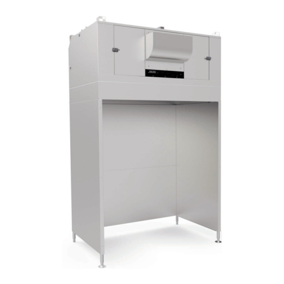
Model: FSH−6 1. Introduction THANK YOU for purchasing the Giles FSH‐6 Ventless Recirculating Hood w/72” Floor Stand, manufactured by Giles Enterprises, Inc., Montgomery, Alabama (USA), hereafter referred to as "GILES". Giles ventless technology is the result of extensive engineering, research and development. Every unit is thoroughly inspected and tested prior to shipment to ensure that it will operate flawlessly when installed. -
Page 12: Specifications
Introduction Model: FSH−6 1.04 Specifications 1.04.1 Overall Dimensions Code Dimension 729/16 [1843] 687/16 [1738] 733/4 [1873] 72 [1829] 1173/16 [2977] INCHES [mm]... -
Page 13: Agency Certifications
Introduction Model: FSH−6 1.04.2 Agency Certifications 1.04.3 Weights Hood Crated Weight Uncrated Weight (approx) FSH6 & Stand 925 lbs [420 kg] 725 lbs [329 kg]... -
Page 14: Installation
Location • DO NOT ALTER, ADD ATTACHMENTS OR OTHERWISE MODIFY THIS EQUIPMENT. • Failure to comply with installation requirements as specified by the Giles Hood Approval Letter will void the factory warranty. 1. A minimum clearance of 14” (355.6 mm) must be maintained between the top of the hood exhaust outlet and the ceiling, or other overhead obstruction. -
Page 15: Unpacking
... not included with hood purchase. IMPORTANT! The hood stand is the only installation method now approved by Giles ... the former “ceiling suspended” installation method is no longer an acceptable option. Attempting to install the hood in such a way can void the factory warranty. - Page 16 Model: FSH−6 Installation 2.03 Stand & Hood Assembly − continued TRIM CAP TRIM CAP Install upper back panel. TABS ON CHANNELS SHOULD FIT INTO SLOTS ALONG BOTTOM EDGE OF STAND SIDES. ADJUST LEGS TO LEVEL HOOD. Use extreme care when mounting hood onto stand, or when moving ANCHOR LEGS TO FLOOR, AS the assembled hood stand into a final position.
-
Page 17: Cooking Appliance Limitations & Clearances
Installation Model: FSH−6 2.04 Cooking Appliance Limitations & Clearances IMPORTANT! The following clearance diagrams in this section depict “ceiling suspended” hoods over various appliances. Ceiling mounting is no longer an acceptable installation method. The “side clearance minimum” dimensions shown in these illustrations will not apply for the freestanding hood versions ... -
Page 18: Oven Limitations
Model: FSH−6 Installation 2.04.3 Oven Limitations (Electrically Heated Appliances ONLY) Max. kW Input Hood Max. Temp. (Total) FSH6 500° 55 kW 2.04.4 Oven Clearances 68 max [1727.2] Floor Stand Inches [mm]... -
Page 19: Griddle Limitations
Installation Model: FSH−6 2.04.5 Griddle Limitations (Electrically Heated Appliances ONLY) Hood Max. Temp. Max. kW Input Max Cooking Surface FSH6 400° 60 x 26 2.04.6 Griddle Clearances * Sidetoside overhang clearances DO NOT apply for the floor stand installation. * 0” w/Floor * 0”... -
Page 20: Range Constraints
Model: FSH−6 Installation 2.04.7 Range Limitations (Electrically Heated Appliances ONLY) Hood Max. Temp. Max. kW Input Max Burners FSH6 400° 25 kW 2.04.8 Range Clearances * Sidetoside overhang clearances DO NOT apply for the floor stand installation. 5” MIN [381] * 0”... -
Page 21: Electrical Specifications Hood Only
Installation Model: FSH−6 2.05 Electrical Specifications − Hood ONLY • Food service equipment must be properly grounded in accordance with local code, or in the absence of local code, with the National Electrical Code, ANSI/NFPA 70. Improper grounding may result in electrical shock to users. -
Page 22: Routing Power Conduit & Wiring
Model: FSH−6 Installation 2.05.2 Routing Power Conduit & Wiring This diagram shows a typical conduit and wiring setup for connecting hood and appliance power. See Section 2.05.3, Hood & Appliance Interlock Diagram for details on setting up the interlock circuit for the underHood appliances. -
Page 23: Fire Suppression System Installation
2.06 Fire Suppression System Installation Giles ventless hoods must be protected by the Ansul® R‐102 Restaurant Fire Suppression System in accordance with the hood listing. Hood includes factoryinstalled piping, plenum discharge nozzles (appliance drop‐downs & nozzles not included), detector link brackets, and cable conduit. Piping and conduit are stubbed out on either side of hood, ready for connection of the fire suppression system. -
Page 24: Fire Suppression Detector Links & Location
Model: FSH−6 Installation 2.06.2 Fire Suppression Detector Links & Location All fusible detector links shall be supplied & installed by an authorized Ansul® technician. Fire Damper 285°F (Factory installed) 165°F (Ansul #56811) 165°F (Ansul #56811) 165°F (Ansul #56811) 2.06.3 Appliance Nozzles Nozzles centered over cooking surface(s) Appliance nozzle, (2) minimum. -
Page 25: Fire Extinguisher Nozzle Locations
Installation Model: FSH−6 2.06.4 Fire Extinguisher Nozzle Locations Plenum Nozzle 1W flow (Factory installed) Plenum Nozzle 1/2N flow (Factory installed) Appliance nozzle, (2) minimum, Plenum Nozzle 1/2N flow sized & installed by authorized Ansul® (Factory installed) service technician (Customer supplied) - Page 26 Model: FSH−6 Installation...
-
Page 27: Overview
Overview Model: FSH−6 3. Overview This section provides a brief overview of the hood’s components, functions, and accessories. Please review carefully before proceeding. Hood Exhaust Duct w/ Fire Damper Left Filter Right Filter Chamber Chamber Section 3.02 Section 3.02 Control Panel Section 3.01. -
Page 28: Control Panel
Model: FSH−6 Overview 3.01 Control Panel... - Page 29 Overview Model: FSH−6 3.01 Control Panel Item Description Function Light Switch Controls underhood lighting. Press and momentarily hold the top [START] portion of switch to start hood and provide power to cooking appliances. Release & switch remains POWER Switch in the [ON] position (center). To turn hood OFF & shutdown power to “PUSHTOSTART”...
-
Page 30: Filter Chamber & Exhaust
Model: FSH−6 Overview 3.02 Filter Chamber & Exhaust * Not shown... - Page 31 Overview Model: FSH−6 3.02 Filter Chamber & Exhaust Item Description Function Provides access to filter chamber & hood filters (prefilter, E.A.C. Hood Filter Door (2) cell & charcoal). Both doors must be closed and latched before the hood will operate. The first stage of ventless air cleaning system.
-
Page 32: Accessories Items Included W/Hood
Model: FSH−6 Overview 3.03 Accessory Items Included w/Hood Part Description/Part Number Function Baffle Filter (2) Captures largest grease P/N 42300 particulate in cooking vapors. Removes additional greaseladen PreFilter (2) vapor and moisture from the air. P/N 91707 Singleuse only, disposable, must be replaced. - Page 33 GILES recommended collector cell (2) Sample Cans cleaner. Foaming Crystal Spray on foaming degreaser for Cleaner/Degreaser cleaning EAC collector cells. P/N 41510 Cleaner is readily available from 12‐count Case Giles and online distributors, as NSF approved well as many nationwide retail outlets.
- Page 34 Model: FSH−6 Overview...
-
Page 35: Operation & Filter Maintenance
Operation & Filter Maintenance Model: FSH−6 4. Operation & Filter Maintenance 4.01 Starting the Hood Be sure that all filters are in place and access doors are closed and latched securely before attempting to start the hood. The hood will NOT power‐up if either access door is open, or ajar. To Start the Hood: 1. -
Page 36: Baffle Filter Removal
Model: FSH−6 Operation & Filter Maintenance 4.02.2 Baffle Filter Removal ① Turn OFF power. Baffle filters are located on underside of hood, directly above the appliances. ② ④ ③... -
Page 37: Baffle Filter Installation
Operation & Filter Maintenance Model: FSH−6 4.02.3 Baffle Filter Installation ② ① Front View Position filters w/ ③ baffles in the vertical position Switch arm must be actuated by the filter as shown... -
Page 38: Prefilter Removal
Model: FSH−6 Operation & Filter Maintenance 4.02.4 Pre−Filter Removal ① Turn OFF power. Prefilters are located inside the filter chamber in the outermost position on each side. PreFilters Door open ② Front View... -
Page 39: Prefilter Installation
Operation & Filter Maintenance Model: FSH−6 4.02.5 Pre−Filter Installation PreFilter Paper side (to outside) Paper side (to outside) PreFilter Door open Metal mesh side (facing toward middle) Roller on switch must be actuated by the filter frame when installed. Front View Close Door NOTE: When filters are changed, always record the installation date of the new filter in the space provided on the label. -
Page 40: Filter Cell Removal
Model: FSH−6 Operation & Filter Maintenance 4.02.6 E.A.C. Collector Cell Removal ① Turn OFF power. Collector cells are located inside the filter chamber in the middle position on each side. Door open Left E.A.C. Cell Right E.A.C. Cell ② Folding handle ... use this handle to avoid damaging cell... -
Page 41: Filter Cell Installation
Operation & Filter Maintenance Model: FSH−6 4.02.7 E.A.C. Collector Cell Installation Filter contact Hood contact plate (UP) plate (inside top) Airflow arrow, on cell front. [Left] [Right] E.A.C. Alignment Pin Folding handle ... use this handle to avoid damaging cell Contact strips on cell must make good connection with contact plates inside... -
Page 42: Charcoal Filter Removal
Model: FSH−6 Operation & Filter Maintenance 4.02.8 Charcoal Filter Removal ① Turn OFF power. Charcoal filters are located inside the filter chamber in the innermost position on each side. Charcoal Filter Door open ② Front View... -
Page 43: Charcoal Filter Installation
Operation & Filter Maintenance Model: FSH−6 4.02.9 Charcoal Filter Installation Charcoal Filter Door open Blue fiberfill side faces middle Front View Roller on switch must be actuated by filter frame when installed. Close Door... -
Page 44: Hood Filter Alarms
Model: FSH−6 Operation & Filter Maintenance 4.03 Hood Filter Alarms 4.03.1 Baffle, Pre−Filter or Charcoal Filter Missing If a baffle, fiber, or charcoal filter is not in place, or possibly not positioned correctly, the red [CHARCOAL OR BAFFLE FILTER MISSING] light will turn ON. Power to cooking appliances under the hood is turned OFF until the condition is corrected. -
Page 45: Filter Status & Alarm
Operation & Filter Maintenance Model: FSH−6 4.03.3 E.A.C. Filter Status & Alarm Two LED indicator light clusters on the control panel show the operational status of the electronic air cleaner (EAC) system on each side of the hood. [ON] Indicates that the EAC collector cell is installed, powered and operating. -
Page 46: Baffle Filter Cleaning
& easy using this convenient readytouse cleaner. A complimentary sample is supplied with new equipment and it is availabel from Giles, item #41510 (12‐count case), as well as multiple retail outlets. When used as directed, a case of the cleaner should lasr approximately 4 to 5 weeks, depending on equipment model and cleaning protocols. - Page 47 IMPORTANT! ONLY Simple Green® Crystal Foaming Cleaner/Degreaser is recommended by GILES for cleaning cells in this manner. Other cleaners can contain corrosive ingredients that may damage the metal and cause the cell to fail or not perform properly. Such damages are not covered by the factory warranty.
-
Page 48: Collector Cell Cleaning Timer
1. This method requires a suitable, leakproof container, such as a tall trash bin, recycle bin, plastic tote, or the GILES soak tank*. Container must be large enough to hold the cell along with enough degreasing solution to submerge it completely for soaking, regardless of orientation. -
Page 49: Prefilter Maintenance
Typically, prefilters should be replaced weekly (see Sections 4.02.4 & 4.02.5). They CANNOT be cleaned and are not intended for longterm use. Use GILES replacement Item No. 91707. Write the replacement date on new filter. IMPORTANT: Failure to use Giles OEM parts and OEM replacement filters may void the factory warranty. -
Page 50: Charcoal Filter Maintenance
CANNOT be cleaned and reused. Typical replacement cycle is every 30 to 40 days, depending on usage. Use GILES replacement Item No. 32056. Write the replacement date on new filter. IMPORTANT: Failure to use Giles OEM parts and OEM replacement filters may void the factory warranty. -
Page 51: Hood Cleaning And Maintenance
Use the Maintenance & Service Log to record completion of the test. If problems are detected, contact GILES or an authorized service provider. NOTE: Anytime a filter access door is opened and closed, the hood must be restarted with the power switch. -
Page 52: Quarterly Hood Cleaning
Model: FSH−6 Hood Cleaning & Maintenance 5.02 Quarterly Hood Cleaning DO NOT wash down Hood with a spray hose. DO NOT steam clean or use pressure washing equipment. DO NOT use products containing chlorine or caustic chemicals. DO NOT use abrasive products, steel wool or scouring pads. The factoryrecommended product to use for general cleaning &... -
Page 53: Semiannual Fire Suppression Inspection & Maintenance
Hood Cleaning & Maintenance Model: FSH−6 5.03.1 Semi−Annual Fire Suppression System Inspection & Maintenance Inspection & service for the fire suppression system must be performed by a technician from a qualified Ansul® Distributor/Dealer. As a minimum, field inspection of the system must be conducted semiannually (every 6 months) and shall consist of the following: •... -
Page 54: Maintenance & Service Log
Model: FSH−6 Hood Cleaning & Maintenance 5.04 Inspection & Maintenance Log Check Initial/Date Check Initial/Date RT 1-2-15 1 Door Check Section 5.01 * Must be performed by 2 Baffle Filter Check Section 5.01 an authorized Ansul® 3 EAC Filter Check Section 5.01 Service Agent 4 PreFilter/Charcoal Filter Check... -
Page 55: Troubleshooting
Troubleshooting Model: FSH−6 6. Troubleshooting This section describes basic troubleshooting procedures for the ventless hood. Generally, troubleshooting and repairs should only be performed by trained & qualified service technicians. Troubleshooting by users should be limited to issues and activities that are only operational or procedural. roubleshooting for electrical problems should be performed ONLY by qualified service technicians or professional electricians. - Page 56 Model: FSH−6 Troubleshooting Problem Probable Cause Corrective Action Cooking appliances will not powerup: a. A baffle filter is missing or not Install filter / check positioning. • Hood running properly installed • [ light ON FILTER MISSING] b. A charcoal or prefilter is missing Install filter / check positioning.
-
Page 57: Parts List
Website: Email: Our goal at Giles is to provide the highest possible quality of service and assistance. To help us accomplish this, please have the following information readily available when calling, along with a brief description of the problem being experienced. Please record the unit information in the table below for quick reference. -
Page 58: Component Drawer
Model: FSH−6 Parts List 7.02 Component Drawer... - Page 59 Parts List Model: FSH−6 7.02 Parts List for Component Drawer Item Part No. Qty. Description 21296 EAC POWER SUPPLY, w/DRIVER BOARD, 120V 23776 ALARM & SHUTDOWN MODULE, FILTER SYSTEM 21417 RELAY, POWER SWITCH, 30A/2.5HP, 240V 20390 VACUUM SWITCH, ADJUSTABLE 40877 NYLON FITTING, 90EL, 1/8 MALE NPT, BARB FOR 1/4 I.D.TUBING 40880 NYLON FITTING, 90EL, 1/4 MALE NPT, BARB FOR 1/4 I.D.TUBING...
-
Page 60: Control Panel
Model: FSH−6 Parts List 7.03 Control Panel * Inside Panel, Not Shown... - Page 61 Parts List Model: FSH−6 7.03 Parts List for Control Panel Item Part No. Qty. Description 67143 LABEL, CONTROL PANEL, FSH6 W/TIMER 20398 INDICATOR LIGHT, GREEN, 250V, 0.5W 20399 INDICATOR LIGHT, AMBER, 250V, 0.5W 20420 INDICATOR LIGHT, RED, 250V, 0.5W 20694 PILOT LIGHT, YELLOW, EAC TIMER 20693 PILOT LIGHT, RED, EAC TIMER...
-
Page 62: Hood Filter Chamber
Model: FSH−6 Parts List 7.04 Hood Filter Chamber 10 11* 12* 13* * Not Shown... - Page 63 Parts List Model: FSH−6 7.04 Parts List for Hood Filter Chamber ITEM PART NO. DESCRIPTION 91707 PREFILTER ASSEMBLY, 12 X 20 X 2 98146 E.A.C. FILTER DRIP TRAY 20521 FILTER, EAC 12 X 20, LEFT SIDE ONLY 32056 CHARCOAL FILTER ASSEMBLY 21157 SWITCH, LIMIT, 15A, 250V, BROWN BODY 20520...
-
Page 64: 7.05 Under−Hood Components
Model: FSH−6 Parts List 7.05 Under−Hood Components * Not shown... - Page 65 Parts List Model: FSH−6 7.05 Parts List for Under−Hood Components ITEM PART NO. DESCRIPTION 42300 BAFFLE FILTER, S/S, 20 X 20 32776 DRIP CUP 32102 BAFFLE FILTER SWITCH ASSY. 40625 LIGHT FIXTURE 20395 FLUORESCENT BULB, COATED 98104 CONDUIT COVER...
-
Page 66: Doors, Front Panel & Stand
Model: FSH−6 Parts List 7.05 Doors & Front Panel NOTE: Legs are welded in place ... cannot be replaced. * Not shown... - Page 67 Parts List Model: FSH−6 7.05 Parts List for Doors & Front Panel ITEM PART NO. DESCRIPTION 42827 DOOR LATCH 98036 ACCESS DOOR ASSY, LEFT 46126 FIRE DAMPER, 286°F LINK 98141 FAN COVER (COVER ONLY) 98142 SCREEN, FIRE DAMPER 98037 ACCESS DOOR ASSY, RIGHT 91945 SKIRT, FSH6, 8”, UNIVERSAL 91583...
- Page 68 2750 Gunter Park Drive West • Montgomery, Al 36109 USA Phone: 334.272.1457 • Toll Free: 800.554.4537 • FAX: 334.239.4117 • (USA & Canada Only) Form No. 64898 (Rel. Date: Jul.1999, Rev. Date: Jul.2022, Rev. M) www.gfse.com...
Need help?
Do you have a question about the FSH-6 and is the answer not in the manual?
Questions and answers