Woodward GCP-30 Series Manual
Genset control
Hide thumbs
Also See for GCP-30 Series:
- Manual (179 pages) ,
- Configuration (174 pages) ,
- Installation manual (46 pages)

Subscribe to Our Youtube Channel
Related Manuals for Woodward GCP-30 Series


Summary of Contents for Woodward GCP-30 Series
- Page 1 37238D GCP-30 Series Genset Control Function/Operation Software version 4.3xxx Manual 37238D...
- Page 2 Provides other helpful information that does not fall under the warning or caution categories. Woodward reserves the right to update any portion of this publication at any time. Information provided by Woodward is believed to be correct and reliable. However, Woodward assumes no responsibility unless otherwise expressly undertaken.
-
Page 3: Table Of Contents
Manual 37238D GCP-30 Series - Genset Control Revision History Rev. Date Editor Changes NEW 04-06-02 Release 04-09-23 Minor corrections, functionality from V4.3xxx updated 05-06-15 Appendix Parameters and Set Points added, various minor corrections Description GCP-31 RPQ-SC08 (Rental Package) added 06-01-11... - Page 4 Manual 37238D GCP-30 Series - Genset Control Illustrations And Tables Illustrations Figure 2-1: Front panel GCP-31 ..............................8 Figure 2-2: Front panel GCP-32 ..............................8 Figure 3-1: Direction of power ..............................22 Tables Table 1-1: Manual - Overview..............................5 Table 2-1: Functional overview ............................... 10 Table 2-2: Function –...
-
Page 5: Chapter 1. General Information
Manual 37238D GCP-30 Series - Genset Control Chapter 1. General Information Type English German GCP-31/32 Series GCP-31/32 Packages - Installation 37364 GR37364 GCP-31/32 Packages - Configuration 37365 GR37365 GCP-31/32 - Function/Operation this manual 37238 GR37238 GCP-31/32 - Application 37240 GR37240... - Page 6 Manual 37238D GCP-30 Series - Genset Control The GCP-30 series generator set controllers provide the following functions: • Engine and generator protection • Engine data measurement - ○ including oil pressure and temperature, coolant temperature, battery voltage, speed, service hours, etc.
- Page 7 Manual 37238D GCP-30 Series - Genset Control Intended Use The unit must only be operated according to the guidelines described in this manual. The prerequi- site for a proper and safe operation of the product is correct transportation, storage, and installation as well as careful operation and maintenance.
-
Page 8: Chapter 2. Display And Operating Elements
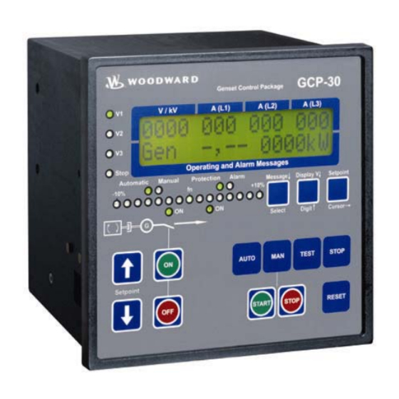
Manual 37238D GCP-30 Series - Genset Control Chapter 2. Display And Operating Elements The pressure-sensitive membrane of the front panel consists of a plastic coating. All keys have been designed as touch-sensitive membrane switch elements. The display is an LC display, comprised of two rows with 16 charac- ters in each row that are indirectly illuminated in red. -
Page 9: Brief Explanation Of The Leds And Buttons
Manual 37238D GCP-30 Series - Genset Control Brief Explanation Of The LEDs and Buttons ≡≡≡≡≡≡≡≡≡≡≡≡≡≡≡≡≡≡≡≡≡≡≡≡≡ LEDs No Description Function Voltage L1 Voltage L2 Voltage L3 Stop "STOP" mode selected -10%..fn..+10% Synchroscope Automatic "AUTOMATIC" mode selected Manual "MANUAL" mode selected Protection... -
Page 10: Functional Overview
Manual 37238D GCP-30 Series - Genset Control Functional Overview ≡≡≡≡≡≡≡≡≡≡≡≡≡≡≡≡≡≡≡≡≡≡≡≡≡ Mode functions RESET STOP AUTO TEST STOP Engine Setpoint MANUAL Mode Start engine Stop engine Close GCB Open GCB Close MCB [GCP-32] Open MCB [GCP-32] Raise set point value Lower set point value... -
Page 11: Leds
Manual 37238D GCP-30 Series - Genset Control LEDs ≡≡≡≡≡≡≡≡≡≡≡≡≡≡≡≡≡≡≡≡≡≡≡≡≡ NOTE The LEDs can be checked via a lamp test. In order to achieve this, the "Setpoint↑" and "Setpoint↓" but- tons must be pressed simultaneously. V1 - V2 - V3 Voltage control Color: green The LEDs "V1", "V2"... - Page 12 Manual 37238D GCP-30 Series - Genset Control Manual "MANUAL" operating mode Color: yellow If the "Manual" LED is illuminated, the "MANUAL" operating mode has been enabled. The circuit breaker control, "START", and "STOP" buttons are enabled. Protection Engine monitoring Color: green If the "Monitoring"...
-
Page 13: Buttons
Manual 37238D GCP-30 Series - Genset Control Buttons ≡≡≡≡≡≡≡≡≡≡≡≡≡≡≡≡≡≡≡≡≡≡≡≡≡ In order to facilitate configuring the control parameters, the buttons are equipped with a "AUTOROLL" function. This permits the user to rapidly advance the display to the next setting, configuration screen, digit, or cursor posi- tion. -
Page 14: Circuit Breaker Operation
Manual 37238D GCP-30 Series - Genset Control Circuit Breaker Operation GCB ON / GCB OFF Close GCG / open GCB Color: green/red Note: These buttons function only if either the MANUAL or TEST operat- ing mode has been enabled. GCB ON ..This function is dependent upon the configured breaker logic. -
Page 15: Operating Mode Selection
Manual 37238D GCP-30 Series - Genset Control Operating Mode Selection AUTO AUTOMATIC operating mode Color: blue The engine is automatically started/stopped and the circuit breakers are automatically actuated. The control inputs "Automatic 1" and "Automatic 2" are used to control the generator output to a configured level while in the "AUTOMATIC"... - Page 16 Manual 37238D GCP-30 Series - Genset Control TEST TEST operating mode Color: blue Pressing the "TEST" button will start the engine and enable engine protec- tive functions. The circuit breakers may be operated manually to conduct load tests. If a mains failure occurs while in the TEST mode, the controller will initiate an emergency and/or sprinkler operation depending on how the control is configured.
-
Page 17: Table 2-2: Function - External Operation Mode Selection
Manual 37238D GCP-30 Series - Genset Control Operation Input Input Function mode blocked STOP AUTOMATIC (terminal 63) (terminal 127) (terminal 128) de-energized nonfunctional nonfunctional The operation mode selection buttons at the front of the GCP are en- abled and are used to change the operational mode (terminals 127/128 have no effect). -
Page 18: Lc Display
Manual 37238D GCP-30 Series - Genset Control LC Display ≡≡≡≡≡≡≡≡≡≡≡≡≡≡≡≡≡≡≡≡≡≡≡≡≡ LC-Display Liquid Crystal Display The LC display shows messages and measured values, depending on the mode or function currently enabled. In the configuration mode, individual parameters are displayed and may be changed. In the AUTOMATIC mode the measured operating values (e.g. -
Page 19: Chapter 3. Display
Manual 37238D GCP-30 Series - Genset Control Chapter 3. Display Measured Values ≡≡≡≡≡≡≡≡≡≡≡≡≡≡≡≡≡≡≡≡≡≡≡≡≡ Top Display Line NOTE By using the "Display V" button will display the different measured voltages. Display in automatic mode, top line: measured values xxxx yyy yyy yyy... -
Page 20: Bottom Display Line
Manual 37238D GCP-30 Series - Genset Control Bottom Display Line NOTE Pressing the "Message↓" button will advance the bottom line of the display. Pressing the "Message↓" button will also advance through any alarm text that may be present. The following screens may be viewed in succession by pressing the "Message↓" button. When the last display screen has been reached, the display returns to the basic screen. - Page 21 Manual 37238D GCP-30 Series - Genset Control Succession Display Description Measured value of the analog inputs (this display depends on the con- --- --- --- --- figuration of the analog input; XPQ Packages only) xxxxxxxxxxxxxxxx Generator reactive power (is calculated via the current of phase L1;...
-
Page 22: Direction Of Power
Manual 37238D GCP-30 Series - Genset Control Direction Of Power If the current transformers for the controller are wired according to the pin diagram shown, the following values are displayed: • Positive generator real power..The generator supplied real power. • Inductive gen. power factor ϕ..The generator supplied inductive re-active power. - Page 23 Manual 37238D GCP-30 Series - Genset Control Inductive: Electrical load whose current waveform lags Capacitive: Electrical load whose current waveform the voltage waveform thus having a lagging power fac- leads the voltage waveform thus having a leading tor. Some inductive loads such as electric motors have power factor.
-
Page 24: Service Display
Manual 37238D GCP-30 Series - Genset Control Service Display ≡≡≡≡≡≡≡≡≡≡≡≡≡≡≡≡≡≡≡≡≡≡≡≡≡ Service display ON/OFF Service display ON ....The service display is enabled and the following three screens are only visible while displayed. The voltages displayed in the screens will differ depend-... -
Page 25: Control Function Messages
Manual 37238D GCP-30 Series - Genset Control Control Function Messages ≡≡≡≡≡≡≡≡≡≡≡≡≡≡≡≡≡≡≡≡≡≡≡≡≡ Synchron. GCB Control function: GCB is synchronizing Synchron. GLS The GCB is synchronizing and will be closed when the synchronous condi- tions are met. Synchronization will be carried out, if generator and busbar voltages are measured. - Page 26 Manual 37238D GCP-30 Series - Genset Control Ignition Control function: Ignition ON (Gas engine) Zündung The ignition is enabled. Governor down Control function: Drive governor down (Diesel engine) Grundstellung The GCP issues a speed lower signal to the speed controller prior to starting the engine.
- Page 27 Manual 37238D GCP-30 Series - Genset Control Sprinkler shutd. Control function: Sprinkler coasting Sprinkler Nachl. The engine will operate without load for 10 minutes following the conclu- sion of a sprinkler operation and the GCP will display this message. Cool down 000s...
-
Page 28: Counters
Manual 37238D GCP-30 Series - Genset Control Counters ≡≡≡≡≡≡≡≡≡≡≡≡≡≡≡≡≡≡≡≡≡≡≡≡≡ Reset Maintenance Call Reset maintenance call ---------------- SERVICE The alarm message to the left is displayed when the configured maintenance inter- val has expired. The maintenance interval is configured when the unit is commis- sioned. -
Page 29: Chapter 4. Alarm Messages
Manual 37238D GCP-30 Series - Genset Control Chapter 4. Alarm Messages Alarm Classes ≡≡≡≡≡≡≡≡≡≡≡≡≡≡≡≡≡≡≡≡≡≡≡≡≡ NOTE If terminal 6 is energized and configured for "Sprinkler operation", alarm classes F2 and F3 are con- verted to alarm class F1. The exception to this is if terminal 34 is energized (terminal 61 if terminal 34 is not available) and overspeed faults. -
Page 30: Acknowledge Alarm Messages
Manual 37238D GCP-30 Series - Genset Control Acknowledge Alarm Messages ≡≡≡≡≡≡≡≡≡≡≡≡≡≡≡≡≡≡≡≡≡≡≡≡≡ WARNING Acknowledging an alarm, which has shut the engine down, while the control is still enabled (i.e. a run signal is still enabled) before to discovering the cause of the fault condition may result in an uninten- tional restart of the engine. -
Page 31: Short Acknowledgement (< 2,5 S)
Manual 37238D GCP-30 Series - Genset Control Short Acknowledgement (< 2,5 s) Methods to perform a short acknowledgement • The "RESET"button is pressed for more than 0.5 seconds but less than 2.5 seconds • Terminal 6 is energized more than 0.5 s seconds but less than 2.5 seconds Result •... -
Page 32: Alarm Messages
Manual 37238D GCP-30 Series - Genset Control Alarm Messages NOTE Pressing the "Message↓" button will advance the bottom line of the display to the next alarm message. Display in automatic mode, second line: Alarms ---------------- yyyyyyyyyyyyyyyy When an alarm is initiated, the corresponding alarm message is displayed in the... - Page 33 Manual 37238D GCP-30 Series - Genset Control NOTE Discrete input – If a discrete input has been configured as alarm input, the alarm and configured text will be displayed when the input is enabled. Analog input – An "!" and the text configured for the analog input screen is displayed as the alarm message when a fault is detected (i.e.
- Page 34 Manual 37238D GCP-30 Series - Genset Control Phase shift Alarm message: Phase shift Alarm class: F0 Phasensprung The monitored measured phase shift has exceeded the limit for the config- ured delay time. Over speed Alarm message: Engine overspeed Alarm class: F3 Überdrehzahl...
- Page 35 Manual 37238D GCP-30 Series - Genset Control Pickup/Gen.Freq Alarm message: Engine speed/frequency mismatch Alarm class: F3 Pickup/Gen.Freq The monitored engine speed (MPU) has deviated by more than 10 Hz from the monitored generator frequency. Interf.err. X1X5 Alarm message: Interface fault X1-X5 Alarm class: F1 Fehl.Schnit.X1X5...
- Page 36 Manual 37238D GCP-30 Series - Genset Control GCBclose failure Alarm message: Malfunction when closing GCB Alarm class: F1 Störung GLS ZU The GCB has attempted to close 5 times and the circuit breaker reply fails to signal that the breaker has closed.
- Page 37 Manual 37238D GCP-30 Series - Genset Control Service Alarm message: Maintenance call Alarm class: F1 Wartung The configured maintenance interval time has expired. ⇒ Also refer to "Reset Maintenance Call" on page 28. Unintended stop Alarm message: Unintended stop Alarm class: F3...
-
Page 38: Appendix A. Code Level Access Permissions
Manual 37238D GCP-30 Series - Genset Control Appendix A. Code Level Access Permissions Code Level 0 or No Code Level Configuration screen Software version Enter code Language first/second Service display Set point in display mode Psetmanual only in "Manual" or "Test" operation mode... - Page 39 Phone +49 (0) 711 789 54-0 • Fax +49 (0) 711 789 54-100 sales-stuttgart@woodward.com Homepage http://www.woodward.com/power Woodward has company-owned plants, subsidiaries, and branches, as well as authorized distributors and other authorized service and sales facilities throughout the world. Complete address/phone/fax/e-mail information for all locations is available on our website (www.woodward.com).
Need help?
Do you have a question about the GCP-30 Series and is the answer not in the manual?
Questions and answers