Table of Contents
Advertisement
Quick Links
Operating Manual
German is the original version.
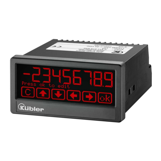
Process indicator with two 16 bit analog inputs, touch screen and graphic display
Product Features:
•
Operating modes for visualization of input 1, input 2 or combinations of inputs (IN1+IN2, IN2-IN2,
IN1xIN2, IN1:IN2)
• Two universal 16 bit analog inputs for -10 ... +10 V / 0 ... 10 V / 0 ... 20 mA / 4 ... 20 mA
• High accuracy reference output 10 V for potentiometers > 1 kOhm
• Bright and high-contrast display with event-dependent color variations
• Emulation of a 7-segment display inclusively icons and units
• Intuitive and easy parameterization by plain text and touchscreen
• 24 V auxiliary output for encoder supply
• Totalization for each input
• Linearization with 24 control points for each input
• Numerous features, e. g. tara, averaging filter, sampling time for each input
• 96 x 48 mm (3.78 x 1.89 inch) norm panel housing and IP65 protection
R60726.0002 - Index 6b
Multifunctional Display 573T
Advertisement
Table of Contents

Related Manuals for Kübler 573T


Summary of Contents for Kübler 573T
- Page 1 Operating Manual R60726.0002 - Index 6b German is the original version. Multifunctional Display 573T Process indicator with two 16 bit analog inputs, touch screen and graphic display Product Features: • Operating modes for visualization of input 1, input 2 or combinations of inputs (IN1+IN2, IN2-IN2, IN1xIN2, IN1:IN2) •...
- Page 2 Version Description 573T_01a /Jan-17 First Version 573T_02a /Feb-17 Second Version 573T_02b /March-17 minor changes and fixes 573T_3a /Oct-17 Index 3, expansion of the scale units 573T_4a /April-18 Extension with IO-Link ➔ in preparation / available on request 573T_5a /June-18 Extension with Modbus 573T_5b /July-18 With Modbus and IO-Link description 573T_6a /April-19...
-
Page 3: Table Of Contents
Table of Contents Safety Instructions and Responsibility ............5 General Safety Instructions ..................5 Use according to the intended purpose ..............5 Installation ......................... 6 Cleaning, Maintenance and Service Notes ..............6 Introduction ....................7 Operation mode ......................7 Function diagram ....................... 8 Electrical Connections .................. - Page 4 Modbus RTU Interface ..................... 46 6.2.1 Parameter setting ..................46 6.2.2 Modbus Communication ................47 6.2.3 Diagnostics ....................48 IO-Link Modul ......................49 6.3.1 Communications data .................. 49 6.3.2 Features ....................... 49 6.3.3 IO-Link interface ................... 49 6.3.4 Parameter data .................... 50 6.3.5 System Commands ..................
-
Page 5: Safety Instructions And Responsibility
Safety Instructions and Responsibility General Safety Instructions This operation manual is a significant component of the unit and includes important rules and hints about the installation, function and usage. Non-observance can result in damage and/or impairment of the functions to the unit or the machine or even in injury to persons using the equipment! Please read the following instructions carefully before operating the device and observe all safety and warning instructions! Keep the manual for later use. -
Page 6: Installation
Installation The device is only allowed to be installed and operated within the permissible temperature range. Please ensure an adequate ventilation and avoid all direct contact between the device and hot or aggressive gases and liquids. Before installation or maintenance, the unit must be disconnected from all voltage- sources. -
Page 7: Introduction
Introduction This series of display unit is suitable for analog signals (-10 … 10V or 0/4 … 20 mA). It is very versatile in use, due to the intuitive handling and the extensive range of functions and options. Operation mode All functions are can be configured in the parameter menu. -
Page 8: Function Diagram
Function diagram R60726.0002 – Index 6b EN - page 8... -
Page 9: Electrical Connections
Electrical Connections The terminal screws should be tightened with a slotted screwdriver (blade width 2 mm). DC Power Supply The unit accepts DC supply from 18 to 30 V at the terminals 1 and 2. The power consumption depends on the level of the supply voltage with approx. 100 mA and the additional current required at the auxiliary voltage output. -
Page 10: Analog Input
Analog Input The reference potential (AGND) for the analog inputs is connected at terminal 5. The unit provides two 16 bit analog inputs at terminal 6 and 7. The characteristics of the analog inputs (voltage input or current input) can be set in the Menu IN 1/IN 2 PROPERTIES. -
Page 11: Control Inputs
Control Inputs The three control inputs at terminal 10, 11 and 12 have HTL PNP characteristics. In the COMMAND MENU the programmable functions for the control inputs can be assigned. Available functions are: reset the display value, display switching, locking the touch screen or release the lock function of the control or relay outputs. -
Page 12: Serial Interface (Option Rs232 Or Rs485)
Serial interface (Option RS232 or RS485) A serial interface (RS232 or RS485) is available at terminal 16, 17 und 18. This interface can be configured in the SERIAL MENU. The serial interface RS232 or RS485 can be used: • for easy setup and commissioning of the units •... -
Page 13: Ac Power Supply (Option)
Wiring of the control-outputs: AC Power supply (Option) The unit accepts AC supply from 115 to 230 V at the terminals 24 and 25. The power consumption depends on the level of the supply voltage with approx. 3VA and the additional current required at the auxiliary voltage output. -
Page 14: Io-Link (Option)
3.11 IO-Link (Option) An interface for connecting to an IO-Link master is available at terminal 34, 35 and 36. The display device (IO-link device) must always be connected to a separate power supply (AC or DC). The display device (IO-link device) can be operated in two ways. •... -
Page 15: Display And Touch Screen
Display and touch screen Screen structure for parametrization The parameter menus and the parameters are described in chapter 5. Start setup procedure: To edit the parameters, press the touchscreen for 3 seconds. Menu selection: Select the parameter menu via arrow buttons and confirm with “OK”. -
Page 16: Screen Structure In Operation
Screen structure in operation The following screens are available during operation. Depending on the device version and the selected operation mode, not all displays will be shown. The source (IN1, IN2, …) for the single channel display and the two channel display are defined in the DISPLAY MENU. -
Page 17: Error Messages
Continuation “Screen structure in operation” Display for quick start for enter preselection values (PRESELECT VALUES) To switch to the next display, press the top of the screen or the “skip” button. This is only possible with Option Analog-, Control- and / or Relay- Output. - Page 18 Continuation “Error messages”: ERROR: MIN. TOP DISPLAY VALUE Top display value of the two-line display is less than -99 999 999 ERROR: MAX. DOWN DISPLAY VALUE Down display value of the two-line display is greater than +99 999 999 ERROR: MIN. DOWN DISPLAY VALUE Down display value of the two-line display is less than -99 999 999 ERROR: MAX.
-
Page 19: Parameter / Overview-Menu Structure
Parameter / Overview-Menu Structure This section provides an overview of the menus and their parameters. The menu names are printed bold and the associated parameters are listed under the menu name. Depending on the device version and the selected operation mode, only the necessary menus / parameters are shown. - Page 20 Menu / Parameter Menu / Parameter IO LINK PROPERTIES PRESELECTION 4 MENU IN1 FACTOR SOURCE 4 IN1 DIVIDER MODE 4 IN1 ADDITIVE VALUE HYSTERESIS 4 IN1 DECIMAL POINT PULSE TIME 4 IN1 SCALE UNITS OUTPUT TARGET 4 IN2 FACTOR OUTPUT POLARITY 4 IN2 DIVIDER OUTPUT LOCK 4 IN2 ADDITIVE VALUE...
-
Page 21: General Menu
General Menu OPERATIONAL MODE This parameter specifies the selected measuring function. 0 SINGLE Single channel mode, only input 1 1 DUAL Dual channel mode, input 1 and input 2 separated 2 IN1 + IN 2 Dual channel mode, sum of input 1 and input 2 3 IN1 –... -
Page 22: In 1 Properties
IN 1 Properties This menu defines the parameter for input 1. CONFIGURATION This parameter defines the configuration of input 1. -10 … 10 V -10 … 10 V 0 … 20 mA 0 … 20 MA 4 … 20 mA 4 …... - Page 23 Continuation “IN 1 Properties”: SAMPLING TIME (S) The configured value corresponds to the sampling interval. This time interval in seconds defines the time between the single samples of the analog signals. This parameter directly affects the response time of the unit. 0.001 Shortest sampling time 0.01...
-
Page 24: In 1 Linearization
IN 1 Linearization The linearization points of input 1 are defined in this menu. This menu is shown only, if the linearization is selected in 1 PROPERTIES. Linearization description and examples are shown in the appendix. P1(X) … P24(X) X-coordinate of the linearization point. This value representing the display value which the unit show in the display without linearization. -
Page 25: In 1 Totalization
IN 1 Totalization The totalization function is defined in this menu. This menu will only be showed, if the totalization is active in Menu IN 1 PROPERTIES. The totalizator depends on the operation mode. See in the following list. Totalization Operation mode INPUT 1 TOTAL INPUT 2 TOTAL... -
Page 26: In 2 Properties
IN 2 Properties This menu defines the parameter for input 2. CONFIGURATION Configuration of input 2, see IN 1 Properties START VALUE Display value of input 2 at 0 V or 0/4 mA, see IN 1 Properties END VALUE Display value of input 2 at +10 V or 20 mA, see IN 1 Properties DECIMAL POINT Position of the decimal point, see IN 1 Properties SCALE UNITS... -
Page 27: In 2 Linearization
IN 2 Linearization The linearization points of input 2 are defined in this menu. P1(X) … P24(X) X-coordinate of the linearization point, see IN 1 Linearization. P1(Y) … P24(Y) Y-coordinate of the linearization point, see IN 1 Linearization. IN 2 Totalization The totalization of input 2 function is defined in this menu. -
Page 28: Linkage Properties
Linkage Properties In this menu the parameters for the linked operation mode are defined. This menu is shown only, if in GENERAL MENU an operation mode (e.g. IN1 – IN2) with link was selected. The parameters in Menu IN 1 PROPERTIES and IN 2 PROPERTIES have to be set, before using a linked operation mode. -
Page 29: Io-Link Properties
IO-Link Properties This menu defines the parameters for the display of the two output process data. This menu is only displayed if the device is equipped with the option (IO-Link Modul). IN1 FACTOR (Multiplication factor) This parameter defines the factor the received value is multiplied with. -99999999 Smallest value Default value... -
Page 30: Preselection Values
5.10 Preselection Values This menu is used to set the preselection values or the switching points. The preselection values / switching points are always referred to the display value. This menu is only available for devices with option Control-, Analog- or Relay-Output. PRESELECTION 1 Preselection / switching point 1 -99999999... - Page 31 Continuation „Preselection 1 Menu“: The totalization depends on the operation mode. See chart in chapter IN 1 Totalization. MODE 1 Switching conditions for preselection 1. Output/ relay/ display switches under the following conditions: Absolute value of the display value is greater or equal absolute value of PRESELECTION 1 With HYSTERESIS 1 not equal 0 the following switching condition is 0 |RESULT|>=|PRES|...
- Page 32 Continuation „Preselection 1 Menu“: HYSTERESIS 1 This parameter defines the switching hysteresis of the switch-off point for preselection 1 No switching hysteresis … 99999 Switching hysteresis of 99999 PULSE TIME 1 (S) Duration of output pulse for the switching condition of preselection 1 0.000 No output pulse (static signal) …...
-
Page 33: Preselection 2 Menu
Continuation „Preselection 1 Menu“: EVENT COLOR 1 Event-depending change of the display color for the switching condition of preselection 1. EVENT COLOR 1 has the lowest priority. EVENT COLOR 2 … 4 are allowed to overwrite this color change. 0 NO CHANGE No color change. -
Page 34: Preselection 3 Menu
5.13 Preselection 3 Menu SOURCE 3 The reference source for PRESELECTION 3, see PRESELECTION 1 MENU MODE 3 Switching conditions for preselection 3, see PRESELECTION 1 MENU (expect trailing preselection) See chapter PRESELECTION 1 MENU Trailing preselection 3: RES>=PRES- Display value is greater or equal to PRESELECTION 4 – PRESELECTION 3 TRAIL PRESELECTION 3 is the trailing preselection from PRESELECTION 4. -
Page 35: Preselection 4 Menu
5.14 Preselection 4 Menu SOURCE 4 The reference source for PRESELECTION 4, see PRESELECTION 1 MENU MODE 4 Switching conditions for preselection 4, see PRESELECTION 1 MENU (expect trailing preselection) See chapter PRESELECTION 1 MENU Trailing preselection 4: RES>=PRES- Display value is greater or equal to PRESELECTION 3 – PRESELECTION 4 TRAIL PRESELECTION 4 is the trailing preselection from PRESELECTION 3. -
Page 36: Serial Menu
5.15 Serial Menu This menu defines the basic settings of serial interface. This function is only available for devices with option Control- and Analog-Output. UNIT NUMMER This parameter defines serial device addresses. The addresses between 11 and 99 can be assigned to the devices. - Page 37 Continuation „Serial Menu”: SERIAL PROTOCOL Determines the sequence of characters send, when using the serial output for cyclic data transmission under time control (xxxxxxx = value SERIAL VALUE). Setting „1“ removes the unit address from the string which allows a slight faster transmission cycle.
-
Page 38: Analog Out Menu
5.16 Analog Out Menu This menu defines the basic settings of the analog output. This function is only available for devices with option Analog Output. ANALOG SOURCE This parameter defines the reference source for the Analog Output 0 INPUT 1 the reference source is input 1 1 INPUT 2 the reference source is input 1... - Page 39 Continuation „Analog Out Menu“: ANALOG GAIN (%) This parameter sets the maximum modulation. The ANALOG GAIN returns the max. Control of the analogue output in% related to (+/-) 10 V or 20 mA. e. g. 102.00 corresponds to a conversion of 10.2 V or 20.4 mA, when the ANALOG END value is reached.
-
Page 40: Command Menu
5.17 Command Menu INPUT 1 ACTION This parameter defines the function of the input “Ctrl. In 1”. No function TARA INPUT 1 Value of input 1 is stored as an OFFSET of input 1 TARA INPUT 2 Value of input 2 is stored as an OFFSET of input 2 Value of input 1 is stored as an OFFSET of input 1 TARA INPUT 1+2 Value of input 1 is stored as an OFFSET of input 1... -
Page 41: Display Menu
Continuation „Command Menu:“ INPUT 1 CONFIG This parameter defines the switching characteristics of the input “Ctrl. In 1”. ACTIVE LOW Active at „LOW“ (static) ACTIVE HIGH Active at „HIGH“ (static) RISING EDGE Activate at rising edge (dynamic) FALLING EDGE Activate at falling edge (dynamic) INPUT 2 ACTION This parameter defines the function of the input “Ctrl. - Page 42 Continuation „ Display Menu“: SOURCE SINGLE (Reference source for single-line display) the reference source is input 1 INPUT 1 the reference source is input 2 INPUT 2 the reference source is the result of the linking of input1 and input LINKAGE 1 –...
- Page 43 Continuation „ Display Menu“: SOURCE DUAL DOWN (Reference source for two-line display, second line) the reference source is input 1 INPUT 1 the reference source is input 2 INPUT 2 LINKAGE 1 – 2 the reference source is the result of the linking of input1 and input 2 the reference source is input 1 with totalization INPUT 1 TOTAL the reference source is input 2 with totalization...
- Page 44 Continuation „ Display Menu“: COLOR This parameter defines the display color. Event-depending change of the display color by a switching condition is possible (see PRESELECTION 1…4 MENU) Event-depending changes are only available for devices with option Control-, Analog- or Relay- Output.
-
Page 45: Appendix
Appendix Data readout via serial interface All codes shown in the parameter SERIAL VALUE are available for serial readout by PC or PLC. The communication of the Kübler devices is based on the Drivecom protocol according to ISO 1745 or the Modbus RTU protocol. All protocol details can be found in our manual SERPRO (Drivecom) which is available for download from our homepage www.kuebler.com and in the chapter “Modbus RTU Interface”... -
Page 46: Modbus Rtu Interface
Modbus RTU Interface The Modbus interface of the 57xT series is a standard Modbus RTU Slave and provides the following Modbus functions: • Read Coils • Write Single Coil • Read Holding Registers • Write Multiple Registers • Diagnosis For the operation of the interface module and the understanding of this manual basic knowledge in Modbus RTU communication is presupposed. -
Page 47: Modbus Communication
Continuation “Parameter setting” SERIAL INIT Not valid for Modbus communication SERIAL PROTOCOL Not valid for Modbus communication SERIAL TIMER (S) Not valid for Modbus communication SERIAL VALUE Not valid for Modbus communication MODBUS This parameter enables the Modbus protocol and determines the Modbus address. Do not use for Modbus protocol (Modbus disabled) Modbus enabled: Serial interface is using Modbus RTU protocol 1 …... -
Page 48: Diagnostics
Access to actual data Holding Register 0x1000 / 0x1001 hex and following allow access to variables of the device (actual data registers): Holding Register 0x1000 / 0x1001 hex → Actual data with serial Code “:0” (Display value) Holding Register 0x1002 / 0x1003 hex → Actual data with serial Code “:1” Holding Register 0x1004 / 0x1005 hex →... -
Page 49: Io-Link Modul
IO-Link Modul This document is an additional description of the device 573T with the option IO. A device with this additional option is required to use this device description. It contains important notes and information regarding IO-link communication data. In addition to... -
Page 50: Parameter Data
980 / 0x03D4 Device ID 1265670 / 0x135006 Vendor Name Fritz Kübler GmbH Vendor Text http://www.kuebler.com Product Name Processcontroller Product ID 573T display unit with IO-Link Product Text interface Serial Number Hardware Revision 350DX14 Firmware Revision AX35006 Application Specific Max. 32... - Page 51 ISDU DPP1 Length in Default Name of the Parameter Access Range Index Index bytes Value IN 1 LINEARIZATION IN1 LIN P1(X) -99999999..99999999 IN1 LIN P1(Y) -99999999..99999999 IN1 LIN P2(X) -99999999..99999999 IN1 LIN P2(Y) -99999999..99999999 IN1 LIN P3(X) -99999999..99999999 IN1 LIN P3(Y) -99999999..99999999 IN1 LIN P4(X) -99999999..99999999...
- Page 52 ISDU DPP1 Length Default Name of the Parameter Access Range Index Index in bytes Value IN 1 TOTALIZATION IN 1 TOT BASE 0..3 IN 1 TOT DIVIDER 0..3 IN 1 TOT DECIMAL POINT 0..7 IN 1 TOT SCALE UNITS 0..29 0..0 0..0 0..0...
- Page 53 ISDU DPP1 Length Default Name of the Parameter Access Range Index Index in bytes Value IN2 LIN P13(Y) -99999999..99999999 IN2 LIN P14(X) -99999999..99999999 IN2 LIN P14(Y) -99999999..99999999 -99999999..99999999 IN2 LIN P15(X) -99999999..99999999 IN2 LIN P15(Y) -99999999..99999999 IN2 LIN P16(X) IN2 LIN P16(Y) -99999999..99999999 IN2 LIN P17(X) -99999999..99999999...
- Page 54 ISDU DPP1 Length Default Name of the Parameter Access Range Index Index in bytes Value IOL IN2 ADDITIVE VALUE -99999999..99999999 IOL IN2 DECIMAL POINT 0..7 IOL IN2 SCALE UNITS 0..29 0..0 0..0 0..0 0..0 PRESELECTION VALUES PRESELECTION 1 1000 -99999999..99999999 PRESELECTION 2 2000 -99999999..99999999...
- Page 55 ISDU DPP1 Length Default Name of the Parameter Access Range Index Index in bytes Value 0..0 0..0 PRESELECTION 4 MENU PRES4 SOURCE 4 0..11 PRES4 MODE 4 0..6 PRES4 HYSTERESIS 4 0..99999 PRES4 PULSE TIME 4 0..60000 PRES4 OUTPUT TARGET 4 0..6 PRES4 OUTPUT POLARITY 4 0..1...
-
Page 56: System Commands
ISDU DPP1 Length Default Name of the Parameter Access Range Index Index in bytes Value DISPLAY MENU START DISPLAY 0..5 SOURCE SINGLE 0..11 SOURCE DUAL TOP 0..11 SOURCE DUAL DOWN 0..11 LARGE DISPLAY 0…6 SOURCE LARGE 0…11 COLOR 0..2 BRIGHTNESS (%) 10..100 CONTRAST 0..2... -
Page 57: Application Specific Commands
Application specific commands Dynamic (d)/ Name Index Subindex Value Description of the action static (s) Value of input 1 is stored as TARA INPUT 1 an offset from input 1. Value of input 2 is stored as TARA INPUT 2 an offset from input 2. -
Page 58: Io-Link Processdata
ACTIVATE DATA N.A. Current parameter set is stored STORE EEPROM non-volatile in the EEPROM. Starts or stops the test TESTPROGRAMM program FREEZE Freeze the display value. KEY LOCK Keypad Lock: Touchscreen. Self-locking of all LOCK RELEASE outputs/relays. 6.3.6 IO-Link Processdata Process input (32 bytes) View from the IO-link master! Byte... - Page 59 6.3.6.1 Process output data (8 Byte) View from the IO-link master! Byte Function Logic IO-Link display value 1 0…3 0…31 (Data type: long - incl. sign) IO-Link display value 2 4…7 32…63 (Data type: long - incl. sign) 6.3.6.2 Assignement table of the transferred unit Related code „IODD Transferred value (decimal) Appropriate scale unit...
-
Page 60: Error Type
6.3.7 Error type Error code Name Description 32768 / 0x Access was denied by the device. No Application errors in the device-no details 8000 detailed information is available. 32785 / 0x Index does not exist Access to a non-existent index. 8011 32786 / 0x Subindex does not exist... -
Page 61: Declaration Of Conformity Io-Link Module
6.3.8 Declaration of Conformity IO-Link module R60726.0002 – Index 6b EN - page 61... -
Page 62: Display Of Scale Units
Display of scale units SCALE UNITS This parameter defines the required engineering unit. This parameter does not affect the calculation of the display value. The number of decimal places must be defined with the parameter DECIMAL POINT. Default km/h feet/min inch/min inch feet... -
Page 63: Parameter / Serial Codes
6.5 Parameter / serial codes Serial # Menu Name Value Default Code 0 GENERAL MENU OPERATIONAL MODE 1 GENERAL MENU PIN PRESELECTION 9999 2 GENERAL MENU PIN PARAMETER 9999 3 GENERAL MENU BACK UP MEMORY 4 GENERAL MENU FACTORY SETTINGS 5 GENERAL MENU 6 GENERAL MENU 7 GENERAL MENU... - Page 64 Serial # Menu Name Value Default Code 46 IN 1 LINEARIZATION P13(X) -99999999 99999999 47 IN 1 LINEARIZATION P13(Y) -99999999 99999999 48 IN 1 LINEARIZATION P14(X) -99999999 99999999 49 IN 1 LINEARIZATION P14(Y) -99999999 99999999 50 IN 1 LINEARIZATION P15(X) -99999999 99999999 51 IN 1 LINEARIZATION P15(Y) -99999999 99999999...
- Page 65 -99999999 99999999 90 IN 2 LINEARIZATION P1(X) -99999999 99999999 91 IN 2 LINEARIZATION P1(Y) -99999999 99999999 92 IN 2 LINEARIZATION P2(X) -99999999 99999999 93 IN 2 LINEARIZATION P2(Y) 94 IN 2 LINEARIZATION P3(X) -99999999 99999999 95 IN 2 LINEARIZATION P3(Y) -99999999 99999999 -99999999...
- Page 66 Continuation „Parameter“ Serial Menue Name Value Default Code 138 IN 2 TOTALIZATION BASE 139 IN 2 TOTALIZATION DIVIDER 140 IN 2 TOTALIZATION DECIMAL POINT 141 IN 2 TOTALIZATION SCALE UNITS 142 IN 2 TOTALIZATION 143 IN 2 TOTALIZATION 144 IN 2 TOTALIZATION 145 LINKAGE PROPERTIES FACTOR -99999999 99999999...
- Page 67 Continuation „Parameter / serial codes“: Serial Menue Name Value Default Code 184 PRESELECTION 2 MENU SOURCE 2 185 PRESELECTION 2 MENU MODE 2 186 PRESELECTION 2 MENU HYSTERESIS 2 99999 187 PRESELECTION 2 MENU PULSE TIME 2 60000 188 PRESELECTION 2 MENU OUTPUT TARGET 2 189 PRESELECTION 2 MENU OUTPUT POLARITY 2 190 PRESELECTION 2 MENU OUTPUT LOCK 2 191 PRESELECTION 2 MENU START UP DELAY 2...
- Page 68 Continuation „Parameter / serial codes“: Serial Menue Name Value Default Code 226 ANALOG OUT MENU ANALOG SOURCE 227 ANALOG OUT MENU ANALOG FORMAT 228 ANALOG OUT MENU ANALOG START -99999999 99999999 229 ANALOG OUT MENU ANALOG END -99999999 99999999 10000 230 ANALOG OUT MENU ANALOG GAIN % 11000 10000...
- Page 69 Serial codes of commands: Serial Code Command TARA INPUT 1 TARA INPUT 2 TARA INPUT 1 + 2 RESET TOTAL 1 RESET TOTAL 2 RESET TOTAL LINKAGE TEACH PRESELECTION 1 TEACH PRESELECTION 2 TEACH PRESELECTION 3 TEACH PRESELECTION 4 SCROLL DISPLAY CLEAR MIN/MAX VALUES CLEAR LOOP TIME ACTIVATE DATA...
-
Page 70: Linearization
Linearization The linearization function of this unit allows converting a linear input signal into a non- linear developing (or vice versa). There are 24 programmable x/y coordinates available for input 1 and input 2, which can be set in any desired distance over the full conversion range. - Page 71 Application Example: We like to display the filling quantity (volume) of a tank as shown below, with use of a pressure sensor mounted to the bottom of the tank. With this application the analogue pressure signal is proportional to the filling level, but not to the filling quantity. Volume P16_x P16_y...
-
Page 72: Dimensions
Dimensions Dimension in mm [inch] R60726.0002 – Index 6b EN - page 72... -
Page 73: Technical Specifications
Technical specifications Connections: Connector type: screw terminal, 1.5 mm² / AWG 16 Power supply (DC): Input voltage: 18 … 30 VDC Protection circuit: reverse polarity protection Consumption: approx. 100 mA (unloaded) Fuse protection: extern: T 0.5A Power supply (AC): Input voltage: 115 …... - Page 74 Continuation “Technical specifications” Conformity and EMC 2014/30/EU: EN 61000-6-2, EN 61000-6-3, standards: EN 61000-6-4, EN 61326-3-2 LV 2014/35/EU: EN 61010-1 RoHS 2011/65/EU: EN 50581 R60726.0002 – Index 6b EN - page 74...
- Page 75 R60726.0002 – Index 6b EN - page 75...
- Page 76 Kübler Group Fritz Kübler GmbH Schubertstr. 47 78054 Villingen-Schwenningen Germany Phone +49 7720 3903-0 Fax +49 7720 21564 info@kuebler.com kuebler.com R60726.0002 – Index 6b EN - page 76...
Need help?
Do you have a question about the 573T and is the answer not in the manual?
Questions and answers