
Subscribe to Our Youtube Channel
Related Manuals for Tennant GL20


Summary of Contents for Tennant GL20
- Page 1 Tennant S20 Sweeper LPG OPERATOR MANUAL Clemas & Co. Unit 5 Ashchurch Business Centre, Alexandra Way, Tewkesbury, Gloucestershire, GL20 8NB. Tel: 01684 850777 Fax: 01684 850707 Email: info@clemas.co.uk Web: www.clemas.co.uk...
- Page 2 Engine exhaust from this product contains chemicals known to the State of California to cause cancer, birth defects, or other reproductive harm. Thermo−Sentry, Perma−Filter, InstantAccess, Lower total Cost of Ownership, and Duramer are trademarks of Tennant Company. Specifications and parts are subject to change without notice.
-
Page 3: Table Of Contents
CONTENTS CONTENTS Page Page Important Safety Instructions − Hydraulics ......Save These Instructions . - Page 4 CONTENTS Page Propelling Motor ..... . . Pushing, Towing, And Transporting The Machine ..... . . Pushing Or Towing The Machine .
- Page 5 SAFETY PRECAUTIONS S20 Gas/LP 9006719 (8−2009)
-
Page 6: Important Safety Instructions − Save These Instructions
14% grade or transport because of concerns related to equipment (GVWR) on ramp inclines that exceed interference, please contact a Tennant 17.6% grade. representative for information on how to − Reduce speed when turning. - Page 7 − Do not modify the machine from its − Move machine with care when hopper original design. is raised. − Use Tennant supplied or approved − Make sure adequate clearance is replacement parts. available before raising hopper. − Wear personal protective equipment −...
- Page 8 SAFETY PRECAUTIONS The following safety labels are mounted on the machine in the locations indicated. If any label becomes damaged or illegible, install a new label in its place. WARNING LABEL − Machine emits toxic gases. WARNING LABEL − Serious injury or death can result. Provide Moving belt and fan.
- Page 9 SAFETY PRECAUTIONS WARNING LABEL − Burn hazard. WARNING LABEL − Raised hopper may Hot surface. Do not touch. fall. Engage hopper support pin. Located on the hopper support bar. Located on the exhaust shield. FOR SAFETY LABEL − Read manual before operating machine.
-
Page 10: Operation
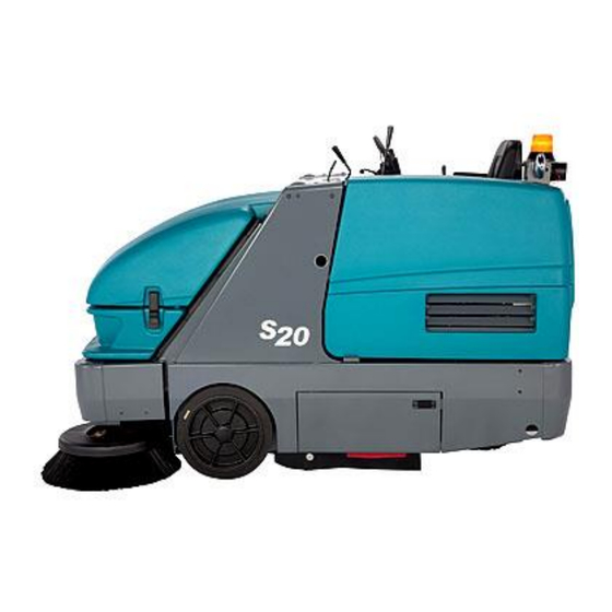
OPERATION OPERATION MACHINE COMPONENTS 1. Operator seat 6. Brush door 2. Steering wheel 7. Fuel tank 3. Instrument panel 8. Hopper access door 4. Hopper cover 9. Main cover 5. Side brush S20 Gas/LP 9006719 (8−2009) -
Page 11: Controls And Instruments
OPERATION CONTROLS AND INSTRUMENTS 1. Directional pedal 17. Hopper door closed light 2. Parking brake pedal 18. Clogged hydraulic filter light 3. Brake pedal 19. Fuel level gauge 4. Seat adjustment lever 20. Hour meter 5. Throttle lever 21. Steering wheel 6. -
Page 12: Symbol Definitions
OPERATION SYMBOL DEFINITIONS These symbols identify controls, displays, and features on the machine. Filter shaker Thermo−Sentry Vacuum fan on Clogged dust filter Vacuum fan off Hopper door closed (light) Fast engine speed Clogged hydraulic filter Idle engine speed LPG fuel level low Hopper down Hourmeter Hopper up... - Page 13 OPERATION Engine water temperature Side brush down and on Side brush up and off Side brush pressure Engine choke (Gasoline Only) Unleaded fuel only Parking brake Brush pressure (Increase) Brush pressure (Decrease) Turn counterclockwise Turn clockwise S20 Gas/LP 9006719 (8−2009)
-
Page 14: Operation Of Controls
OPERATION PARKING BRAKE PEDAL OPERATION OF CONTROLS Press the Brake pedal down as far as possible and use toe to lock the Parking brake pedal into place. Press the Brake pedal to release the DIRECTIONAL PEDAL parking brake. The Parking brake pedal will return Press the top of the Directional pedal to move to the unlocked position. -
Page 15: Main Cover Lever
OPERATION MAIN COVER LEVER MAIN BRUSH ADJUSTMENT KNOB The main cover lever releases and locks the seat The main brush adjustment knob changes the support. amount of contact the main brush has with the surface being swept. Refer to ADJUSTING THE Release: Pull the lever back and lift the main MAIN BRUSH WIDTH section of this manual. -
Page 16: Charging System Light
The engine water temperature light comes on when the temperature of the engine coolant is more than 113_ C (235_ F). If the light comes on, stop operating the machine. Contact a TENNANT service representative. HOPPER TEMPERATURE LIGHT − THERMO−SENTRY The hopper temperature light comes on when the Thermo−Sentry senses that there is excessive... -
Page 17: Lpg Fuel Level Low Light
CLOGGED HYDRAULIC FILTER LIGHT the light comes on, stop operating the machine. The clogged hydraulic filter light comes on when Contact a TENNANT service representative. the hydraulic filter is clogged. If this light remains on, have the hydraulic filter changed as soon as possible. -
Page 18: Fuel Level Gauge
OPERATION FUEL LEVEL GAUGE HOUR METER The fuel level gauge indicates how much fuel is in The Hour meter records the hours the machine the fuel tank. was operated. Use this information to determine machine service intervals. NOTE: Do not use leaded fuels. The use of leaded fuels will cause permanent damage to the system’s oxygen sensor and the catalytic converter. -
Page 19: Operator Seat
OPERATION OPERATOR SEAT The backrest adjustment knob adjusts the angle of the backrest. The front−to−back adjustment lever adjusts the seat position. The front−to−back adjustment lever adjusts the seat position. DELUXE SUSPENSION SEAT (OPTION) The operator seat has three adjustments: backrest angle, operator weight, and front to back. -
Page 20: How The Machine Works
NOTE: The amount and type of soilage play an important role in determining the type of brushes to use. Contact a Tennant representative for specific recommendations. Polypropylene Sand Wedge Main Brush − Recommended for heavy accumulation of sand and other fine particles. -
Page 21: While Operating The Machine
OPERATION WHILE OPERATING THE MACHINE Pick up oversized debris before sweeping. Pick up wire, string, twine, large pieces of wood, or any other debris that could become wrapped around or tangled in the brushes. NOTE: Debris can be placed in the hopper through the hopper access door on the front of the hopper. -
Page 22: Pre−Operation Checklist
OPERATION PRE−OPERATION CHECKLIST - Check the machine for fluid leaks. - Check the main sweep brush for damage and wear . Remove string, banding, plastic wrap, or other debris wrapped around the brush. - Check the main brush compartment right skirt for damage and wear. -
Page 23: Changing The Lpg Tank
OPERATION 5. Unlatch and remove the empty LPG fuel tank CHANGING THE LPG TANK from the machine. 6. Carefully put the filled LPG tank in the 1. Park the machine in a designated safe area. machine so that the tank centering pin enters the aligning hole in the tank collar. -
Page 24: Starting The Machine
OPERATION 3. Move the throttle lever back into the Idle STARTING THE MACHINE engine speed position. 1. LPG powered machines: Open the liquid service valve slowly. NOTE: Opening the service valve too quickly may cause the service check valve to stop the flow of LPG fuel. - Page 25 OPERATION 6. Allow the engine and hydraulic system to warm up three to five minutes. WARNING: Machine emits toxic gases. Severe respiratory damage or asphyxiation can result. Provide adequate ventilation. Consult with your regulatory authorities for exposure limits. Keep engine properly tuned. 7.
-
Page 26: Turning Off The Machine
OPERATION 5. Turn the ignition switch key counterclockwise TURNING OFF THE MACHINE to stop the machine. Remove the switch key. 1. Stop sweeping. 2. Take your foot off the directional pedal. Step on the brake pedal. FOR SAFETY: Before leaving or servicing machine, do not park near combustible materials, dust, gases, or liquids. -
Page 27: Sweeping
OPERATION 4. Move the vacuum and filter shaker lever to SWEEPING the Vacuum fan on position. 1. Ensure that the hopper is completely lowered. 2. Move the throttle lever all the way forward into the Fast engine speed position. NOTE: Only operate the throttle all the way open in the Fast engine speed position when sweeping. -
Page 28: Stop Sweeping
OPERATION 5. Place the main brush lever in the right Main 2. Place the main brush lever in the left Main brush down and on position. The brush will brush up and off position. automatically start rotating. 3. Pull and hold the hopper door lever back until 6. -
Page 29: Emptying The Hopper
OPERATION 5. Drive the machine up to the debris container. EMPTYING THE HOPPER Position the hopper over the debris container. FOR SAFETY: When using machine, move 1. Stop sweeping and shake the filter. machine with care if hopper is raised. 2. - Page 30 OPERATION 8. Pull and hold the hopper door lever back until 11. Push the hopper door lever forward to open the hopper door closed light comes on. the hopper door. 9. Slowly back the machine away from the 12. Move the vacuum and filter shaker lever into debris site or debris container.
-
Page 31: Engaging Hopper Support Bar
OPERATION 4. Pull and hold the hopper raise / lower lever ENGAGING HOPPER SUPPORT BAR back and raise the hopper to the desired height. Release the lever into the Hold position. 1. Set the machine parking brake. FOR SAFETY: When using machine, make FOR SAFETY: When starting machine, keep sure adequate clearance is available before foot on brake and directional pedal in neutral. -
Page 32: Disengaging Hopper Support Bar
OPERATION 6. Slowly lower the hopper so the hopper support bar rests on the support bar stop. DISENGAGING HOPPER SUPPORT BAR 1. Start the machine. WARNING: Lift arm pinch point. Stay clear of hopper lift arms. FOR SAFETY: When starting machine, keep 7. - Page 33 OPERATION 4. Put the support bar in its storage position 7. Shut the machine off. WARNING: Lift arm pinch point. Stay clear of hopper lift arms. 5. Push and hold the hopper raise / lower lever forward to lower the hopper. Release the hopper lever into the Hold position.
-
Page 34: Options
OPERATION 6. Open the access door located at the front of OPTIONS the machine. VACUUM WAND The vacuum wand uses the machine’s vacuum system. The vacuum hose and wand allow pick-up of debris that is out of reach of the machine. -
Page 35: Tower Bumpers (Option)
OPERATION 10. Pull and hold the hopper door lever back until TOWER BUMPERS (OPTION) the hopper door closed light comes on. The tower bumpers help protect the machine from being damaged. Open the tower bumpers before opening the seat support. To open the bumpers: 1. -
Page 36: Machine Troubleshooting
Cyclones dirty / clogged Clear blockage from cyclones Vacuum hose damaged Replace vacuum hose Vacuum fan failure Ensure Thermo Sentry wires are connected Contact TENNANT service per- sonnel Thermo−Sentry tripped Allow Thermo−Sentry to cool Poor sweeping performance Brush bristles worn Replace brushes... -
Page 37: Maintenance
MAINTENANCE MAINTENANCE 7 8 9 MAINTENANCE CHART The table below indicates the Person Responsible for each procedure. O = Operator. T = Trained Personnel. No. of Lubricant Service Person /Fluid Interval Description Procedure Points Resp. Daily Radiator Check fins and cooling fan −... - Page 38 HYDO TennantTrue premium hydraulic fluid or equivalent . . . Special lubricant, Lubriplate EMB grease (TENNANT part no. 01433−1) . . . Water and ethylene glycol anti-freeze, −34_ C (−30_ F) NOTE: More frequent intervals may be required in extremely dusty conditions.
-
Page 39: Lubrication
MAINTENANCE FRONT WHEEL BEARINGS LUBRICATION Repack and adjust the front wheel bearings every 400 hours of operation. FOR SAFETY: Before leaving or servicing machine, stop on level surface, set parking brake, turn off machine, and remove key. ENGINE OIL Check the engine oil level daily. Change the oil and oil filter after every 100 hours of operation. -
Page 40: Hydraulics
MAINTENANCE Drain and refill the hydraulic fluid reservoir with HYDRAULICS new TennantTrue premium hydraulic fluid after every 2400 hours of operation. Machines have a blue colored drop (left photo) on the hydraulic fluid FOR SAFETY: Before leaving or servicing label if originally equipped with TennantTrue machine, stop on level surface, set parking premium hydraulic fluid. -
Page 41: Hydraulic Fluid
(5 gal) Contact appropriate personnel if a leak is discovered. If using a locally−available hydraulic fluid, be sure the specifications match the Tennant hydraulic ATTENTION: Only use TENNANT supplied fluid specifications. Substitute fluids can cause hydraulic hoses or equivalent rated hydraulic premature failure of hydraulic components. -
Page 42: Engine
MAINTENANCE Check the radiator core exterior and hydraulic ENGINE cooler fins for debris daily. Blow or rinse (with low pressure air or water) all dust through the grill and radiator fins, the opposite direction of normal air FOR SAFETY: Before leaving or servicing flow. -
Page 43: Air Filter Indicator
MAINTENANCE AIR FILTER INDICATOR To remove the filter element, raise the hopper and engage the hopper support bar. Set the parking Check the indicator daily. The indicator red line brake and turn the engine off. Remove the top two will move as the air filter element fills with dirt. Do dust skirt clips and pull back the dust skirt to not replace the air filter element until the red line access the air filter housing. -
Page 44: Engine Belt
MAINTENANCE Install the filter element into the air filter housing FUEL FILTER (GASOLINE) and reinstall the dust cap with the water drain The fuel filter traps fuel contaminants. The filter is pointing down. located on the fuel line near the fuel pump. FOR SAFETY: When servicing machine, keep flames and sparks away from fuel system service area. -
Page 45: Carburetor
MAINTENANCE CARBURETOR VACUUM FAN BELT The carburetor has one basic adjustment. Check and adjust the idle speed periodically. Idle speed is 1350 rpm. Check the vacuum fan belt tension and wear after every 200 hours of operation. The correct tension is when the belt deflects 4 mm (0.16 in) from a force of 0.7 kg (1.5 lb) at belt midpoint. -
Page 46: Fuses And Relays
MAINTENANCE Refer to the table below for the fuses and circuits FUSES AND RELAYS protected. Fuse Rating Circuit Protected RELAY PANEL FUSES AND RELAYS 15 A Thermo−Sentry Remove the relay panel cover to access fuses 15 A Engine, Instrumentation and relays. Always replace a fuse with a fuse of 20 A Shaker, Instrumentation the same amperage. -
Page 47: Hopper Dust Filter
MAINTENANCE 3. Remove the dust filter from the hopper. HOPPER DUST FILTER FOR SAFETY: Before leaving or servicing machine, stop on level surface, set parking brake, turn off machine, and remove key. REPLACING THE HOPPER DUST FILTER Shake the dust filter at the end of every shift and before removing the filter from the machine. -
Page 48: Cleaning The Hopper Dust Filter
MAINTENANCE CLEANING THE HOPPER DUST FILTER CLEANING THE CYCLONE ASSEMBLY Use one of the following methods to clean the dust filter: FOR SAFETY: Before leaving or servicing SHAKING−Press the filter shaker switch. machine, stop on level surface, set parking brake, turn off machine, and remove key. TAPPING−Tap the filter gently on a flat surface. -
Page 49: Cyclone Perma−Filter
MAINTENANCE CYCLONE PERMA−FILTER Clean heavy or wet dust and excess debris from the cyclone perma−filter as necessary. Check the cyclone perma−filter for damage every 100 hours of operation. CYCLONE COVER SEALS Check the cyclone cover seals for wear or damage every 100 hours of operation. Clean dust and debris from the cyclones as necessary. -
Page 50: Main Brush
MAINTENANCE 4. Pull the main brush from the main brush MAIN BRUSH compartment. FOR SAFETY: Before leaving or servicing machine, stop on level surface, set parking brake, turn off machine, and remove key. Check the brush daily for wear or damage. Remove any string or wire tangled on the main brush, main brush drive hub, or main brush idler hub. -
Page 51: Checking The Main Brush Pattern
MAINTENANCE CHECKING THE MAIN BRUSH PATTERN ADJUSTING THE MAIN BRUSH TAPER 1. Apply chalk, or a similar marking material, to FOR SAFETY: Before leaving or servicing a smooth and level section of the floor. machine, stop on level surface, set parking brake, turn off machine, and remove key. -
Page 52: Adjusting The Main Brush Width
MAINTENANCE ADJUSTING THE MAIN BRUSH WIDTH SIDE BRUSH(ES) FOR SAFETY: Before leaving or servicing machine, stop on level surface, set parking Check the brush(es) daily for wear or damage. brake, turn off machine, and remove key. Remove any string or wire found tangled in the brush(es) or drive hub(s). -
Page 53: Adjusting The Side Brush Pattern
MAINTENANCE ADJUSTING THE SIDE BRUSH PATTERN SIDE BRUSH PIVOT Check the side brush pattern after every 50 hours The side brush pivot should be checked for of operation. The side brush bristles should touch excessive movement after every 200 hours of the floor in the patterns shown in the illustration. -
Page 54: Skirts, Flaps, And Seals
MAINTENANCE BRUSH DOOR SKIRTS SKIRTS, FLAPS, AND SEALS The brush door skirts are located on the bottom of each of the two main brush doors. The skirt FOR SAFETY: Before leaving or servicing should clear the floor by 3 mm (0.12 in). machine, stop on level surface, set parking Check the skirts for wear or damage and brake, turn off machine, and remove key. -
Page 55: Side Brush Dust Control Skirts (Option)
MAINTENANCE SIDE BRUSH DUST CONTROL SKIRTS HOPPER SEALS (OPTION) The hopper seals are located on the top and side The side brush dust control skirts wrap around the portions of the hopper. side brush and the front bumper. Check the seals for wear or damage after every Check the side brush dust control skirts for wear 100 hours of operation. -
Page 56: Inner Hopper Access Door Seal (Option − Vacuum Wand Only)
MAINTENANCE INNER HOPPER ACCESS DOOR SEAL FILTER CHAMBER INLET SEAL (OPTION − VACUUM WAND ONLY) Check the filter chamber inlet seal for wear or The inner hopper access door seal is located on damage every 100 hours of operation. the hopper and seals the front of the debris hopper. -
Page 57: Brakes And Tires
MAINTENANCE REAR WHEEL BRAKES AND TIRES Torque the rear wheel nuts twice in the pattern shown to 122 to 155 Nm (90 to 110 ft lb) after the first 50 hours of operation, and every 800 hours of BRAKES operation. The mechanical brakes are located on the front wheels. -
Page 58: Pushing, Towing, And Transporting The Machine
MAINTENANCE TRANSPORTING THE MACHINE PUSHING, TOWING, AND TRANSPORTING 1. Position the machine at the loading edge of THE MACHINE the truck or trailer. FOR SAFETY: When loading machine onto PUSHING OR TOWING THE MACHINE truck or trailer, empty hopper before loading If the machine becomes disabled, it can be machine. - Page 59 MAINTENANCE 4. Turn the bypass valve 90_ from the normal The rear tie-down locations are the holes in position before winching the machine onto the the sides of the machine frame near the rear truck or trailer. See PUSHING OR TOWING bumper.
-
Page 60: Machine Jacking
MAINTENANCE MACHINE JACKING STORAGE INFORMATION Empty the hopper before jacking up the machine. The following steps should be taken prior to Jack up the machine at the designated locations. storing the machine for extended periods. Use a hoist or jack capable of supporting the 1. -
Page 61: Specifications
SPECIFICATIONS SPECIFICATIONS GENERAL MACHINE DIMENSIONS/CAPACITIES Item Dimension/capacity Length 2090 mm (82.3 in) Length with side brush 2248 mm (88.5 in) Width 1230 mm (48.5 in) Width with side brush 1260 mm (49.5 in) Height without overhead guard 1260 mm (49.5 in) Height with overhead guard 2085 mm (82.1 in) Track... -
Page 62: General Machine Performance
SPECIFICATIONS GENERAL MACHINE PERFORMANCE Item Measure Maximum forward speed 10 km/h (6 mph) Maximum reverse speed 4.8 km/h (3 mph) Minimum aisle turn width, left 2415 mm (95 in) Minimum turning radius, right 2113 mm (83.2 in) Minimum turning radius, left 1625 mm (64 in) Maximum ramp incline for loading −... -
Page 63: Braking System
SPECIFICATIONS BRAKING SYSTEM Type Operation Service brakes Mechanical drum brakes (2), one per front wheel, rod actuated Parking brake Utilize service brakes, rod actuated TIRES Location Type Size Pressure Front (2) Solid 89 x 410 mm (3.5 X 16 in) −... -
Page 64: Index
INDEX Clogged hydraulic filter light, 15 Control panel Adjust operator seat, 17 Charging Sytem light, 14 Adjusting the Main Brush Taper, 49 Clogged dust filter light, 14 Clogged hydraulic filter light, 15 Adjusting the Main Brush Width, 50 Engine oil pressure, 15 Air filter indicator, 41 Engine water temperature light, 14 Reset, 42... - Page 65 INDEX Emptying the hopper, 27 - 29 Hopper Access door seal, 53 Engaging hopper support bar, 29 - 31 Clogged dust filter, Light, 14 Engine, 40 Disengaging hopper support bar, 30 − 32 Air filter, 41 Door closed, Light, 15 Air filter indicator, 41 Door seals, 54 Belt, 42...
- Page 66 INDEX Adjusting the Taper, 49 Adjusting the Width, 50 Jack points, 58 Replacing or Rotating the Main Brushes, 48 Jacking up the machine, 58 Main Brushes, Adjusting the Taper, 49 Main Brushes, Adjusting the Width, 50 Main Brushes, Replacing or Rotating, 48 Main cover, Lever, 13 Knobs Main brush adjustment, 13...
- Page 67 INDEX Side Brush, Replacing, 50 Side brush(es), Checking brush pattern, 51 Radiator, 40 Check hoses and clamps, 40 Skirts, 52 - 55 Clean core exterior, 40 Brush doors, 52 Hopper Lip, 52 Rear skirts, 52 Hopper side, 52 Rear tie down location, 57 Rear, 52 Side brush dust control, 53 Rear Wheel Support Bearing, 37...
- Page 68 INDEX Vacuum fan, Belt, 43 Vacuum fan belt, 43 Vacuum Wand, 32 Valve clearance, 43 Valves, 43 Intake and exhaust, 43 Wheels, 55 While operating the machine, 19 S20 Gas/LP 9006719 (4−2014)
Need help?
Do you have a question about the GL20 and is the answer not in the manual?
Questions and answers