
Related Manuals for McElroy Talon 2000


Summary of Contents for McElroy Talon 2000
- Page 1 Operator’s Manual Talon™ 2000 Fusion Machine Manual: 7848101 Revision: C 9/20 Original Language: English...
- Page 2 This product and other products could be protected by patents or have patents pending. All the latest patent information is available at patent.mcelroy.com...
- Page 3 Always return the manual to the literature compartment. TX05039-05-04-16 McElroy University For more than 30 years, McElroy has been the only pipe fusion machine manufacturer to continuously offer advanced training. Course offerings are meant to enhance your efficiency, productivity and safety in the proper use of McElroy machines.
- Page 4 No information of knowledge heretofore or hereafter disclosed that disclaimer of warranty shall be construed against McElroy to McElroy in the performance of or in connection with the terms and agrees that such disclaimers herein shall be construed hereof, shall be deemed to be confidential or proprietary, unless liberally in favor of McElroy.
-
Page 5: Table Of Contents
Talon 2000 Radio Remote ........ - Page 6 Talon 2000 Fusion Operation ........
- Page 7 Table of Contents Manual Operation Manual Facing ............4-16 Facing the Pipe .
- Page 8 Talon 2000 Fusion Machine ........
-
Page 10: Safety
Follow all applicable federal, state, local, and industry specific regulations. McElroy Manufacturing, Inc. cannot anticipate every possible circumstance that might involve a potential hazard. The warnings in this manual and on the machine are therefore not all inclusive. You must satisfy yourself that a procedure, tool, work method, or operating technique is safe for you and others. -
Page 11: General Safety
Safety General Safety Safety is important. Report anything unusual that you notice during set up or operation. LISTEN for thumps, bumps, rattles, squeals, air leaks, or unusual sounds. SMELL odors like burning insulation, hot metal, burning rubber, hot oil, or natural gas. -
Page 12: Fuel Handling
Safety Fuel Handling Gasoline and diesel fuels are extremely flammable, and their vapors will explode if ignited. ¡PELIGRO! ¡PELIGRO! Do not fill the fuel tank while the engine is hot or running, as spilled fuel could ignite. Refuel in a well ventilated area. Do not smoke or allow flames or sparks in the area where the engine is refueled, or where fuel is stored. -
Page 13: Pipe Handling Safety
Safety Pipe Handling Safety Do not position yourself or any other personnel under supported or raised pipe. Pipe is heavy and could fall unexpectedly. ¡ADVERTENCIA! Pipe that is bent can store a great amount of energy. Do not bend and force the pipe into the machine. A bent pipe with stored energy can generate tremendous force when that ¡ADVERTENCIA! energy is released. -
Page 14: Electrical Safety
Safety Electrical Safety Frequently inspect electrical cables and unit for damage. Have damaged components replaced and service performed by a qualified electrician. Do not service electrical components while machine is operating. Failure to disconnect the power could result in electric shock. Refer service to ¡ADVERTENCIA! a qualified technician. -
Page 15: Lifting Safety
Safety Lifting Safety Follow all applicable federal, state, local, and industry specific regulations when lifting. ¡ADVERTENCIA! Safety warnings: Do not exceed rated load or lift loads greater than the rated load of the lifting device. Do not operate a damaged or malfunctioning lifting device. Do not lift persons. -
Page 16: Battery
Safety Battery Do not expose the battery to flames or electrical sparks. Hydrogen gas generated by the battery is explosive. Serious injury can result from an exploding battery. ¡ADVERTENCIA! The battery contains acid that can cause burns. Do not allow battery fluid to contact your skin, eyes, fabrics, or painted surfaces. -
Page 17: Facer Cutters Are Sharp
Safety Facer Cutters Are Sharp Facer cutters are sharp and can cut. Never attempt to remove shavings while the facer is running, or is in the facing position between the jaws. ¡ADVERTENCIA! NOTICE: De-energize the machine before attempting any maintenance or adjustment to facer. -
Page 18: Personal Lifting Safety
Safety Personal Lifting Safety The quarter jaws and inserts are heavy. Using one person to lift the jaws and inserts may result in an injury. Two people are required to lift the jaws and inserts. ¡PRECAUCIÓN! ОСТОРОЖНО ATTENTION TX04994-05-03-16 Inside of Pipe is Slippery Inside of pipe is slippery and you could fall resulting in minor to moderate injury. -
Page 19: Safety Label Locations
Safety Safety Label Locations DANGER - Part Number 829201 WARNING - Part Number 8163261 WARNING - Part Number 8163260 WARNING - Part Number 8163275 1 - 10... -
Page 20: Emergency Stop Locations
Safety Emergency Stop Locations Emergency stop buttons are positioned around the machine and when pressed, shuts off the engine and removes hydraulic and electrical power. HMI (Human Machine Interface) Display Emergency stop on top of the housing of the HMI display. -
Page 21: Overview
Overview Theory of Heat Fusion The principle of heat fusion is to heat two pipe surfaces to a designated temperature, and then fuse them together by application of force. This develops pressure which causes flow of the melted materials, which causes mixing and thus fusion. -
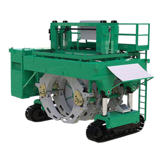
Page 22: Talon 2000
Overview Talon 2000 The Talon 2000 fusion machine consists of an indexer assembly that mounts on to a tracked vehicle. The fusion machine has controls to drive the vehicle from the machine or from a remote control. It picks up/loads pipe from above the pipe and lifts it into the jaws of the carriage. - Page 23 Overview Talon 2000 (continued) ndexer Assembly Catwalk Allows the operator to cross over the pipe to access the other side of the machine. The indexer electrical box is also accessed from the catwalk. Indexer Frame Framing of the indexer that attaches to the vehicle assembly.
- Page 24 Overview Talon 2000 (continued) Fusion Machine HMI Control Panel Machine control panel with a touch screen interface to operate the machine. A remote start button is located on the right side of the control panel. Upper Carriage Jaws Upper jaws of the machine that encircle the pipe. Inserts are available for different pipe sizes.
- Page 25 Overview Talon 2000 (continued) Fusion Machine Indexer Electrical Box 1 1) Contains machine electrical components that control all indexer functions. 12) Power Pack Power pack contains the engine, generator and pumps to power the machine. 13) PLC Electrical Box Contains the electrical components for the power pack. It is also the location of the SIM card.
-
Page 26: Talon 2000 Radio Remote
Overview Talon 2000 Radio Remote Radio Disable Button Pull out on the button to enable the transmission of the radio remote. Move Carriage Switch Open or close the carriage of the machine. Adjust Hydraulic Pressure Increase or decrease the hydraulic pressure to be able to move the carriage. - Page 27 Overview Talon 2000 Radio Remote (continued) 15) Radio Remote Pairing Pairs the transmitter with the receiver of the machine. 16) Radio Remote Power Rotate to switch the remote on or off. Radio Remote Start Up: Power on the radio remote (16) Release the Radio Disable button (1) Wait a few seconds and press the Radio Remote Pairing button to pair the remote to the receiver on the machine.
-
Page 28: Heater
Overview Heater Electric motors and heaters are not explosion proof. Operation of these components in an explosive atmosphere will result in serious injury or death. ¡PELIGRO! ¡PELIGRO! The heater is hot and will burn clothing and skin. Keep the heater in its insulated heat shields when not in use, and use care when heating the pipe. -
Page 29: Hydraulic Fluid Reservior
Overview Hydraulic Fluid Reservoir The filter and filler cap is located on top of the Power Pack with the hydraulic reservoir under the metal cover. The cap has an integral air breather. The tank is equipped with a 10 Micron filter. The reservoir is filled by removing the cap (A) and the filter. -
Page 30: Power And Data Cables
Overview Power and Data Cables The machine has two power cables and two data cables that connect the vehicle to the indexer assembly. The two power cables provide power to the heater and facer assemblies. The data cables provide communications for the indexer and facer assemblies. -
Page 31: Indexer Skid
Overview Indexer Skid The indexer is shipped using the indexer skid. The indexer bolts to the skid at the 4 corners of the skid. It has rest locations for the heater and facer. A toolbox is mounted for the storage of tools required for machine operation and hardware from the fusion machine. -
Page 32: Hmi Navigation Map
Overview HMI Navigation Map Main Screen Settings Machine Settings Control Panel Hardware DataLogger Diagnostics Fusion Alarm Buffer Manual Fusion Current Alarms Machine Con- trols Shipping Process Read- ings Program Information HMI Settings 2 - 12... - Page 33 Overview HMI Navigation Map Configuration Facer Drive Settings Indexer Calibration Heater Drive Task Manager Settings Facer Calibration On Screen Heater Keyboard Temperature Control Heater Calibration Operator Panel Chassis Settings Indexer Drive Settings CPU WEB Server User Administration User Logoff 2 - 13...
-
Page 34: Talon 2000 Interface
Overview Talon 2000 Interface Main Screen Some buttons may not be present unless certain selections or conditions are met. Settings Opens the Control Panel screen Machine Controls Opens the Machine Controls screen which has the controls to drive the machine and operate the carriage and jaws. - Page 35 DataLogger Vault Login Use login credential for an existing DataLogger Vault account. Use the Switch User button to change to a different user. New users, go to vault.mcelroy.com to create an account. TX05006-05-03-16 2 - 15...
-
Page 36: Machine Control Screen
Overview Talon 2000 Interface Machine Control Screen Some buttons may not be present unless certain selections or conditions are met. Close All Jaws Close all of the jaws of the carriage. Open All Jaws Open all of the jaws of the carriage. - Page 37 Overview Talon 2000 Interface Jaw Configuration Change the software setup for jaw configuration. A 2+2 and a 3+1 jaw configuration can be toggled. The machine will still need to be physically changed between the two configurations. 3+1 Jaw Configuration Change the software setup for jaw configuration. This toggles 3+1 jaw configuration for for Stub End Holder fusion of stub ends.
-
Page 38: Manual Facing Screen
Overview Talon 2000 Interface Manual Facing Screen Some buttons may not be present unless certain selections or conditions are met. Indexer Brake Indicates the indexer brake is locked or floating. The red X indicates the brake is floating. Move Indexer Left/Right Move the indexer left and right. - Page 39 Overview Talon 2000 Interface Facer Home Moves the facer frame up and the facer to the home position. Pipe Size The size of the pipe used to calculate the facer operation. The program validates the pipe size to ensure it is a proper pipe size within the range for this machine.
-
Page 40: Manual Fusion Screen
Overview Talon 2000 Interface Manual Fusion Screen Some buttons may not be present unless certain selections or conditions are met. Indexer Brake Indicates the indexer brake is locked or floating. The red X indicates the brake is floating. Move Indexer Left/Right Move the indexer left and right. - Page 41 Overview Talon 2000 Interface Stopwatch Stopwatch to time the different phases of the fusion process. There is a pause/start button and a reset button. Carriage Displacement Displays the displacement of the fusion carriage. This could be used to determine bead-up displacement.
-
Page 42: Control Panel Screen
Overview Talon 2000 Interface Control Panel Screen Some buttons may not be present unless certain selections or conditions are met. Home Opens the Main Screen. Previous Screen Opens the previous screen. Close Application Closes the Talon Control application. This must be done before shutting off the machine. - Page 43 Overview Talon 2000 Interface Program Information Opens the Program Information screen. This contains information about the programs used. Hardware Diagnostic Opens the diagnostic information for the electronic hardware. Shipping Opens the Shipping controls screen. This screen has controls and settings for the shipping/storage operation.
-
Page 44: Machine Settings Screen
Overview Talon 2000 Interface Machine Settings Screen Some buttons may not be present unless certain selections or conditions are met. Home Opens the Main Screen. Previous Screen Opens the previous screen. Jaw Configuration Change between 2+2 jaw configuration and 3+1 jaw configuration. - Page 45 Overview Talon 2000 Interface Indexer Settings Opens the Indexer settings screen. Facer Drive Settings Opens the Facer Drive settings screen. Chassis Settings Opens the Chassis settings screen. Heater Temperature Control Opens the Heater Temperature Control screen. Heater Drive Settings Opens the Heater Drive settings screen.
-
Page 46: Indexer Calibration Screen
Overview Talon 2000 Interface Indexer Calibration Screen Some buttons may not be present unless certain selections or conditions are met. Home Opens the Main Screen. Previous Screen Opens the previous screen. Indexer Controls Controls to move the indexer. The end of travel of the indexer is indicated in that direction by yellow light. - Page 47 Overview Talon 2000 Interface Carriage Target Pressure Adjusts pressure to open and close carriage. Carriage Pressure Indicates the pressure of the carriage. Close/Open Carriage Buttons indicate the direction of the carriage movement. If the carriage does not move, the carriage target pressure can be adjusted.
-
Page 48: Facer Calibration Screen
Overview Talon 2000 Interface Facer Calibration Screen Some buttons may not be present unless certain selections or conditions are met. Home Opens the Main Screen. Previous Screen Opens the previous screen. Indexer Controls Controls to move the indexer. The end of travel of the indexer is indicated in that direction by yellow light. - Page 49 Overview Talon 2000 Interface Carriage Target Pressure Adjusts pressure to open and close carriage. Carriage Pressure Indicates the pressure of the carriage. Close/Open Carriage Buttons indicate the direction of the carriage movement. If the carriage does not move, the carriage target pressure can be adjusted.
-
Page 50: Heater Calibration Screen
Overview Talon 2000 Interface Heater Calibration Screen Some buttons may not be present unless certain selections or conditions are met. Home Opens the Main Screen. Previous Screen Opens the previous screen. Indexer Controls Controls to move the indexer. The end of travel of the indexer is indicated in that direction by yellow light. - Page 51 Overview Talon 2000 Interface Heater On/Off Switch Turn the heater on or off. Heater Temperature Monitor Displays the current temperature of the heater. The red indicator will be lit when the heater is powered on. The green indicator will flash while the heater is coming up to the set point and will stay solid once the temperature has reached the set point.
-
Page 52: Shipping Screen
Overview Talon 2000 Interface Shipping Screen Some buttons may not be present unless certain selections or conditions are met. Home Opens the Main Screen. Machine Shipping Enables and disable the machine shipping controls. Facer Home Moves the facer frame up and the facer to the home position.. - Page 53 Overview Talon 2000 Interface Heater Controls Move the heater up or down to position on the indexer skid. The end of travel of the heater is indicated in that direction by yellow light. Radio Remote Disable Disable and enables the radio remote control to allow the operator to move the vehicle to connect the umbilical cables.
-
Page 54: Hmi Settings Screen
Opens the Main Screen. Previous Page Opens the previous page. McElroy Panel Opens the McElroy Panel screen. This screen allows changes to the operating system (McElroy password protected). Open Screen Keyboard Opens the On Screen Keyboard and the size and position of the keyboard can be adjusted. - Page 55 Overview Talon 2000 Interface CPU Web Server Troubleshooting CPU hardware for Administrators. User Administration Manage users and user passwords. User Logoff Log off the current user from the software. Data/Time Make changes to the date and time used by the software.
-
Page 56: User Administration Screen
Overview Talon 2000 Interface User Administration Screen Some buttons may not be present unless certain selections or conditions are met. Home Opens the Main Screen. Previous Screen Opens the previous screen. User Administration Displays the list of authorized users for the software. The password can be changed by touching an existing user but will require administrator authorization. -
Page 57: Set Up Talon
Set Up Talon Read Before Operating Before operating this machine, please read this manual thoroughly and keep a copy available for future reference. Return manual to the protective storage box when not in use. This manual is to be considered part of your machine. TX00401-9-15-94 Lifting Vehicle Long Legs of... -
Page 58: Starting The Machine
Set Up Talon Starting the Machine Engine Control Box The vehicle will need to be moved close to the indexer assembly so the indexer assembly can be taken out of storage configuration and installed on the vehicle assembly. The vehicle will not operate without the indexer attached. The data jumper connector is required if the indexer is not attached. - Page 59 Set Up Talon Starting the Machine (continued) Å Log in to the application using the operator's passcode. Å The vehicle can now be driven using the HMI or the remote. Å Navigate to the Shipping screen on the HMI and enable the radio remote.
-
Page 60: Remove Heater From Storage Configuration
Set Up Talon Remove Heater from Storage Configuration Use the controls on the Shipping screen on the HMI to raise the heater until the heat shield locks are above the heat shield stop. Heat Shield Stop Heat Shield Lock When the heat shield lock is above the heat shield stop, toggle all 4 locks on the heat shield assembly. - Page 61 Set Up Talon Remove Heater from Storage Configuration (continued) Lower the heater several inches below the heat shield rest. The heater rest pin will no longer be in contact with the heat shield rest. The heater shield will stay in place as it is resting on the heat shield stops. Heat Shield Rest Heater Rest...
-
Page 62: Remove Facer From Storage Configuration
Set Up Talon Remove Facer from Storage Configuration Use the controls on the Shipping screen on the HMI to raise the facer using the jog function on the screen. Raise the facer out of the shipping rest using the jog controls until the end of the facer boom is accessible. -
Page 63: Remove Indexer From Indexer Skid
Set Up Talon Remove Indexer from Indexer Skid The indexer is attached to the skid with 4 bolts. Unbolt all 4 corners of the indexer using the supplied tools included in the toolbox. 3 - 7... -
Page 64: Lifting And Installing The Indexer Assembly
Set Up Talon Lifting and Installing the Indexer Assembly Long Legs of Lifting Sling (Blue) Make sure the vehicle assembly is on level and stable ground with the heater fully raised, facer in the home position and the indexer moved to the full right end of stroke. Connect the lifting sling to the indexer assembly with the two long legs (Blue) of the sling connected to the two lift points away from the catwalk and the other legs (Yellow) connected to the points close to the catwalk. - Page 65 Set Up Talon Lifting and Installing the Indexer Assembly (continued) Lift the indexer assembly and maneuver it over the vehicle assembly. Ensure the 4 quarter twist locks are in the unlocked position. Slowly lower the indexer assembly onto the four quarter twist locks on the vehicle assembly. Quarter twist lock Unlocked Position Once the indexer assembly is resting on the vehicle assembly, turn all 4 quarter...
-
Page 66: Install Upper Jaw Inserts
Set Up Talon Install Upper Jaw Inserts Å Start the fusion machine. Å Log in using the operator passcode. Å On the Main Screen, touch the Machine Controls button on the screen. Å Use the Machine Elevation button on the screen to set the machine height to install upper jaw inserts. - Page 67 Set Up Talon Install Upper Jaw Inserts (continued) Å Start the fusion machine. Å Log in using the operator passcode. Å On the Main Screen, touch the Machine Controls button on the screen. Å Use the Machine Elevation button on the screen to raise the machine up. Å...
-
Page 68: Calibrate Indexer Position
Set Up Talon Calibrate Indexer Position NOTICE: The indexer must be calibrated before the first facing operation of the work day to ensure the interlock's location is set to prevent accidental crashing of the indexer components against the components of the vehicle. To calibrate the indexer position: Å... -
Page 69: Install Sim Card For Datalogger® Vault
Set Up Talon ® Install SIM Card For DataLogger Vault™ Requirements for configuration ® Å PC with Windows and any Web browser Å Standard Ethernet cable Å A SIM card of your mobile network operator or cellular company with data services activated. - Page 70 Set Up Talon ® Install SIM Card For DataLogger Vault™ (continued) Settings on the PC Start the engine. PLC box must be energized to perform this procedure. Å Open the PLC box and locate router (GR1). Å Connect the PC to an available Ethernet port (X2P1 or X2P2) in the router by Å...
- Page 71 Set Up Talon ® Install SIM Card For DataLogger Vault™ (continued) Settings on the PC Click on “Properties”. Å Select “Internet Protocol Version 4” and click on “Properties”. Å Check “Use the following IP Address” radio button. Å Enter IP address and subnet mask shown in the image. Å...
- Page 72 Set Up Talon ® Install SIM Card For DataLogger Vault™ (continued) Establishing connection with the router Configuration is performed with the Web-based administration user interface of the router. Å Start the Web browser on the PC and enter router IP address: https://192.168.1.1/ Å...
- Page 73 Set Up Talon ® Install SIM Card For DataLogger Vault™ (continued) After logging into the system the “System - Overview” screen is shown Å Go to “External Network”, then “UMTS/EDGE”. Å IMPORTANT: Do not change any settings otherwise indicated as follow. Å...
- Page 74 Set Up Talon ® Install SIM Card For DataLogger Vault™ (continued) After saving, power off the router by disconnecting the supply Å voltage connector (See router overview). The compartment for the SIM card is located on the back of the Å...
-
Page 75: Operation
Operation Prepare Heater The heater needs to be cleaned and temperature verified before each fusion joint. Cleaning and recording heater values will be easier to do before loading pipe. Å Touch Manual Operation and then the Manual Fusion button. Å Ensure the heater on. If the heater is not on, turn on the heater. Å... -
Page 76: Load Pipe
Operation Load Pipe The Talon 2000 fusion machine loads pipe into the machine by using the carriage quarter jaws to pull the pipe up into the carriage upper jaws. The fusion machine can clamp onto the middle of the pipe allowing the machine to move pipe into position on the job-site for fusion. -
Page 77: Talon 2000 Fusion Operation
The fusion joint is created to a fusion standard, if an additional standard is needed contact McElroy. Joint reports can be transferred to a usb drive or uploaded to the DataLogger ®... -
Page 78: Datalogger Operation
Operation DataLogger Operation Entering DataLogger operation, the operator will fill out the joint and pipe information. After entering all the information the operator will be able to perform facing operations and then start the data logging of the heating and fusion operations. Joint Information Å... -
Page 79: Machine Information
Operation DataLogger Operation Machine Information The machine information is displayed on this screen. The fusion specification used for the fusion process is selected on this screen. The interfacial pressure according to the selected fusion standard is displayed at the bottom of the screen. Å... -
Page 80: Pipe Information
Operation DataLogger Operation Pipe Information The pipe information is displayed on this screen. The screen will list the fusion type and fusion standard selected from previous screen. The pipe data has inputs for material, pipe size and wall thickness. Å Fusion Type: Displays the fusion type selected from the machine information screen. -
Page 81: Machine Controls
Operation DataLogger Operation Machine Controls The Machine Control screen has the controls for the carriage, jaws and vehicle. The carriage, jaws and vehicle controls can be operated from this screen or from the radio remote. Use these controls to load pipe into the machine. NOTICE: Ensure the jaw braces are in the proper position for the jaw configuration being selected. -
Page 82: Datalogger Facing
NOTICE: The indexer must be calibrated before the first facing operation of the work day to ensure the interlock's location is set to prevent accidental crashing of the indexer components against the components of the vehicle. To calibrate the indexer position, refer to the Set Up Talon 2000 section of this manual. Facing the Pipe: Å... -
Page 83: Drag Pressure
Operation DataLogger Operation Drag Pressure: Drag pressure should be determined using the following procedure: Å Move the carriage so that the faced pipe ends are approximately 3.5" apart. Å Touch the carriage control valve middle (neutral) position. Å Touch the heating mode, and set the middle pressure reducing valve to its lowest pressure. Å... - Page 84 Operation DataLogger Operation Å Lower the facer. Å Shut off the fusion machine. Hydraulically operated equipment is operated under pressure. Anything caught in the machine will be crushed. Keep fingers, feet, arms, legs, and head out of ¡ADVERTENCIA! the machine while operated. Å...
- Page 85 Operation DataLogger Operation Fusion Parameters: On this screen, the fusion standard selected and the calculated fusion values are displayed. When you are ready to start the fusion, touch Start Log..4 - 1 1...
- Page 86 Operation DataLogger Operation DataLogger Fusion: On this screen, the heating and fusion operations are completed. All the controls are available to control the heater and the fusion carriage. Å Lower the heater to end of travel between the pipe ends. Ensure the heater is all the way down. Å...
- Page 87 Operation DataLogger Operation Joint Report: After the fusion joint is complete, the joint report will display. The report will show information about the fusion joint with a table of fusion parameters and the actual recorded values for those parameters. Store the joint report by touching the Fusion Joint Report Storage button. If you receive this message box, you do not have a USB device connected.
- Page 88 Operation DataLogger Operation If you receive this message box, the joint report was successfully stored and sent to the DataLogger Vault. A new fusion joint can be performed. To perform another fusion joint, touch Start a New Fusion Joint. The Joint Report Summary screen will be displayed. 4 - 14...
- Page 89 Operation DataLogger Operation Joint Report Summary: After storing the joint report and touching the Start a New Fusion Joint button, the Joint Report Summary screen will be displayed with fusion parameters used with the last fusion joint. A dialog box will appear asking if you would like to use the stored parameters for the next fusion joint. Touch Yes to use the stored parameters and touch No to enter new parameters for the next fusion joint.
- Page 90 NOTICE: The indexer must be calibrated before the first fusion of the work day to ensure the interlock's location is set to prevent accidental crashing of the indexer components against the components of the vehicle. To calibrate the indexer position, refer to the Set Up Talon 2000 section of this manual. 4 - 16...
- Page 91 Operation Manual Operation Facing the Pipe: Å Enter the pipe size of the pipe being fused. Choose the appropriate unit of measure for the pipe size. There is a pipe size reference button at the bottom of the screen if needed for reference. Å...
- Page 92 Operation Manual Operation Drag Pressure: Drag pressure should be determined using the following procedure: Å Move the carriage so that the faced pipe ends are approximately 3.5" apart. Å Touch the carriage control valve middle (neutral) position. Å Touch the heating mode, and set the middle pressure reducing valve to its lowest pressure. Å...
- Page 93 Operation Manual Operation Å Lower the facer. Å Shut off the fusion machine. Hydraulically operated equipment is operated under pressure. Anything caught in the machine will be crushed. Keep fingers, feet, arms, legs, and head out of ¡ADVERTENCIA! the machine while operated. Å...
-
Page 94: Heating The Pipe
Operation Manual Operation Heating the Pipe: Å Set the temperature according to the temperature range specified in the fusion procedure used. Å Allow the heater to reach the temperature range. Å Lower the heater to end of travel between the pipe ends. Ensure the heater is all the way down. Å... -
Page 95: Special Operations - Jaw Configuration
Special Operation - Jaw Configuration Changing Jaw Configuration The fusion machine can be used with a 2 movable jaw/2 fixed jaw configuration or a 3 movable jaw/1 fixed jaw configuration. To change configuration: Select the desired configuration from the Machine Control screen. Remove the two jaw braces using included tools in the toolbox and install them in the positions that match the selected configuration. -
Page 96: Special Operations - Stub Ends
Special Operation - Stub Ends Configure Machine for Stub End Fusion Install the jaw conversion links (C) between jaws 2 and 3 on both sides that is the appropriate size for the stub end that is being fused. Jaw Conversion Link STUB END LENGTH (INCH) - Page 97 Special Operation - Stub Ends Configure Machine for Stub End Fusion Remove the carriage facer rest buttons from the outer fixed jaw (#1 jaw). Carriage Facer Rest Buttons Install the jaw facer rest button extensions (A) appropriate for the length stub end being fused. Jaw Facer Rest Button Extension Remove the stripper cylinder pushers from the outer fixed jaw (#1 jaw).
- Page 98 Special Operation - Stub Ends Configure Machine for Stub End Fusion On the Machine Control screen, press the Jaw Configuration button to change the configuration from 2 + 2 to 3 + 1. To calibrate the indexer position for 3 + 1: Å...
- Page 99 Special Operation - Stub Ends Configure Machine for Stub End Fusion Attach the lifting fixture assembly to the stub end holder using the two pins and secure it to the holder. Use an overhead lifting device of adequate load rating attached to the lifting fixture assembly and lift the stub end holder.
- Page 100 Special Operation - Stub Ends Configure Machine for Stub End Fusion Using a forklift of proper load rating, lift the stub end holder with the forks on each side of the top spoke of the holder. Drive the holder into position below the upper jaw of jaw #1. Lift the holder up and ensure the stops of the holder rest on the inner surface of jaw #1.
- Page 101 Special Operation - Stub Ends Configure Machine for Stub End Fusion Loosen the slide clamp assemblies and move the clamps to the outer position. Leave approximately 1 inch for the flange, this will allow enough room for the flange to be clamped on. IMPORTANT: Measuring the stub end and using that measurement to locate the distance from the center the slide clamp assembly needs to be positioned.
- Page 102 Special Operation - Stub Ends Configure Machine for Stub End Fusion Attach the 3 over clamp plates loosely. Adjust the alignment bolts and roughly center the stub end. Tighten the over clamp plates. Load pipe into the carriage. Confirm the alignment between the stub end and the pipe. Make adjustments to the alignment if needed and reconfirm the alignment.
-
Page 103: Transport Talon
Transport Talon Transport Talon The Talon must be disassembled and set into a shipping configuration before transportation. Å Set the facer to the home position and raise the heater up to the end of travel. Move the indexer right to the end of travel. Remove Quarter Jaws: The quarter jaws must be removed before shipping. - Page 104 Transport Talon Disconnect the 2 power cables and the 2 data cables. Install the Data Jumper Connector to the vehicle. Remove the extension ladders from the indexer assembly and store on the indexer skid. Remove the pins and loosen the locking nuts on the twist locks. Turn all 4 quarter twist locks to the unlocked position.
-
Page 105: Attach The Indexer Assembly To Indexer Skid
Transport Talon Attach the Indexer Assembly to Indexer Skid Å Position the catwalk over the extension ladders. Lower the indexer assembly on the indexer skid. Ensure the legs of the indexer assembly fit into the four corners of the indexer skid. Å... -
Page 106: Store Facer On Indexer Skid
Transport Talon Store Facer on Indexer Skid Å Lower the machine down using the Machine Elevation button on the Machine Controls screen. Å Ensure vehicle is close enough for the umbilical cables to reach the indexer junction box. If no close enough, drive the vehicle to the skid. Å... -
Page 107: Store Heater On Indexer Skid
Transport Talon Store Heater on Indexer Skid Å Raise the heater up into the heat shield. Leave the heater several inches short of the Heat Shield Rest. Heat Shield Rest Å Remove the heater rest pins from the provided storage location and install the pins into hole below the Heat Shield Rest on both ends of the heater. - Page 108 Transport Talon Store Heater on Indexer Skid (continued) Å Raise the heater slightly until the Heater Shield Lock is off of the Heat Shield Stop. Heat Shield Stop Å Toggle the Heat Shield Lock to retract the lock. Toggle Heat Shield Lock Å...
-
Page 109: Lifting Vehicle
Transport Talon Lifting Vehicle Long Legs of Lifting Sling Follow all applicable federal, state, local, and industry specific regulations including the lifting safety warnings in the General Safety section of this manual when lifting. ¡ADVERTENCIA! Connect the lifting sling to the vehicle with the two long legs (White) of the sling connected to the two lift points on the operator side and the short legs (Yellow) connected near the power pack. -
Page 110: Hardware Diagnostics Screen
Diagnostics Talon 2000 Interface Hardware Diagnostics Screen Some buttons may not be present unless certain selections or conditions are met. Home Opens the Main Screen. Previous Page Opens the previous page. Manifold Rack Displays the I/O modules on the manifold rack. - Page 111 Diagnostics Talon 2000 Interface Indexer Rack Displays the I/O modules on the indexer rack. Diagnostic Scan Scans the I/O modules and if there is a fault, it will display the module in red. Touch the red module to see the error description.
-
Page 112: Current Alarms
Diagnostics Talon 2000 Interface Current Alarms Some buttons may not be present unless certain selections or conditions are met. Home Opens the Main Screen. Previous Page Opens the previous page. Alarm Window Displays information about all of the alarms currently activated. - Page 113 Diagnostics Talon 2000 Interface Acknowledge Alarm The button will show all alarms as viewed and acknowledged. Pressing this button will clear all alarms with status IO and add an A to alarms with a status I. Alarms with a status I are not corrected.
-
Page 114: Chassis Settings Screen
Diagnostics Talon 2000 Interface Chassis Settings Screen Some buttons may not be present unless certain selections or conditions are met. Home Opens the Main Screen. Previous Screen Opens the previous screen. Parking Brake Toggles the Parking Brake on/off. Inclinometer Teach Sets the values of the pitch and roll to zero. - Page 115 Diagnostics Talon 2000 Interface Hydraulic Cylinder Manual Control Buttons to manually control the chassis hydraulic cylinders for the elevation and heater strippers. (Administrator password protected) Track Drive Settings Input fields for adjusting the parameters of the track drive settings. Loop time field is not adjustable.
-
Page 116: Indexer Drive Settings Screen
Diagnostics Talon 2000 Interface Indexer Drive Settings Screen Used primarily for McElroy troubleshooting. Some buttons may not be present unless certain selections or conditions are met. Home Opens the Main Screen. Previous Page Opens the previous page. Indexer Servo-drive Bank of 4 indexer switches for the indexer. (Administrator password protected) Operating status Displays a bank of status blocks. - Page 117 Diagnostics Talon 2000 Interface Positioning control status Displays a bank of status blocks. The green blocks are active. The gray blocks are inactive. Operation Mode Contains Indexer controls and interlocks. Auto Indexer Left - by default (Enabled) raising the heater and facer up will move the indexer to the non fusion zone.
-
Page 118: Facer Drive Settings Screen
Diagnostics Talon 2000 Interface Facer Drive Settings Screen Some buttons may not be present unless certain selections or conditions are met. Home Opens the Main Screen. Previous Screen Opens the previous screen. Operation Mode Contains facer controls , facing direction (CW/CCW) and facer interlocks. (Administrator... - Page 119 Diagnostics Talon 2000 Interface Servo-drive X Ctrl/Status Displays a bank of status blocks. The green blocks are active. The gray blocks are inactive and red blocks are alarms. Touch the red alarms in an attempt to reset it. Servo-drive Y Ctrl/Status Displays a bank of status blocks.
-
Page 120: Heater Drive Settings Screen
Diagnostics Talon 2000 Interface Heater Drive Settings Screen Some buttons may not be present unless certain selections or conditions are met. Home Opens the Main Screen. Previous Screen Opens the previous screen. Control Word 1 Displays a bank of status blocks. The green blocks are active. The gray blocks are inactive and red blocks are alarms. - Page 121 Touching the question mark will display the error at the bottom of the page. Heater Speed Set points Adjust values for the heater speed. (McElroy password protected) Heater Current Values Displays current values for speed, current, torque, temperature and voltage for the heater.
-
Page 122: Heater Temperature Control Settings Screen
Diagnostics Talon 2000 Interface Heater Temperature Control Settings Screen Some buttons may not be present unless certain selections or conditions are met. Home Opens the Main Screen. Previous Screen Opens the previous screen. Heater Temperature Control Settings Adjustable fields for heater control. These fields are administrator password protected. - Page 123 Diagnostics Talon 2000 Interface Heater Temperature Control Calculated Parameters Displays the calculated parameters for the Heater Temperature Control. Error: Difference between the target temperature and current temperature. Heater Element Failure Detector Displays the amperage of two phases of the heater and if the amperage is out of range, the heater will shut down.
-
Page 124: Program Information
Diagnostics Talon 2000 Interface Program Information Some buttons may not be present unless certain selections or conditions are met. Home Opens the Main Screen. Previous Page Opens the previous page. PLC and HMI Program Information Displays the information about the PLC and HMI programs. - Page 125 Diagnostics Talon 2000 Interface Heater Power Red light indicates the heater is powered on. TX05036-05-03-16 8 - 16...
-
Page 126: Process Readings
Displays the pressure that would be seen on the gauge of the hydraulic manifold block on a McElroy fusion machine. Carriage Close Displays the pressure that would be seen on the DataLogger port of the hydraulic manifold block on a McElroy fusion machine. 8 - 17... - Page 127 Diagnostics Talon 2000 Interface Heater CT1 Displays the amperage of one of the two phases of the heater. Heater CT2 Displays the amperage of one of the two phases of the heater. Heater Power Red light indicates the heater is powered on.
-
Page 128: Preventative Maintenance
Maintenance Preventative Maintenance The machine must be kept clean and well maintained. With reasonable care, this machine will give years of service. Therefore, it is important that a regular schedule of preventive maintenance be kept. Service intervals are approximate for average service and may need to be done more frequently in severe service conditions or can be done less frequently if used minimally. -
Page 129: Change Hydraulic Fluid And Filters
Maintenance Change Hydraulic Fluid and Filters The hydraulic fluid and filters should be replaced after every 500 hours or when an alert for hydraulic pressure warning is present on the application. There is a drain valve on the hydraulic reservoir. There is a plug on the end of the valve that must be removed before draining the reservoir. -
Page 130: Adjusting System Pressure
Maintenance Adjusting System Pressure The system pressure for the machine is 3000 psi. A standby pressure of Pressure Compensator 350 psi is used when full system pressure is not required by the machine. Both pressures are adjusted at the pressure compensator in the engine compartment of the power pack of the machine. -
Page 131: Clean Heater Surfaces
Maintenance Clean Heater Surfaces The heater faces must be kept clean and free of any plastic build up or contamination. Before each fusion joint the heater surfaces must be wiped with a clean, non-synthetic cloth. NOTICE: Do not use an abrasive pad or steel wool. Use a non-synthetic cloth that won’t damage surfaces. -
Page 132: Track Tension
Maintenance Track Tension Measure Sag Correct track tension is important to wear of the tracks. If the tracks are too tight or too loose, it will wear rapidly. To check track tension: Place a straight edge across both track idlers. Measure the amount of sag from the straight edge to the track. -
Page 133: Engine Oil
Maintenance Engine Oil Engine Oil Fill Check engine oil according to engine manual maintenance instructions. Change engine oil after the first 50 hours of operation. Following that, change the oil and filter every 500 hours of operation. Refer to the engine manual for engine maintenance instructions. -
Page 134: Pump Drive
Maintenance Pump Drive Check the pump drive oil level with the dipstick (A) while the engine is off. Ensure the oil level is to the MAX oil level on the dipstick. It is recommended to change oil after the first 500 hours or 3 months of service, which ever occurs first. -
Page 135: Remote Batteries
Maintenance Remote Batteries To replace the battery in the remote: Rotate the remote to the bottom. Push the battery away from the tabs holding the battery and lift the battery out of the remote. Use the battery charger to recharge the battery. Replace with a fully charged battery. -
Page 136: Maintenance Checklist
Maintenance Checklist Talon 2000 Fusion Machine INSPECTION CHECKLIST 1. Machine is clean 2. Hydraulic oil is visible in reservoir sight glass 3. Hydraulic hoses are in good condition 4. Hydraulic carriage works smoothly 5. All hydraulic cylinders adjusted (speed and travel) 6. - Page 137 Determining Fusion Pressure Variable Definitions O.D. = Outside Diameter of Pipe (inch) = Wall Thickness of Pipe (inch) π = 3.14 = Standard Dimensional Ratio of Pipe (unitless) = Interfacial Pressure of Pipe (PSI) TEPA = Total Effective Piston Area of Carriage Cylinders (inch²) Formulas O.D.
- Page 138 Hydraulic Fluids Hydraulic Fluids The use of proper hydraulic fluid is mandatory to achieve maximum performance and machine life. Use a clean, high quality, anti-wear hydraulic fluid with a viscosity index (VI) of 135 minimum. It should have a maximum viscosity of 500 cSt (2000 SSU) at startup (ambient temperature) and a minimum viscosity of 13 cSt (65 SSU) at the maximum fluid temperature (generally 80°F above ambient).
-
Page 139: Talon 2000 Fusion Machine
Specifications Talon 2000 Fusion Machine STANDARD DIMENSIONS 193" (4902mm) Maximum Height 148.5" 257.5" (3772mm) (6540.5mm) MINIMUM HOOK HEIGHT SHIPPING DIMENSIONS 13 - 1... -
Page 140: Talon 2000 Fusion Machine
Specifications Talon 2000 Fusion Machine Fusion Machine Weights Complete Fusion Machine: 56,000 lbs (25,401 kg) Vehicle: 46,000 lbs (20,865 kg) Indexer: 10,000 lbs (4,536 kg) Quarter Jaw (2000mm): 145 lbs (66 kg) each Stub End Holder Assembly Weights Talon Stub End Holder: 2,572 lbs (1,167 kg) - Page 141 About this manual . . . McElroy Manufacturing continually strives to give customers the best quality products available. This manual is printed with materials made for durable applications and harsh environments. This manual is waterproof, tear resistant, grease resistant, abrasion resistant and the bonding quality of the printing ensures a readable, durable product.
Need help?
Do you have a question about the Talon 2000 and is the answer not in the manual?
Questions and answers