Table of Contents
Advertisement
Quick Links
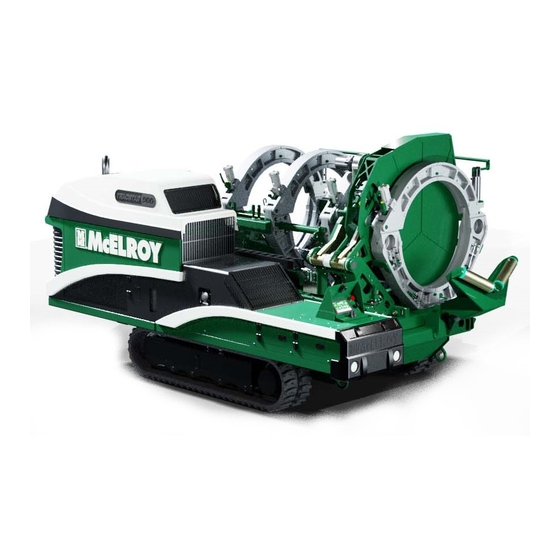
TracStar
Fusion Machines
Models: AT24P0817487, AT24P0888638, AT24P0888654,
AT24P0888656, AT900P0807623, AT900P0888634,
AT900P0888648, AT900P0888650, AT48P0888642
AT48P0808167, AT48P0888644, AT48P0888646
Manual: T48P0898411
Revision: B 08/22
Original Language: English
TracStar® 630i, 900i, 1200i
iSeries
®
Operator's
1
Manual
Advertisement
Table of Contents

Subscribe to Our Youtube Channel
Related Manuals for McElroy TracStar i Series


Summary of Contents for McElroy TracStar i Series
- Page 1 TracStar iSeries ® Fusion Machines Models: AT24P0817487, AT24P0888638, AT24P0888654, AT24P0888656, AT900P0807623, AT900P0888634, AT900P0888648, AT900P0888650, AT48P0888642 AT48P0808167, AT48P0888644, AT48P0888646 Operator’s Manual: T48P0898411 Manual Revision: B 08/22 Original Language: English TracStar® 630i, 900i, 1200i...
- Page 2 Copyright 2021 McElroy Manufacturing, Inc. All rights reserved. P.O. Box 580550 Tulsa, Oklahoma 74158-0550, USA...
- Page 3 If a tool, procedure, work method or operating technique that is not specifically recommended by McElroy is used, you must satisfy yourself that it is safe for you and for others. You should also ensure that the product will not be damaged or be made unsafe by the operation, maintenance or repair procedures that you choose.
-
Page 4: Table Of Contents
McElroy University ........ - Page 5 Carriage Bulkhead ..................3 - 6 Carriage Control Panels .
- Page 6 LIFTING AND TRANSPORT Lifting Safety ................... . . 6 - 1 Lifting Device Shackles .
- Page 7 Replacing Track Gearbox Oil ................9 - 7 Clean Heater Surfaces .
-
Page 8: Literature Information
Read and understand the basic precautions listed in the safety For more than 30 years, McElroy has been the only pipe section before operating or performing maintenance and fusion machine manufacturer to continuously offer advanced repair on this machine. -
Page 9: Patent Information
This product and other products could be protected by patents Refer to the McElroy parts finder at or have patents pending. All the latest patent information is www.mcelroy.com to locate parts for purchase. Reference the available at patent.mcelroy.com model number on the nameplate of the machine when using the parts finder. -
Page 10: Limited Warranty
5 years after shipment, with the exception of purchased items (such as electronic devices, McElroy reserves the right to make any changes in or pumps, switches, etc.), in which case that manufacturer’s improvements on its products without incurring any liability warranty applies. -
Page 11: Safety
If a safety message is attached to a part that is replaced, install a safety message on the replacement part. New safety Wear a hard hat, safety shoes, safety glasses, and other messages can be ordered from McElroy using the part number applicable personal protective equipment. listed. -
Page 12: Do Not Operate In A Hazardous Environment
Do Not Operate in a Hazardous Do not start the engine near spilled fuel. Wipe up spills immediately. Environment Make sure the fuel tank cap is closed tightly and properly secured. Avoid repeated or prolonged fuel contact with skin or breathing of fuel vapor. -
Page 13: Carbon Monoxide
Carbon Monoxide Never push, roll, dump or drop pipe lengths, bundles or coils off the delivery truck, off handling equipment, or into a trench. Always use appropriate equipment to lift, move, and lower the pipe. Engine exhaust gases contain poisonous carbon PERICOLO monoxide. -
Page 14: Battery
Battery Electrical Safety Do not expose the battery to flames or electrical Always ensure equipment is properly grounded. It AVVERTIMENTO AVVERTIMENTO sparks. Hydrogen gas generated by the battery is important to remember that you are working in is explosive. Serious injury can result from an a wet environment with electrical devices. -
Page 15: Unit With Hydraulics
Unit With Hydraulics Positioning and Setting Fusion Machine It is important to remember that a sudden hydraulic oil leak can cause serious injury, or even be fatal if the pressure or oil Place fusion machine on as level ground as possible. temperature is high enough. -
Page 16: Keep Machine Away From Edge Of Ditch
Keep Machine Away From Edge Personal Lifting Safety of Ditch The machine components are heavy. Using one ATTENZIONE person to some machine components may result Heavy equipment too close to a ditch can cause the in an injury. Use two people to lift those machine AVVERTIMENTO walls of the ditch to cave-in. -
Page 17: Sound Information
NOTICE: Failure to follow the pipe manufacturer’s fusion procedures or appropriate joining standard could result in a bad fusion joint. Do Not Modify Machine Make no modifications to your equipment unless specifically recommended or requested by McElroy. TX05340-04-18 TracStar® 630i, 900i, 1200i 2 - 7 Safety... -
Page 18: General Information
GENERAL INFORMATION Theory of Butt Fusion The principle of heat fusion is to heat two pipe surfaces to a designated temperature, and then fuse them together by application of force. This develops pressure which causes flow of the melted materials, which causes mixing and thus fusion. When the thermoplastic material is heated, the molecular structure is transformed into an amorphous condition. -
Page 19: Nomenclature
CD02513-01-07-21 CD02512-01-07-21 Nomenclature H - Lifting Point Covers Covers for the fixed end engine side lifting point. There are Vehicle Console two covers 630i and 900i lifting point A - Vehicle Controls Cover 1200i lifting point Contains the vehicle controls and rotates to reveal the controls The cover will have a lift point label on the cover for the lift and can be stowed and locked below the top cover. -
Page 20: Fuse And Relay Panel
CD02514-01-07-21 Fuse and Relay Panel Carriage Fuse and Relay Block N - Fuse and Relay Legend Label V - Fuse and Relay Block Lists all the fuses and relays contained in this area. Each Contains several different fuses and relays for carriage component is labeled with identifiers, names and any components. -
Page 21: Radio Remote
PH05452-01-11-16 PH05453-01-11-16 PH05451-01-11-16 Radio Remote Remote control of engine and track functions. Engine Speed Engine Side Track Change engine speed Drive the engine side track CRAWL ON between low and high. forward or backward. STANDBY CRAWL OFF Drive Lights Turn drive lights on and off. 10) Remote Pairing Pairs the transmitter to the receiver on the fusion machine. -
Page 22: Outboard Vehicle
CD02515-01-07-21 Outboard Vehicle A - Engine Oil Fill Filler neck for the engine oil. Refer to Engine Operator's manual for checking oil and oil recommendations. B - Engine Oil Dipstick Use to check the oil level of the engine. Refer to Engine Operator's manual for checking oil and oil recommendations. -
Page 23: Carriage Bulkhead
CD02516-01-07-21 Carriage Bulkhead F - Heater Power Receptacle Connects the heater power to the carriage. G - RTD Receptacle Connects the RTD cable to the carriage to measure heater temperature. H - Electrical Control Receptacle Connects the electrical cable to the carriage for electrical control functions. -
Page 24: Carriage Control Panels
CD02517-01-07-21 Carriage Control Panels A - Fixed End Indexer Control Panel Has a 8 button pad for controlling the fixed jaw clamps, fixed jaw pivots, heater and facer pivots. There is a lever for moving the indexer right and left. The panel can be loosened and repositioned in for stowing and out for operation. -
Page 25: Carriage Control Pads
CD02520-01-07-21 Carriage Control Pads Q - Open Movable Jaws Pivots movable jaws to the open position. Fixed End Indexer Control Panel R - Close Movable Jaws Pivots movable jaws to the closed position. E - Unclamp Fixed Jaws Extends clamping cylinders unclamping the jaws. -
Page 26: Carriage Assembly
Jaw Clamps Jaw Clamps Movable Jaws Fixed Jaws CD02526-01-07-21 Carriage Assembly The carriage assembly consists of two fixed jaws and two hydraulically operated movable jaws. The carriage assembly can be removed from the machine in a 3-Jaw or 4-Jaw configuration. Jaw Clamps Jaw clamps are hydraulically operated for clamping and unclamping the upper jaws. -
Page 27: Facer
Facer Stops In-Ditch Facer Handle Storage CD02522-01-07-21 Facer 630i and 900i: For modular facer operations, the in-ditch The facer is a rotating planer-block design. The blade holders each contain three blades and are chain driven (enclosed facer handle can be un-pinned and re-pinned in the in-ditch in lubricant) by a hydraulic motor. -
Page 28: Heater
CD02524-01-07-21 CD02523-01-07-21 Heater Heater Bag Frame The heater is equipped with butt fusion heater plates, coated The heater bag frame protects and insulates the heater when with an antistick coating. the heater is not in use. 630i and 900i - The frame must be manually positioned onto the heater when pivoting the heater in the machine. -
Page 29: Diesel Engine
CD02528-01-07-21 CD02527-01-07-21 Diesel Engine Read and understand the engine owner's manual instructions before operating. The engine owner's manual can be viewed on the Perkins My Engine App which can be downloaded ® and installed from your devices app store. A machine with the Diesel Fuel Only label has an engine capable of using high sulfur diesel fuel. -
Page 30: Hydraulic Fluid Reservoirs
Hydraulic Fluid Reservoirs Hydraulic Fluid Filters The upper fluid reservoir is located under the cowling at the These machines are equipped with three filters and two movable end of the machine. The lower fluid reservoir is magnetic suction filters. One return filter is located on the located under the carriage at the fixed end of the machine. -
Page 31: Vehicle Outriggers (1200I)
Fixed End Outriggers CD02535-01-07-21 Movable End Outriggers CD02536-01-07-21 Vehicle Outriggers (1200i) 1200i: The use of outriggers is recommended to make the machine as level and stable as possible before performing fusion operations. Position the fusion machine on as level ground as possible. -
Page 32: Operator Platform (1200I)
Up Position (Stowed) Platform Link CD02533-01-07-21 Down Position (Operation) CD02534-01-07-21 Operator Platform (1200i) The operator platform is intended to place the operator at a good machine operation height when the machine is stationary. Do not ride on the machine while it is moving. Riding AVVERTIMENTO on the machine could cause the person to fall from or into the machine. - Page 33 TracStar® 630i, 900i, 1200i 3 - 16 General Information...
-
Page 34: Vehicle Display Navigation Map
Vehicle Display Navigation Map Main Screen Service Tracks Voltage Pipe Lifts Lights Security Display Update Display User Settings Information Software GFCI Mode Advanced Heater Settings Facer Mode Outriggers 1200i Only General Information 3 - 17 TracStar® 630i, 900i, 1200i... - Page 35 FAULTS SETTINGS Active Faults Stored Faults Clear All Faults Faults INPUT/OUTPUT SETTINGS Input / Output Perkins ECU Vehicle Inputs Machine Carriage Vehicle Outputs Information Track Calibration SERVICE REMINDERS Service Track Gearbox Air Filter Fuel Filters Reminders Engine Oil & Hydraulic Oil + Alternator &...
-
Page 36: Vehicle Display Screens
Vehicle Display Screens Displays the current hydraulic level. Main Screen Has live information on the engine and hydraulic systems of the machine. The units of measure can be changed on the user settings screen by touching the menu icon in the top left corner Displays the current hydraulic oil of the screen. - Page 37 Opens the user settings screen. Indicates low oil pressure. Indicates low coolant level. Displays the current fuel level of the machine. The gauge Indicates that the hydraulic system is disabled. The hydraulics displays the percentage of the level. The bar will display color can be re-enabled again from the carriage.
- Page 38 Voltage Screen To reset the GFCI, touch the button on the right side of the screen to reset. A prompt displays to confirm the reset. Touch Has live information on the AC parameters of the machine. continue to reset. It displays the phase voltages and currents as well as the To reset the HEFD, touch the button on the right side of the frequency.
- Page 39 Tracks Screen Screen that displays the speed controls for the tracks of the machine. The 2 speeds are Normal and Crawl. Slide your finger across the bar to change the track speed. The track speeds can be calibrated from the Track Calibration screen in the Service Menu.
- Page 40 Pipe Lifts Screen Screen displays the controls for raising and lowering the pipe lifts on each end of the machine. Touch the appropriate indicator arrow to make that adjustment to that pipe lift. Touch the X to close this screen. Service Menu Screen •Track Calibration Touch the X to close this screen.
- Page 41 User Settings Screen Advanced Settings: Touching the Advanced Settings opens a screen with mode Contains user settings for changing: selections for GFCI, Facer and RTD. •Display brightness •Display language •Pressure units of measure •Temperature in °F or °C •Display mode for Day or Night viewing This screen has 2 buttons at the bottom for Display Information and Advanced Settings.
- Page 42 Display Information: On the Security Options screen, the user can select which settings of the machine require a password to change. Shows display information with the component and version. An Update Display Software button is at the bottom of screen. The settings that can be password protected are: •...
- Page 43 Service Reminders Screen •Alternator & Fan Belt •Hydraulic Oil Filters Displays a menu of service reminders and touching the button will open that service reminder screen. Touching the alarm •Engine Oil & Filter button in the top right will enable and disable the alarm. •Engine Coolant Service Reminder Items: Touch the X to close this screen.
- Page 44 Fuel Filters Screen Displays live information about the current run time in (Hours). Displays the time until the next fuel filter service in (Hours) and the time can be reset by pressing the edit button and resetting the service schedule hours. A prompt to confirm the service reminder reset appears.
- Page 45 Engine Belt Screen Displays live information about the current run time in (Hours). Displays the time until the next engine belt service in (Hours) and the time can be reset by pressing the edit button and resetting the service schedule hours. A prompt to confirm the service reminder reset appears.
- Page 46 Engine Oil & Filter Screen Displays the oil and filter service schedule in (Hours). Touching the button resets the service schedule hours. Touch the X to close this screen. Engine Coolant Screen Displays the engine coolant service schedule in (Hours). The time can be reset by pressing the edit button and resetting the service schedule hours.
- Page 47 Input / Output Screen Vehicle Outputs: Displays different input/output sections of the machine and touching any of the buttons will open the screen of that section providing information. Touch the X to close any of these screens. Perkins ECU: PH05747-05-04-21 Carriage: PH05745-05-04-21 Vehicle Inputs:...
- Page 48 Attach the test leads. Touch Start Test to begin test. The test lasts 2 minutes and leaving the screen will cancel the test. This screen will also allow the testing and resetting of the GFCI. PH05846-05-04-21 Do not touch the test leads during the test. PH05748-05-04-21 IMPORTANT: The Fault Current Detection mode displayed during the test is based on the selection made...
- Page 49 Faults Screen Clear Stored Faults: Will display the option to clear Perkins ECU or Vehicle GCM Displays menu for active faults, stored faults and clear all faults. Touching the clear button will clear that type of fault faults. Touching any of the buttons will open the screen of that codes.
- Page 50 Track Calibration Screen Touching Restore Defaults will reset the speeds to the default values. Displays menu of track adjustments. On this screen you can adjust speeds per track for each track speed selection. The speeds can be adjusted for the lever controls and the remote controls.
-
Page 51: Operation - Butt Fusion
OPERATION - BUTT FUSION Read Before Operating Starting from Remote Turn the key switch to RUN to allow the display to power on. Turn the remote power switch (12) to On (I). Ensure remote disable (4) is pulled out. The remote can be paired in Run or Standby (8). Pairing in Run requires the joysticks to be centered. -
Page 52: Driving Vehicle
Driving Vehicle With the Radio Standby switch in "RUN" position and standing at the movable jaw end of the machine, the radio remote left drive joystick drives the carriage side track and the right drive joystick drives the engine side track. Before and while driving machine, ensure all jobsite NOTICE: Be aware that standing at a location other than AVVERTIMENTO... -
Page 53: Prepare Heater
Prepare Heater Heater is not explosion proof. Operation of heater in PERICOLO an explosive atmosphere without necessary safety precautions will result in serious injury or death. ¡PELIGRO! ¡PELIGRO! Make sure both butt fusion heater plates are properly installed. NOTICE: Non-coated heaters should never be used without both butt fusion heater plates installed. -
Page 54: Jaws
Jaws Loading Pipe into Machine Firmly grasp the clamping handle before unclamping. Position pipe support stands slightly more than half the pipe length from each end of the machine to help support and align Press the unclamp button (A) to unclamp the jaws and swing the pipe. -
Page 55: Closing Jaws
Closing Jaws Press the jaw close button (B) to close the jaws. Firmly grasp the clamping handle, move the clamp cylinders into the vertical position and then press the jaw clamp button (A) to clamp the jaws. NOTICE: The jaw clamping cylinders are designed to clamp when in the upright position, evenly applying pressure over the entire base of the cylinder. -
Page 56: Begin Facing
Begin Facing Turn facer on by pressing the facer power button (A). CD02647-05-04-21 PH05827-05-04-21 Turning on the facer opens the facing pressure screen on the tablet. The facing pressure can be adjusted. The facing pressure should be set as low as possible while still facing pipe. -
Page 57: After Facing
After Facing Move the carriage directional control (A) to the right and allow the carriage to open completely. Move indexer (B) to the right to center the facer in between the pipe ends to avoid striking facer stops on the pipe ends. Pivot the facer (C) to the out position. -
Page 58: Check Pipe Alignment
Check Pipe Alignment To correct HI/LO misalignment: From the Fusion Process screen, touch Verify Alignment to open the Check Alignment and Set Pressure screen. Support the clamping cylinders by firmly grasping ATTENZIONE the clamping handle when clamping or unclamping the jaws. Clamping cylinders are heavy and could ¡PRECAUCIÓN! fall causing injury. -
Page 59: Setup Fusion Process
Check Heater Temperature Setup Fusion Process The heater is hot and will burn clothing and skin. ATTENZIONE Keep the heater protected from personnel when not in use and use care when handling heater and ¡PRECAUCIÓN! heating pipe. NOTICE: Incorrect heating temperature can result in ОСТОРОЖНО... - Page 60 Fusion Guide Level: Select the fusion guide level. Level 3 - Automatic fusion Level 2 - Enhanced Guided Workflow Level 1 - Manually controlled fusion Verify Alignment Select to adjust pressure and check alignment. PH05768-05-04-21 Job Summary: Process Type: Select the type of fusion to perform. Joint ID: Enter a joint ID number, this number will increase incrementally for every...
- Page 61 PH05772-05-04-21 PH05857-05-04-21 Weather Conditions: Pressures: Ambient Temperature: Enter the ambient temperature. Bead: Select to change the value. Pipe Temperature: Soak: Enter the temperature of the pipe. Select to change the value. Weather Conditions: Enter the current weather Fuse: Select to change the value. conditions.
- Page 62 PH05857-05-04-21 PH05825-05-04-21 Pressures: Heater Settings: Adjust Drag: Select to change drag value. Reset: Select to reset drag pressure. Change the heater set temperature. Touch Next to proceed to the next screen. Final Review: PH05824-05-04-21 Temperatures: PH05786-05-04-21 Review all the fusion parameters for expected values. Touch Heater Settings: Change the set heater temperature.
- Page 63 Level 3 Fusion Process PH05791-05-04-21 Heat/Soak cycle will start. PH05788-05-04-21 The alarm will sound to alert machine movement. IMPORTANT: Graphs shown on these screens are an example and may not reflect an actual graph of fusion performed to another standard. PH05792-05-04-21 Pressure will drop to drag pressure for Heat/Soak.
- Page 64 PH05794-05-04-21 PH05797-05-04-21 Carriage is opened. Indexer is moved right and the heater is When the Fuse/Cool cycle is complete, a prompt that the removed. Fusion Process Complete appears. Touch OK to accept completion. PH05795-05-04-21 The carriage is closing for fusion. PH05798-05-04-21 Add notes about the completed fusion.
-
Page 65: Level 2 Fusion Process
Level 2 Fusion Process PH05804-05-04-21 Touch Start Soak to begin soak. PH05801-05-04-21 Touch Start Beadup to begin bead-up. Press the Confirm button to confirm start. IMPORTANT: Graphs shown on these screens are an example and may not reflect an actual graph of fusion performed to another standard. - Page 66 PH05807-05-04-21 PH05811-05-04-21 Touch Start Open/Close to begin open/close. Press the Fuse/Cool cycle starts. Touch Stop Cool to stop the cycle. Confirm button to confirm start. PH05860-06-04-21 PH05809-05-04-21 Carriage is opened. Indexer is moved right and the heater is Touch Yes to complete the joint and touch No to continue with removed.
- Page 67 PH05798-05-04-21 Add notes about the completed fusion. PH05799-05-04-21 Take photos of the completed fusion joint. Touch Next to view the Joint Report. TracStar® 630i, 900i, 1200i 4 - 17 Operation - Butt Fusion...
-
Page 68: Level 1 Fusion Process
Level 1 Fusion Process PH05819-05-04-21 Waiting for carriage switch movement to start the Open/ Close. PH05815-05-04-21 Waiting for carriage switch movement to start bead-up. IMPORTANT: Graphs shown on these screens are an example and may not reflect an actual graph of fusion performed to another standard. - Page 69 PH05822-05-04-21 PH05862-06-04-21 Allow Fuse/Cool cycle to run for the specified time. When the Fuse/Cool cycle is complete, a prompt that the Fusion Process Complete appears. Touch OK to accept completion. PH05823-05-04-21 PH05798-05-04-21 Touch Stop Fuse to end the Fuse/Cool cycle at any time. Add notes about the completed fusion.
-
Page 70: Joint Report
Joint Report PH05829-05-04-21 The report, the three plots and any photos taken for the fusion can be viewed at this time. PH05831-05-04-21 After the fusion is completed, the joint report can be viewed. The report, the three plots and any photos taken for the fusion can be viewed at this time. -
Page 71: Special Operations
SPECIAL OPERATIONS Special Operations Overview Outer Fixed Jaw Removal The carriage may be used in a 4-Jaw carriage with just the Certain fusion applications require more clearance than is outer fixed jaw removed or may be used off the vehicle for available in the 4-jaw carriage. - Page 72 Loosen the outer fixed jaw. Remove the 2 bolts securing Connect a lifting strap of appropriate load rating to the the jaw brace and remove. Repeat for the opposite side. upper jaw. Attach the lifting strap to lifting equipment. Re-tighten the outer fixed jaw. Remove the slack from the lifting strap to support the jaw assembly once it is unbolted.
-
Page 73: 4-Jaw Carriage Removal
4-Jaw Carriage Removal Remove the detent pin (A) and extend carriage skid outrigger (B) under the outer fixed jaw. Reinstall the detent pin (A) into the skid with outrigger in open position. Ensure heater and facer are pivoted into the stowage position between the fixed jaws. -
Page 74: Facer Removal
Facer Removal Disconnect the hydraulic hoses to the facer motor (B) 630i and 900i When operating the fusion machine in the 3-Jaw carriage configuration, the facer must be removed from the indexer pivot. Facer blades are sharp and can cut. Never attempt to AVVERTIMENTO remove shavings while the facer is running, or is in the facing position between the jaws. - Page 75 Slowly lift the facer out using an overhead lifting device. Remove the two bolts (G) securing the facer latch (H) and remove. Replace the bolts in the bracket they are removed IMPORTANT: Lifting the heater/facer in and out may from. cause the heater/facer to spin around, use the handle to assist with handling.
- Page 76 630i Facer Setup: Remove the two bolts (G) securing the facer latch (H) and remove. Replace the bolts in the bracket they are removed Remove the rest buttons (K). from. Remove the facer guide rod bracket assembly (L) from the facer assembly by removing the 4 mounting bolts (M).
- Page 77 1200i Facer Setup: Remove the facer guide rod bracket assembly from the heater/facer stand assembly. Attach the facer guide rod bracket assembly (O) to the rear of the facer using the hardware that secured the facer to the indexer pivot arm. CD02603-05-04-21 The facer latch assembly and mounting hardware is stored in the heater/facer stand toolbox.
-
Page 78: Heater Removal
Heater Removal Attach a lifting strap of adequate load rating to the lifting arm attached to the heater (B). 630i and 900i Heater Removal Start the machine, pivot the heater out and leave the heater bag frame out and pivot the heater back in. CD02609-05-04-21 Remove the slack from the lifting strap to support the heater once it is unbolted. - Page 79 1200i Heater Removal The top loading heater must have a stripper bar installed so that the heater can be stripped off pipe ends quickly and When operating the fusion machine in the 3-Jaw carriage efficiently during the fusion process. Stripper bar kits are assembly configuration, the heater must be removed from the available for both the 630i and 900i heaters.
- Page 80 Remove the slack from the lifting strap to support the heater The top loading heater must have a stripper bar installed so once it is unbolted. that the heater can be stripped off pipe ends quickly and efficiently during the fusion process. Remove the heater mounting bolts (C).
-
Page 81: 3-Jaw Carriage Removal
3-Jaw Carriage Removal Disconnect the clamp handle on the inner fixed jaw (D). 630i and 900i Carriage Removal Remove all inserts from the jaws of the carriage. NOTICE: If the 4-jaw carriage has been removed from the vehicle, the carriage skid outrigger must be extended to prevent the skid from tipping over and damaging the carriage. - Page 82 Remove outer guide rod support mounting bolts (G). With the machine turned off and the heater bag frame pivoted out: Disconnect hoses and cable between the 4-jaw carriage and the 3-jaw carriage assembly (C). CD02613-05-04-21 Remove inner fixed jaw mounting bolts (H). CD02612-05-04-21 Disconnect the clamp handle on the inner fixed jaw (D).
-
Page 83: Remove Upper Jaws
Remove Upper Jaws Turn machine power off. Open the Machine Management screen and touch the 630i and 900i Upper Jaws Removal Jaw Removal Mode button. This will relieve pressure in the system to make it easier to disconnect hydraulic quick Attach a lifting strap to an inner upper jaw. - Page 84 Disconnect the pivot cylinder hoses at the quick disconnects (D). Once the hoses are disconnected, exit Jaw Removal Mode on the tablet, start the engine or re-enable the hydraulics. CD02620-05-04-21 Using the lifting strap, lower the upper jaw. Remove the jaw pivot pin (C) Lift the upper jaw from the carriage.
- Page 85 1200i Upper Jaws Removal Close the shut off valves on both outer jaw pivot cylinders (C). The upper jaws of the carriage can be removed so it is easier to maneuver the carriage under pipe in a close quarters in-ditch situation. The upper jaw lifting bracket assembly (A), included in the top loading accessory kit, is required to remove the upper jaws.
- Page 86 Loosen the set screw on the jaw pivot cylinder pin that Use the lifting device to manually pivot the jaw to the closed attaches to the lower jaw (E). position. Drive out the pivot cylinder pin using the brass pin drift punch that's included with the Top Loading Accessory kit (F).
- Page 87 Once the jaw pivot pin is removed, the upper jaw can be lifted away from the carriage. CD02622-05-04-21 Remove the lifting bracket from the inner movable upper jaw, repeat the previous steps to remove other upper jaws. Open the shut-off valves on both outer jaw pivot cylinders. Install carriage with all removed upper jaws around the pipe to be fused.
-
Page 88: Lifting And Transport
Do not shock or impact load the lifting device. Inspect all lifting pins for damage. Lifting Device Shackles The McElroy lifting device utilizes screw pin type anchor shackles for sling attachment points. When installing the shackle screw pin to attachment points, always ensure the screw pin bottoms out completely on its shoulder stop (A) before lifting. -
Page 89: Lifting Entire Machine (630I And 900I)
Lifting Entire Machine (630i and 900i) Hook Position Lifting device configuration shown is for lifting the entire machine including the carriage. NOTICE: Never use this lifting device for any other purpose. You could damage the lifting device and machine. Ensure the heater and facer are in the stowage position between the two fixed jaws. -
Page 90: Lifting Vehicle (630I And 900I)
Lifting Vehicle (630i and 900i) Hook Position Lifting device configuration shown is for lifting the vehicle only without the carriage installed. NOTICE: Never use this lifting device for any other purpose. You could damage the lifting device and machine. Attach the lifting equipment to the lifting device at hook position C. -
Page 91: Lifting 4-Jaw Carriage (630I And 900I)
Lifting 4-Jaw Carriage (630i and 900i) Hook Position Refer to Special Operations section for instructions on disconnecting 4-jaw carriage from vehicle. Lifting device configuration shown is for lifting the 4-jaw carriage. NOTICE: Never use this lifting device for any other purpose. You could damage the lifting device and machine. -
Page 92: Lifting 3-Jaw Carriage (630I And 900I)
Lifting 3-Jaw Carriage (630i and 900i) Hook Position Before disconnecting the 3-Jaw carriage, close the carriage approximately 1 - 2 inches from the fully open position to allow clearance for lifting shackles. Refer to Special Operations section for instructions on disconnecting 3-jaw carriage from vehicle. -
Page 93: Lifting Entire Machine (1200I)
Lifting Entire Machine (1200i) Lifting device configuration shown is for lifting the entire machine including the carriage. NOTICE: Never use this lifting device for any other purpose. You could damage the lifting device and machine. Ensure the heater and facer are in the stowage position between the two fixed jaws. -
Page 94: Lifting Vehicle (1200I)
Lifting Vehicle (1200i) Lifting device configuration shown is for lifting the vehicle only without the carriage installed. NOTICE: Never use this lifting device for any other purpose. You could damage the lifting device and machine. Attach the lifting equipment to the lifting device at hook position C. -
Page 95: Lifting 4-Jaw Carriage (1200I)
Lifting 4-Jaw Carriage (1200i) Refer to Special Operations section for instructions on disconnecting 4-jaw carriage from vehicle. Lifting device configuration shown is for lifting the 4-jaw carriage. NOTICE: Never use this lifting device for any other purpose. You could damage the lifting device and machine. Ensure the heater and facer are in the stowage position between the two fixed jaws. -
Page 96: Lifting 3-Jaw Carriage (1200I)
Lifting 3-Jaw Carriage (1200i) Before disconnecting the 3-Jaw carriage, close the carriage approximately 1 - 2 inches from the fully open position to allow clearance for lifting shackles. Refer to Special Operations section for instructions on disconnecting 3-jaw carriage from vehicle. Lifting device configuration shown is for lifting the 3-jaw carriage. -
Page 97: Securing Indexer For Transport
Securing Indexer for Transport Remove the operator platform from the vehicle: Support the platform and unpin the platform link (A) from the Secure the indexer prior to transport to safeguard against carriage machine damage. Lower the platform (B) down to the horizontal position. To properly secure the indexer into the stowage position: With the heater, heater bag frame, and facer pivoted out, move the heater/facer indexer all the way to the left. - Page 98 Place the platform with tread side down on the vehicle deck. Orient the platform on the vehicle as shown. Pin the platform (E) to the deck using the two platform mounting pins. Use the small holes of the carriage attach points to secure the platform.
-
Page 99: Opening Dome
COWLINGS Opening Dome 1) Remove the grill (C) of the dome. 1) Flip up and turn the latch (A) 90° to unlatch the dome. CD02554-05-04-21 CD02556-05-04-21 2) Open the dome (B) from the movable end of the 2) Through the opening where the grill was, disconnect the machine. -
Page 100: Removing Outboard Side Panel
Removing Grill Panel 4) Loosen the 3 bolts (F) on the pivot locking plates on both sides of the interior of the dome. Slide the plates away from the engine to free the dome pivot rod. 1) Pull up on the handle (H) to unlatch. Unlatch the two side latches (I). -
Page 101: Labels And Markings
LABELS AND MARKINGS Labels and Markings PROP 65 DIESEL EXHAUST WARNING LABEL Part Number - 8163362 PROP 65 BATTERY WARNING LABEL Part Number - 8163361 EMERGENCY STOP LABEL Part Number - 08P0874736 KEYSWITCH LABEL Part Number - 8163361 iSERIES TRACSTAR® VEHICLE CONTROLS LABEL Part Number - 08P0874791 BLUE LIFT POINT LABEL (For 630i and 900i) - Page 102 CD02538-01-07-21 CD02539-01-07-21 630i Part Number - 08P0874786 900i Part Number - 08P0874787 1200i Part Number - 08P0874789 ISRS TRACSTAR MCELROY BRND LBL Part Number - 08P0874783 CD02541-01-07-21 ISERIES GRILL MCELROY BRND LBL Part Number - 08P0874757 SAFETY INSTR MANUAL LABEL...
- Page 103 CD02517-01-07-21 INDEXER CONTROL LABEL Part Number - 08P0874773 PROP 65 BATTERY WARNING LABEL Part Number - 8163361 LARGE MCELROY BRANDING LABEL Part Number - 8163120 EMERGENCY STOP LABEL Part Number - 08P0874736 CARRIAGE CONTROL LABEL Part Number - 08P0874742 TOTAL EFFECTIVE PISTON AREA LBL 630i/900i Medium Force (15.32 in...
- Page 104 BLUE LIFT POINT LABEL (For 630i and 900i) Part Number - MJQ00366 CD02629-01-07-21 SMALL RELAY FUSE BLOCK LABEL Part Number - 08P0844086 CD02630-01-07-21 MEDIUM MCELROY BRANDING LABEL Part Number - 8163119 CD02631-01-07-21 Labels and Markings 8 - 4 TracStar® 630i, 900i, 1200i...
- Page 105 TracStar® 630i, 900i, 1200i 8 - 5 Labels and Markings...
-
Page 106: Maintenance
MAINTENANCE Maintenance Task Schedule Task Clean Machine Inspect Facer Blades Changing Heater Plates/ Adapters Replace Battery and Cables Replace Engine Air Cleaner Element Check/Adjust Track Tension Bleed Air from Carriage Cylinders Adjust Hydraulic Cylinder Cushion Adjust System Pressure Clean Engine Grease Check Hydraulic Fluid Check Machine Operation... - Page 107 Task Inspect Hydraulic Components and Hoses Inspect/Replace Engine Hoses and Clamps Change Hydraulic Fluid and Filter Change Engine Oil and Filter Replace Fuel System Primary Filter (Water Separator) Element Replace Fuel System Secondary Filter Replace Engine Air Cleaner Check/Change Track Gearbox Oil Inspect Aftercooler Core Inspect Alternator...
-
Page 108: Preventative Maintenance
Preventative Maintenance Inspect Facer Blades To insure optimum performance, the machine must be kept Blades bolt directly to the blade holder and should be clean and well maintained. inspected for damage and sharpness. 1) Dull or chipped blades must be replaced. With reasonable care, this machine will give years of service. -
Page 109: Check Hydraulic Fluid
Check Hydraulic Fluid Adjusting Track Tension The hydraulic fluid level should be checked daily. If hydraulic fluid is not visible in the sight gauge, fluid must be The grease in the track tension cylinder is pressurized. added. ATTENZIONE If the grease valve is loosened too far, the valve and Fill in between the 60°C and 80°C temperature mark of the grease can be expelled at high pressure and cause sight gauge when the fluid is cool to allow for fluid volume... -
Page 110: Inspect Heater Plates
Inspect Heater Plates Adjust Hydraulic Cylinder Cushion Inspect the surface of the heater plates when the plates are cool. Inspect the plates for damage or deterioration of the Jaw pivot, heater, and facer hydraulic cylinders are equipped coating on the surface. with cushions which slows the motion of the cylinder near the Replace damaged plates. -
Page 111: Adjusting System Pressure
Adjusting System Pressure Change Hydraulic Fluid and Filters Ensure the machine is off. Do not touch belts and rotating parts while the The hydraulic fluid and filters should be replaced ATTENZIONE approximately every 500 hours of operation or when the engine is running. -
Page 112: Checking Track Gearbox Oil
Replacing Track Gearbox Oil Refer to the "Hydraulic Fluids" section of this manual for hydraulic fluid recommendations. Replace the oil after the first 200 hours of operation. After replacing fluid, circulate fluid 5 minutes to remove all air Subsequent oil changes should be scheduled at least once a before reconnecting carriage. -
Page 113: Clean Heater Surfaces
Clean Heater Surfaces The remote storage (A) and battery charger (B) are behind the vehicle remote storage door (C) The heater is hot and will burn clothing and skin. ATTENZIONE Keep the heater protected from personnel when not in use and use care when handling heater and ¡PRECAUCIÓN! heating pipe. -
Page 114: Battery Replacement And Charging
Battery Replacement and Disconnect the battery by removing the negative (black) cable first and then slide the battery tray (D) out enough to Charging then remove the positive (red) cable. Slide the battery tray out completely. Disconnect battery power by turning the battery disconnect To remove the battery, remove battery holder and lift the switch (A). -
Page 115: Faults
FAULTS Faults 1) Fault Views: Viewing faults out of total amount of faults. 2) SPN (Suspect Parameter Number): Identification number for a particular fault. 3) Fault Location: Device or location where the fault has occurred. 4) FMI (Failure Mode Indicator): Severity level given to a fault. -
Page 116: Hydraulic Fluids
HYDRAULIC FLUIDS Hydraulic Fluids The use of proper hydraulic fluid is mandatory to achieve maximum performance and machine life. Use a clean, high quality, anti- wear hydraulic fluid with a viscosity index (VI) of 135 minimum. It should have a maximum viscosity of 500 cSt (2000 SSU) at startup (ambient temperature) and a minimum viscosity of 13 cSt (65 SSU) at the maximum fluid temperature (generally 80°F above ambient). - Page 117 TracStar® 630i, 900i, 1200i 11 - 2 Hydraulic Fluids...
-
Page 118: Specifications
SPECIFICATIONS TracStar 630i, 900i and 1200i Specifications ® Specifications 12 - 1 TracStar® 630i, 900i, 1200i... - Page 119 Part Numbers AT24P0817487 (630i) AT900P0807623 (900i) AT48P0808167 (1200i) Capabilities 8" IPS - 24" OD 12" IPS - 36" OD 16" OD - 48" OD (225mm - 630mm) (340mm - 900mm) (450mm - 1200mm) Cylinder Force Type - HF, MF HF, MF HF, MF HF, MF Medium Force...
- Page 120 Fusion Pressure 3,000 psi (207 bar) 3,000 psi (207 bar) 3,000 psi (207 bar) Hydraulic System Pressure 3,250 psi (224 bar) 3,250 psi (224 bar) 3,250 psi (224 bar) Hydraulic Reservoir Capacity 23 gallons (87 liters) 23 gallons (87 liters) 23 gallons (87 liters) Facer Power Hydraulic...
-
Page 121: Notes
NOTES Notes TracStar® 630i, 900i, 1200i 13 - 1 Notes...
Need help?
Do you have a question about the TracStar i Series and is the answer not in the manual?
Questions and answers