
Related Manuals for Fintek WINDY 3 HP


Summary of Contents for Fintek WINDY 3 HP
- Page 1 WINDY AIR CONDITIONING 3HP - 4 HP -5 HP - 4 HP I - 5 HP I INSTRUCTION MANUAL 910.100.179GB REV08...
-
Page 2: Table Of Contents
MAIN COMPONENTS WINDY 3 – 3 HP – WINDY 4 – 4HP ....... pag.6 MAIN COMPONENTS WINDY 5 – 5 HP – 5 INVERTER ......pag.7 CAUTION ..................... pag. 8 INSTALLATION .................. pag.8 HOW TO INSTALL IT COMPONENT ............pag.9 ELECTRICAL CONNECTION.............. -
Page 3: Main Components Windy 3 - 3 Hp - Windy 4 - 4Hp
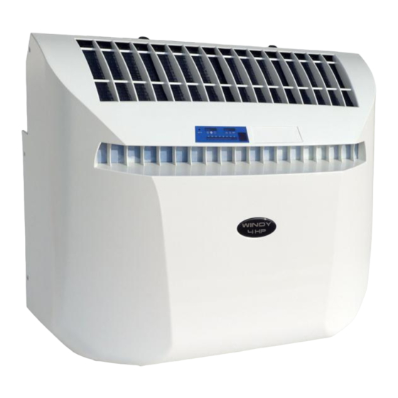
MAIN COMPONENTS WINDY 3 – 3 HP – WINDY 4 – 4HP MAIN COMPONENTS WINDY 3 – 3 HP – WINDY 4 – 4HP Batteries not included MAIN COMPONENTS MAIN COMPONENTS 1 . Air conditioner 8 . External air intake pipe open Ø 150 2 . - Page 4 – – – – Batteries not included MAIN COMPONENTS MAIN COMPONENTS 1 . Air conditioner 8 . External air intake pipe open Ø 150 9 . Internal air delivery pipe Ø 100 2 . Control panel 10. External grid 3 . Electrical cable with plug 11.
-
Page 5: Caution
CAUTION INSTALLATION How to install it This air-conditioner was designed for internal use. To successfully install it and to have optimal - The air-conditioner must be installed vertically on operating performances, follow carefully the instructions contained in this manual. an even surface and on perfectly vertical walls. Non-compliance with installation procedures may (please refer to paragraph ‘Installation’) (Pag. - Page 6 HOW TO INSTALL IT COMPONENT Place the counter-frame on the wall where you wish to install the air- conditioner and, respecting the minimum distances from the walls indicated in picture 1, mark carefully the centre of the air outlet hole. W3-3HP e W4-4HP Ø...
- Page 7 Fix the counter-frame with the tube assembled and inserted in the hole, using expansion tassels. Fig.12 Cut the internal tube with a small saw to a length equal to the length previously measured (Fig 5), plus 50mm WARNING: In case of the mounting from the inside of the air intake grid (“daisy”), the length of the cut must be P+70mm.
-
Page 8: Electrical Connection
ELECTRICAL CONNECTION The air-conditioner is supplied with an electrical cable provided with a Schuko plug. Once the plug is inserted in the socket, the air-conditioner is ready to work. - The connection to the mains must be carried out according to the existing installation rules - Please make sure that the electric plant can supply the necessary current to feed the air-conditioner as well as all the other electric household appliances. -
Page 9: Display Panel
DISPLAY PANEL Remote control description: NOTE: The batteries are not provided with the remote control.Use two 1,5 V manganese or alkaline batteries (stilo) R 03 AAA ▲ Fig.21 STANDARD 1. ON/OFF 2. Increasing temperature push button (+): Increase 1°C 3. Decreasing temperature push button (-): Decrease 1°C 4. -
Page 10: Night Operation
Night operation Activation and disactivation of “AUTO” mode - Press the button (5) of the remote control. The ventilator starts at the maximum speed and the ventilator LED (C) lights up. - To select the ventilator speed press the button (5) of the remote control and select among the three speeds. -
Page 11: Automatic
AUTOMATIC Defrosting Time trajectories around Tset The unit is set to carry out defrosting at regular intervals; when defrosting the leds (B C D) are lighted. The intervals are determined automatically by the unit depending from outside temperature: maximum frequency is every half hour. During defrosting the compressor and the air fan will stop for at least 3 minutes. -
Page 12: Maintenance And Care
for the machine foreseen with the heating pump conditioner, remove the tap from the left bottom side system) of unit (see fi 1). - When the condense water tank is To avoid damage to the compressor, the control empty, please rescrew gently the tap . device stops the air-conditioner and waits for N.B. -
Page 13: How To Clean The Cover
How to clean the cover IMPORTANT To clean the cover of the air-conditioner, dust it with - The batteries have an average life of 12 months in a soft, slightly dampened cloth. normal use. To remove stains, if any, use soap water. - The two batteries must be identical and must be Never use solvents, petrol or any aggressive both replaced at the same time. -
Page 14: Condense Water Tap Kit (Optional)
CONDENSE WATER TAP KIT (OPTIONAL) Part. N° Description Pcs. O-ring Extension Hose connector Hose clamp 80cm Drain hose Tap (remove) Fig. 28 Installation 1) Remove the tap on the bottom of the air-conditioner (part 7). 2) Screw on the previously assembled water tank kit (parts 1 to 4) on the threaded bush you find on the condense water tank. -
Page 15: Technical Data
TECHNICAL DATA TECHNICAL DATA WINDY 3 WINDY WINDY 4 WINDY 3 H.P. 4 H.P. Volume (m³) 60-65 60-65 73-78 73-78 Input power (V) 1 x 220-240 1 x 220-240 1 x 220-240 1 x 220-240 Frequency (Hz) Cooling Power nom. 2.062 2,436 2.062... -
Page 16: Wiring Diagram
WIRING DIAGRAM Legend : Unit control card Control panel Evaporator fan Condensator fan Motor-compressor Disposal of condense water pump Ambient temperature probe Outdoor temperature probe Condense water level sensor 10 . Motor-compressor magnetothermic circuit breaker 11 . Limit temperature probe (only HP type) 12 . -
Page 17: Wiring Diagram Windy Inverter
WIRING DIAGRAM WINDY INVERTER Legenda : 1. Outdoor heat exchange fan 2. Indoor heat exchange fan 3. Condensate drin pump 4 . 4 way valve (only for HP version) 5 . Control panel 6 . Condensate level switch 7 . Compressor 20 di 24... - Page 18 Questo manuale ottempera agli obblighi del DLgs 14 marzo 2014, n. 49 sulla attuazione della direttiva 2012/19/UE sui rifiuti di apparecchiature elettriche ed elettroniche (RAEE) Per RAEE s’intendono i rifiuti di Apparecchiature Elettriche ed Elettroniche (AEE) incluse di tutti i componenti,i sottoinsiemi ed i materiali di consumo che sono parte integrante del prodotto nel momento in cui si assume la decisione di disfarsene.
- Page 19 VIMERCATE 01.03.2016 Ogni intervento o modifica non autorizzati dalla FINTEK faranno decadere la validità di questa dichiarazione. Any tampering or change unauthorized by FINTEK shall immediately invalidate this statement. Eingriffe und Änderungen ohne die Genehmigung von FINTEK machen die vorliegende Erklärung ungültig. Toute opération ou modification non autorisées par FINTEK feront déchoir la validité...
Need help?
Do you have a question about the WINDY 3 HP and is the answer not in the manual?
Questions and answers