Table of Contents
Advertisement
CONTENTS
CW-XC100VK
CW-XC120VK
Page
2
4
5
6
6
7
7
8
10
13
© 2002 Matsushita Industrial Corp. Sdn. Bhd.
(11969-T). All rights reserved. Unauthorized copying
and distribution is a violation of law.
Order No. MAC0208039C1
Room Air Conditioner
Page
18
22
23
25
26
27
28
31
32
Advertisement
Table of Contents

Related Manuals for Panasonic CW-XC100VK


Summary of Contents for Panasonic CW-XC100VK
-
Page 1: Table Of Contents
Order No. MAC0208039C1 Room Air Conditioner CW-XC100VK CW-XC120VK CONTENTS Page Page 1 Functions 11 Installation Instructions 2 Product Specifications 12 Care and Maintenance 3 Dimensions 13 Servicing Information 4 Refrigeration Cycle Diagram 14 Technical Data 5 Block Diagram 15 Electronic Circuit / Main... -
Page 2: Functions
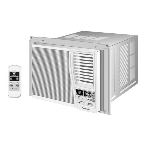
CW-XC100VK / CW-XC120VK 1 Functions 1.1. Remote Control... - Page 3 CW-XC100VK / CW-XC120VK 1.2. Main Unit...
-
Page 4: Product Specifications
CW-XC100VK / CW-XC120VK 2 Product Specifications Unit CW-XC100VK CW-XC120VK Phase Ø Single Single Voltage Frequency Cooling Capacity 2.93 3.37 Btu/h 10,000 11,500 Running Current Input Power 0.98k 1.12k (w/w) Btu/h 10.2 10.2 Starting Current Compressor Output 0.70K 0.75k Fan Motor Output... -
Page 5: Dimensions
CW-XC100VK / CW-XC120VK 3 Dimensions 3.1. Top View, Front View and Side View 3.2. Unit Item Unit: Inch (mm) A - Width 22-1/16” (560) B - Height 14-25/32” (375) C - Depth 23-7/8” (606) 11-9/16” (294) 1-13/16” (46) 11-3/32” (281.6) -
Page 6: Refrigeration Cycle Diagram
CW-XC100VK / CW-XC120VK 4 Refrigeration Cycle Diagram 4.1. CW-XC100VK 4.2. CW-XC120VK Item Pressure (MPa) Temperature (°C) Item Pressure (MPa) Temperature (°C) Lower Upper Lower Upper Lower Upper Lower Upper 1.85 2.05 1.90 2.10 1.82 2.02 1.87 2.07 0.59 0.65 0.57 0.63... -
Page 7: Wiring Diagram
CW-XC100VK / CW-XC120VK 6 Wiring Diagram 6.1. Resistance of Fan Motor 6.2. Resistance of Compressor windings and the rated windings and the rated Capacitor Capacitor Model CW-XC100VK CW-XC120VK Model CW-XC100VK CW-XC120VK Connection CWA951216 CWA951215 Connection CWB09623 CWB09624 34.6 Ω 34.8 Ω... -
Page 8: Troubleshooting Guide
CW-XC100VK / CW-XC120VK 8 Troubleshooting Guide Warning: Disconnect unit from electrical power supply before making any electrical checks. Trouble Check Result Causes Remedy • Supply Voltage • Less than 10% by • Temporary or • Consult ELECTRICIAN, Fan Motor and Compressor won’t run. - Page 9 CW-XC100VK / CW-XC120VK Trouble Check Result Causes Remedy • Temperature Setting. • Higher than room • Reduces capacity. • Set it lower. Insufficient cooling. temperature. • Ventilation door open. • Open. • Restricted air • Close ventilation door. circulation. • Air filter dirty.
-
Page 10: Operation Details
CW-XC100VK / CW-XC120VK 9 Operation Details 9.1. Fan Mode Operation • Fan operation only. Fan in operation according to Remote Control or Main Unit (Touch Control Panel) setting. 9.1.1. Manual Setting of Fan Speed • Basic Fan Speed can be manually adjusted (Lo or Hi) by using the Fan Speed Selection Button/Pad at Remote Control or Main Unit (Touch Control Panel). - Page 11 CW-XC100VK / CW-XC120VK 9.2.6. Cooling Operation Time Diagram 9.3. Jet mode Operation • Purpose of this operation is to obtain the setting temperature quickly. • When the Jet mode is set during Cooling Operation, the set temperature will be automatically decreased 3°C against the present setting temperature (Lowest limit temperature: 16°C).
- Page 12 CW-XC100VK / CW-XC120VK 9.5. Fan Speed Control • Manual Fan Speed Control Basic fan speed adjustment (2 setting, from Lo to Hi) can be carried out by using the Fan Speed Selection Button/Pad at the Remote Control or Main Unit (Touch Control Panel).
-
Page 13: Operating Instructions
CW-XC100VK / CW-XC120VK 10 Operating Instructions 10.1. Parts Identification 10.1.1. Main Unit 10.1.1.1. Vertical Airflow Direction Vane 10.1.1.2. Ventilation Lever Airflow direction adjustment up-down. The ventilation lever must be in CLOSE • The vertical airflow direction vane is position in order to maintain the best cooling controlled by rotating the horizontal conditions. - Page 14 CW-XC100VK / CW-XC120VK 10.1.2. Remote Control Be sure to observe the following: • Aim remote control at the control panel conditioner when operating. • Do not drop or throw the remote control. • Do not place the remote control in a location that is...
- Page 15 CW-XC100VK / CW-XC120VK 10.3. Air Conditioner Operation 10.3.1. Operating the Unit Touch Control Panel Remote Control Display Start operation by pressing OPERATION. • The operation will turn on and the display panel will light up. To stop the operation, press the OPERATION again.
- Page 16 CW-XC100VK / CW-XC120VK 10.3.6. Jet Mode Operation Touch Control Panel Remote Control Display To obtain set temperature quickly: • Press JET MODE. • To cancel this operation, press once more. • After JET MODE is selected, the operation will go on for 15 minutes, after that it will shift back to previous operation mode.
- Page 17 CW-XC100VK / CW-XC120VK 10.3.10. Setting The On Timer Touch Control Panel Remote Control Display Press the TIMER button. • The TIMER indicator light will blink awaiting for setting. Press the TEMP/TIMER “Upward” or “Downward” button until the preferred hour of operation is reached.
-
Page 18: Installation Instructions
CW-XC100VK / CW-XC120VK 11 Installation Instructions 11.1. Installation Box Contents 11.2. Accessories 11.3. Select The Best Location 11.5. Installation procedures 1. Remove the rear cabinet screws and save for later use. 2. Slide the chassis out from the cabinet. 11.4. Window requirements •... - Page 19 CW-XC100VK / CW-XC120VK 3. Secure the cabinet using screws. 11.6. How to Assemble the expandable Panels • Expand the expandable panel fully into the grooves of the window frame, secure the expandable panel, left NOTE: This procedure applies to left and right of a assembling right and top mounting frames to the bottom of the expandable panel.
- Page 20 CW-XC100VK / CW-XC120VK 1. Place the front grille on the cabinet first. 11.12. Place front intake Grille over 2. Secure the front grille to the main chassis using screw. the front grille • Slide the front intake grille slightly to the right to reattach the tabs then push it down to close tight.
- Page 21 CW-XC100VK / CW-XC120VK 3. Remove the front grille. 1. Remove the rubber plug and slide the chassis out from the cabinet a. At bottom right side of the front grille, press inward on cabinet near the power cord, and pull the grille outward to the right until right tabs releases.
-
Page 22: Care And Maintenance
CW-XC100VK / CW-XC120VK 12 Care and Maintenance Caution: Always turn off the air conditioner and the main power supply before unplugging the power cord to clean the unit. Switch off the power supply if the unit is not going to be used for a long period of time. -
Page 23: Servicing Information
CW-XC100VK / CW-XC120VK 13 Servicing Information 13.1. Control Board Removal Procedure 1. Remove the screws in front and both sides of the chassis 4. Pull out the unit from cabinet by holding the hand grip at the as indicated (1), (2) and (3). - Page 24 CW-XC100VK / CW-XC120VK 7. Pull out the control board as shown in figure. Then remove the screw as indicated (1). 8. Release a hook as shown in figure (1) to open up the control board. • Control Board part location.
-
Page 25: Technical Data
CW-XC100VK / CW-XC120VK 14 Technical Data 14.1. Thermostat Characteristics. 14.1.1. CW-XC100VK & CW-XC120VK • Mechanical Thermostat (Cooling) 14.2. Operation Characteristics 14.2.1. CW-XC100VK 14.2.2. CW-XC120VK • Cooling Characteristics Vs. Outdoor Temperature. • Cooling Characteristics Vs. Outdoor Temperature. -
Page 26: Electronic Circuit / Main
CW-XC100VK / CW-XC120VK 15 Electronic Circuit / Main 15.1. Top View 15.2. Bottom View... -
Page 27: Electronic Circuit / Indicator Complete
CW-XC100VK / CW-XC120VK 16 Electronic Circuit / Indicator Complete... -
Page 28: Electronic Circuit Diagram
CW-XC100VK / CW-XC120VK 17 Electronic Circuit Diagram 17.1. Electronic Circuit Diagram (Main Unit) - Page 29 CW-XC100VK / CW-XC120VK...
- Page 30 CW-XC100VK / CW-XC120VK 17.2. Electronic Circuit Diagram (Remote Control) 17.3. How to use electronic circuit diagram Before using the circuit diagram, read the following carefully. • Voltage measurement Voltage has been measured with a digital tester when the fan is set at high fan speed under the following conditions without setting the timer.
-
Page 31: Exploded View
CW-XC100VK / CW-XC120VK 18 Exploded View (Note) • The above exploded view is for the purpose of parts disassembly and replacement. • The non-numbered parts are not kept as standard service parts. -
Page 32: Replacement Part List
CW-XC100VK / CW-XC120VK 19 Replacement Part List Ref. No. Part Name & Description Qty. CW-XC100VK CW-XC120VK Remarks Base Pan Complete CWD52K1048A <----- Bulkhead Complete CWD531010 <----- Air Guide - Propeller Fan CWD311015 <----- Bracket - Fan Motor CWD541046 <----- Ventilation Lever CWH221005 <-----...
Need help?
Do you have a question about the CW-XC100VK and is the answer not in the manual?
Questions and answers