
Subscribe to Our Youtube Channel
Related Manuals for Vecow ESOM-MT-500


Summary of Contents for Vecow ESOM-MT-500
- Page 1 USER USER ESOM-MT-500 Manual Manual Arm-Based MediaTek Genio 500 System on Module 1.0.0 Edition 20220812...
- Page 2 Record of Revision Version Date Page Description Remark 1.00 2022/07/27 Official Release ©Vecow ESOM-MT-500 User Manual...
- Page 3 This manual is released by Vecow Co., Ltd. for reference purpose only. All product offerings and specifications are subject to change without prior notice. It does not represent commitment of Vecow Co., Ltd. Vecow shall not be liable for direct, indirect, special, incidental, or consequential damages arising out of the use of the product or documentation or any infringements upon the rights of third parties, which may result from such use.
- Page 4 Order Information Part Number Description ESOM-MT-500 Arm-Based MediaTek Genio 500 System on Module ESOM-MT-500-EV Arm-Based MediaTek Genio 500 SOM Evaluation Kit ESOM-MT-500-EVP Arm-Based MediaTek Genio 500 SOM Evaluation Kit Plus ©Vecow ESOM-MT-500 User Manual...
-
Page 5: Table Of Contents
1.3.2 Specifications of ESOM-MT-500-CB 1.4 Mechanical Dimension 1.4.1 Dimensions of ESOM-MT-500 1.4.2 Dimensions of ESOM-MT-500-CB CHAPTER 2 GETTING TO KNOW YOUR ESOM-MT-500 7 2.1 Packing List 2.2 ESOM-MT-500 Pinout Table 2.3 Carrier Board I/O Connectors 2.4 Carrier Board Jumpers & Headers... - Page 6 CHAPTER 4 YOCTO SOFTWARE SETUP Introduction 4.1 BSP Installation 4.2 Build Environment Setup 4.3 Image Build APPENDIX A : CONNECTING LCD DISPLAY APPENDIX B : POWER CONSUMPTION ©Vecow ESOM-MT-500 User Manual...
-
Page 7: Chapter 1 General Introduction
Arm Cortex-A73 and quad-core Cortex-A53 processor. It provides a powerful and efficient performance designed for AIoT applications. Vecow ESOM-MT-500 supports LPDDR4 memory up to 4GB and Digital display and MIPI DSI display to facilitate advanced multimedia capabilities. Both Android 10 and Yocto 2.6 operating systems are supported for upgradeability... -
Page 8: Product Specification
1.3 Product Specification 1.3.1 Specifications of ESOM-MT-500 System MediaTek Genio 500 Processor with Quad-core Cortex-A73 Processor @2.0GHz and Quad Cortex-A53 @2.0GHz Memory LPDDR4 SDRAM 4GB eMMC 16GB eMMC • Android 10 • Linux Yocto 2.6 I/O Interface Internal I/O 2 Board to Board Connector Graphics •... - Page 9 70mm x 55mm (2.76" x 2.17") Environment Operating Temperature 0°C to 60°C (32°F to 140°F) Storage Temperature -40°C to 85°C (-40°F to 185°F) Humidity 5% to 95% humidity, non-condensing Relative Humidity 95% at 60°C CE, FCC ©Vecow ESOM-MT-500 User Manual GENERAL INTRODUCTION...
-
Page 10: Specifications Of Esom-Mt-500-Cb
1.3.2 Specifications of ESOM-MT-500-CB System MediaTek Genio 500 Processor with Quad-core Cortex-A73 Processor @2.0GHz and Quad Cortex-A53 @2.0GHz Memory LPDDR4 SDRAM 4GB • Android 10 • Linux Yocto 2.6 Graphics • Digital Display: up to 1920 x 1080 Display • 4-lane MIPI DSI : 1920 x 1080... - Page 11 140mm x 100mm (5.51" x 3.94") Environment Operating Temperature 0°C to 60°C (32°F to 140°F) Storage Temperature -40°C to 85°C (-40°F to 185°F) Humidity 5% to 95% humidity, non-condensing Relative Humidity 95% at 60°C CE, FCC ©Vecow ESOM-MT-500 User Manual GENERAL INTRODUCTION...
-
Page 12: Mechanical Dimension
1.4 Mechanical Dimension 1.4.1 Dimensions of ESOM-MT-500 Unit : mm (inch) 70.00 6.89 56.39 6.72 14.00 51.00 5.00 50.00 1.4.2 Dimensions of ESOM-MT-500-CB Unit : mm (inch) 140.00 ©Vecow ESOM-MT-500 User Manual GENERAL INTRODUCTION... -
Page 13: Chapter 2 Getting To Know Your Esom-Mt-500
GETTING TO KNOW YOUR ESOM-MT-500 2.1 Packing List 2.1.1 ESOM-MT-500 Packing List Item Description ESOM-MT-500: System on Module with MediaTek Genio 500 octa- core Processor, 4GB LPDDR4 SDRAM, 16GB eMMC 2.1.2 ESOM-MT-500-EV Packing List Item Description ESOM-MT-500-EV: MediaTek Genio 500 SOM Evaluation Kit... - Page 14 Item Description Outlook Usage Wi-Fi & BT Antenna 76-4142EXB-006 Antenna Power Power Adapter 71-7442500-3W4 Adaptor Power Cord Power Cord 71-BPWCDUS-004 USB Stick SW Package 81-6PKB000-001 ©Vecow ESOM-MT-500 User Manual GETTING TO KNOW YOUR ESOM-MT-500...
- Page 15 2.1.3 ESOM-MT-500-EVP Packing List Item Description ESOM-MT-500-EVP: MediaTek Genio 500 SOM Evaluation Kit Plus Item Description Outlook Usage Heatsink Heatsink 62-09H0993-1CA COM Cable Cable 61-1300042-100 DC-IN Cable Cable 61-1430212-010 USB to Micro 61-192U2MU- Cable USB Cable Wi-Fi & BT Antenna...
-
Page 16: Esom-Mt-500 Pinout Table
2.2 ESOM-MT-500 Pinout Table 2.2.1 Top Side View 2.2.2 Bottom Side View ©Vecow ESOM-MT-500 User Manual GETTING TO KNOW YOUR ESOM-MT-500... - Page 17 CAM_PDN2 URXD0 CAM_RST2 UTXD0 EINT_RAMDUMP URTS0 UCTS0 CAM_CLK2 GPIO57 GPIO80 GPIO56 GPIO78 GPIO53 GPIO77 GPIO52 GPIO79 GPIO55 GPIO69 GPIO54 GPIO70 AU_VIN2_P MSDC1_DAT1 GPIO 59 MSDC1_DAT0 GPIO177 MSDC1_DAT2 GPIO71 MSDC1_DAT3 WIFI_INT AU_VIN2_N ©Vecow ESOM-MT-500 User Manual GETTING TO KNOW YOUR ESOM-MT-500...
- Page 18 Signal Name Pin No. Signal Name MSDC1_CMD MT7668_PMU_EN GPIO72 MSDC1_CLK AU_VIN0_N AU_VIN0_P USB_P AU_MICBIAS0 USB_N SCL5_MT SDA5_MT AU_LON AU_LOP HOMEKEY_SW SYSRSTB HP_MP3R PWRKEY_SW AU_REFN EINT_EAR HP_MP3L HP_EINT EAR_MIC_P AVSS28_AUD EAR_MIC_N VIO28_PMU ©Vecow ESOM-MT-500 User Manual GETTING TO KNOW YOUR ESOM-MT-500...
- Page 19 IT66121_SYSRSTN DSI0_D3P IT66121_INT DSI0_D0N DPI_D0 DSI0_D0P DPI_D1 DPI_D2 DSI0_D1N DPI_D3 DSI0_D1P DPI_D4 DPI_D5 DSI0_D2P DPI_D6 DSI0_D2N DPI_D7 DPI_D8 DSI0_CKP DPI_D9 DSI0_CKN DPI_D10 DPI_D11 DSI_TE LCM_RST DPI_DE LCD_AVDD_EN DISP_PWM DPI_VSYNC DPI_HSYNC SDA3_MT ©Vecow ESOM-MT-500 User Manual GETTING TO KNOW YOUR ESOM-MT-500...
- Page 20 Pin No. Signal Name Pin No. Signal Name SCL3_MT DPI_CK IDDIG I2S5_BCK GPIO11 DRVBUS I2S5_LRCK KPCOL2 I2S5_DO GPIO151 SDA0_MT SCL0_MT SCL1_MT VSYS SDA1_MT VSYS VSYS GPIO75 VSYS GPIO 60 VSYS VBUS ©Vecow ESOM-MT-500 User Manual GETTING TO KNOW YOUR ESOM-MT-500...
-
Page 21: Carrier Board I/O Connectors
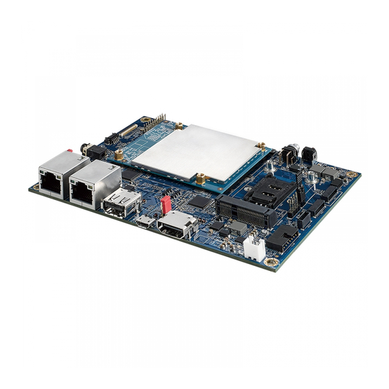
2.3 Carrier Board I/O Connectors 2.3.1 Top View CON402 Digital Display MINIPCIE1 LAN1 LAN2 PWRBTN JDSI CON2 CON3 CON1 JTOUCH ©Vecow ESOM-MT-500 User Manual GETTING TO KNOW YOUR ESOM-MT-500... - Page 22 2.3.2 JBAT1: Battery The ESOM-MT-500-CB is equipped with a real-time clock, powered by a lithium battery. To charge the rechargeable lithium battery, there is a battery charger connector, labeled as ‘BAT1’. It is recommended that you not replace the lithium battery on your own, but if the battery needs to be changed, please contact the Vecow RMA service team.
- Page 23 OUTP_R 2.3.5 USB: USB 2.0 Port The USB interface supports 480Mbps transfer rate complied with high speed USB specification Rev. 2.0. Pin No. Signal Name USB Data - USB Data + ©Vecow ESOM-MT-500 User Manual GETTING TO KNOW YOUR ESOM-MT-500...
- Page 24 The Digital Display port uses an HDMI Type A receptacle connector to connect High Definition video and digital audio using a single cable. Digital Display Pin No. Signal Name Pin No. Signal Name CLK- DDC_CLK DDC_DATA HDMI_5V PLUG_DET CLK+ ©Vecow ESOM-MT-500 User Manual GETTING TO KNOW YOUR ESOM-MT-500...
- Page 25 RJ-45, which is fully compliant with the IEEE 802.3 (10BASE-T) and 802.3u (100BASE-TX) standards. Using suitable RJ-45 cable, you can connect the ESOM-MT-500-CB to a computer or to any other devices with Ethernet connection, for example, a hub or a switch. The pinouts of the 10/100Mbps Ethernet ports are listed below.
- Page 26 The Micro USB 2.0 port is used for downloading the OS image. The pinouts of the Micro USB 2.0 port are shown below. CON402 Pin No. Signal Name VBUS USB_DATA- USB_DATA+ ©Vecow ESOM-MT-500 User Manual GETTING TO KNOW YOUR ESOM-MT-500...
- Page 27 2.3.9 SW7: Reset Button ESOM-MT-500-CB comes with a reset button. If the system have error or frozen, you can press the Reset button to restart. 2.3.10 PWRBTN: Power Button To boot on the system, please quickly press the button once. To shut down the system, please press the button for more than 4 seconds.
- Page 28 Signal Name Pin No. Signal Name Reserved VDD3V3_MPCIE Reserved Reserved VDD1V5 Reserved USIM VCC USIM DATA Reserved USIM CLK Reserved USIM RESET USIM VPP Reserved Reserved MPCIE_W_DISABLE MPCIE_RST_N Reserved VDD3V3_MPCIE Reserved ©Vecow ESOM-MT-500 User Manual GETTING TO KNOW YOUR ESOM-MT-500...
- Page 29 The external Nano SIM card offers wireless communication capability to the system. The pinouts of the SIM card slot are listed below. SIM1 Pin No. Signal Name USIM_VCC_A USIM_RST_A USIM_CLK_A USIM_VPPSIM_A USIM_DATA_A ©Vecow ESOM-MT-500 User Manual GETTING TO KNOW YOUR ESOM-MT-500...
- Page 30 There are two Serial ports (COM, COM1). COM is used for debugging and COM1 can be configured for RS-232 mode. The pin assignments are listed in the following table: COM1 Pin No. Signal Name Pin No. Signal Name COM_RXD0 COM_RXD1 COM_TXD0 COM_TXD1 ©Vecow ESOM-MT-500 User Manual GETTING TO KNOW YOUR ESOM-MT-500...
- Page 31 2.3.14 J3: DC Power input ESOM-MT-500 supports 12V DC power input by wire-to-board connector. The pinouts are listed below. Pin No. Signal Name 12VIN ©Vecow ESOM-MT-500 User Manual GETTING TO KNOW YOUR ESOM-MT-500...
- Page 32 The pin assignments are listed in the following table: Pin No. Signal Name Pin No. Signal Name RDP0 CLKN RDN0 CLK of sensor RDP1_B RDN1_B Reset I2C_DATA I2C_CLK 1.8V 1.5V 2.8V 2.8V CLKP ©Vecow ESOM-MT-500 User Manual GETTING TO KNOW YOUR ESOM-MT-500...
- Page 33 Signal Name Pin No. Signal Name 3.3V 3.3V DSI_D0P DSI_D0N LCD VDDEN Backlight_PWM DSI_D3P I2C_DATA DSI_D3N I2C_CLK DSI_D2P DSI_D2N AGING DSI_D1P DSI_D1N Backlight power Backlight power DSI_CKP Backlight power DSI_CKN Backlight power ©Vecow ESOM-MT-500 User Manual GETTING TO KNOW YOUR ESOM-MT-500...
- Page 34 There is a touch screen connector, which is used for connecting the touch screen controller. The pin assignments are listed in the following table: JTOUCH Pin No. Signal Name Interrupt I2C_CLK I2C_DATA 3.3V Reserved ©Vecow ESOM-MT-500 User Manual GETTING TO KNOW YOUR ESOM-MT-500...
- Page 35 Reserved 2.3.19 CON1-3: IPEX Connectors There are three IPEX connectors labeled ’CON1’, ‘CON2’ and ‘CON3’. ‘CON2’ is for Bluetooth antenna and ‘CON1’ and ‘CON3’ are for Wi-Fi antennas. CON1 CON2 CON3 ©Vecow ESOM-MT-500 User Manual GETTING TO KNOW YOUR ESOM-MT-500...
-
Page 36: Carrier Board Jumpers & Headers
To "open" a jumper, you remove the clip. Sometimes a jumper will have three pins, labeled 1, 2, and 3. In this case you would connect either pins 1 and 2, or 2 and 3. ©Vecow ESOM-MT-500 User Manual GETTING TO KNOW YOUR ESOM-MT-500... - Page 37 There is a watchdog jumper labeled as ‘J15’, which is used to enable or disable the watchdog function on the board. The watchdog jumper settings are as below. Pin No. Definition Disabled ©Vecow ESOM-MT-500 User Manual GETTING TO KNOW YOUR ESOM-MT-500...
- Page 38 I²C, SPI, and 12 GPIO devices. The pin assignments are listed as below. Pin No. Signal Name Pin No. Signal Name SPI_CLK SPI_CS SPI_MISO SPI_MOSI GPIO79 GPIO53 GPIO80 GPIO54 GPIO52 GPIO78 GPIO77 GPIO57 I2C_CLK1 GPIO56 I2C_DATA1 GPIO55 GPIO69 1.8V GPIO70 ©Vecow ESOM-MT-500 User Manual GETTING TO KNOW YOUR ESOM-MT-500...
-
Page 39: Chapter 3 Android Software Setup
This Development Guide describes the way to set up the essential development environment, so that users can customize the Android source code and come up with their own image for the ESOM-MT-500. 3.1 BSP Installation The following are contents in the BSP package. -
Page 40: Build Environment Setup
$ sudo apt-get install git-core gnupg flex bison gperf build-essential zip curl zlib1g-dev gcc-multilib g++- multilib libc6-dev-i386 lib32ncurses5-dev x11proto-core-dev libx11-dev lib32z-dev libgl1-mesa-dev libxml2-utils xsltproc unzip make python-networkx mingw32 zlib1g-dev:i386 tofrodos libswitch-perl ©Vecow ESOM-MT-500 User Manual ANDROID SOFTWARE SETUP... -
Page 41: Image Build
3.3 Image Build This section explains how to use the source code to build the image for the firmware installer on the ESOM-MT-500. 3.3.1 Building the Android Image Type below commands for the image building. $ cd android10 $ source build/envsetup.sh; lunch full_tb8788p1_64_wifi- userdebug $ make 2>&1 | tee build.log... -
Page 42: Chapter 4 Yocto Software Setup
This Development Guide describes the way to set up the essential development environment, so that users can customize the Yocto source code and come up with their own image for the ESOM-MT-500. 4.1 BSP Installation The following are contents in the BSP package. -
Page 43: Build Environment Setup
The following gn tools are required and can be installed using the commands below: $ wget -O gn http://storage.googleapis.com/chromium- gn/3fd43e5e0dcc674f0a0c004ec290d04bb2e1 c60e $ sudo chmod 777 gn $ sudo mv gn /usr/bin/ ©Vecow ESOM-MT-500 User Manual YOCTO SOFTWARE SETUP... -
Page 44: Image Build
4.3 Image Build This section explains how to use the source code to build the image for the firmware installer on the ESOM-MT-500. 4.3.1 Building the Yocto Image Type the commands below to build the image. $ cd yocto2.6 $ export TEMPLATECONF=${PWD}/meta/meta-mediatek- mt8385/conf/base/aiv8385-linux.aiot-emmc... -
Page 45: Appendix A : Connecting Lcd Display
APPENDIX A : CONNECTING LCD DISPLAY A.1 Function Description JDSI JTOUCH ©Vecow ESOM-MT-500 User Manual Appendix A... - Page 46 Step 1 Attached the 34-pin FFC cable to the MIPI DSI connector, labeled as ‘JDSI’ on the ESOM-MT-500-CB, AND then attach the other end of the cable to the 10.1’’ TFT-LCD display. ©Vecow ESOM-MT-500 User Manual Appendix A...
- Page 47 Step 2 Attached the 8-pin FFC cable to the Touch connector, labeled as ‘JTOUCH’ on the ESOM-MT-500-CB, AND then attach the other end of the cable to the 10.1’’ TFT-LCD display. ©Vecow ESOM-MT-500 User Manual Appendix A...
-
Page 48: Appendix B : Power Consumption
AnTuTu Stress Test B.1 MediaTek Genio 500 Processor Power on and boot to Android 10 Android 10 Power idle status CPU Stress Test Input Max Current Max Consumption Max Current Max Consumption 0.3809A 4.5708W 0.7948A 9.5376W ©Vecow ESOM-MT-500 User Manual Appendix B... - Page 49 No part of this publication may be reproduced in any form or by any means, electric, photocopying, or recording, without prior authorization from the publisher. The rights of all the brand names, product names, and trademarks belong to their respective owners. © Vecow Co., Ltd. 2022. All rights reserved.
Need help?
Do you have a question about the ESOM-MT-500 and is the answer not in the manual?
Questions and answers