
Related Manuals for Huazheng HZNZ-100


Summary of Contents for Huazheng HZNZ-100
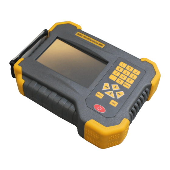
- Page 1 HZNZ-100 Battery Impedance Tester Huazheng Electric Manufacturing (Baoding) Co.,Ltd...
- Page 2 (0312) 6775656 to tell you to serve you at all times- Baoding Huazheng Elect ric Manufact ur ing Co. , Lt d. , our company will def initely make you satisf ied !
-
Page 3: Table Of Contents
Contents I.Summarize............................. 1 II.Junction Port And Cables Instruction..................3 III.Operation Rules.......................... 5 IV.PC Software Instruction......................20 Chapter V Maintenance And Warning..................23 VI.Packing List..........................25... -
Page 4: I.summarize
I.Summarize 1.1 General This accumulator internal resistance tester utilized colour resistance touch screen. It can be operated via finger or the touch pen with convenience and flexibility. It is portable and the data can be known soon exactly. This instrument can store and process data of battery voltage and internal resistance. - Page 5 Via SD card port all test data can be stored in PC permanently. Track and analyze the battery “medical record”. Powerful data management. The instrument can be used separately without computer. Strong overload protection on power. Make it work more reliable. ...
-
Page 6: Ii.junction Port And Cables Instruction
II.Junction Port And Cables Instruction 2.1 Instrument port Fig 2.1 Instrument port Test line port: Open the cap and insert wire here SD card port: Insert the SD card here Charging port: Charge the instrument here Keys: ... - Page 7 2.2.2 battery connection diagram Fig 2.2.2 Poles connection Fig 2.2.2-1 Connect connection strip Fig 2.2.2 -2 Connection strip test 2.2.3 Test battery pole When we test one group battery please test one battery all poles and connection strip (if there is) completely then begin next battery test. We can select any way to test different poles of one battery but please make sure all battery direction are same.
-
Page 8: Iii.operation Rules
Before it is going to testing a battery bank, it has to finish all testing of poles and connectors of one battery, then start to testing next battery. First, test the poles, and then test the connectors. When finished testing of all poles and connectors of one battery, test the next cell battery poles and connectors as the same direction. - Page 9 test. 2) If automatic test every time change on test clip the instrument will test automatically don’t need manual click. Pole quantity setting. According to poles quantity to set. Test mode: 1) Test the connection strip resistance. 2) Select “test connection strip” If don’t test select “test on pole”. Test item: ...
- Page 10 whole battery group test was not finished when return but want to go on test click “Test battery” the test will be continued as per last test. Sixth step: data check : “Data Mgmt” Select certain files and click “View” We’ll find detail data.
- Page 11 Fig.3.2.1Specifications setting New battery specification: Custom setting on battery test specification. Existing battery specification: Specifications of former test battery. Fig.3.2.1-1New battery specification setting Machine room number: 0001-9999. Technician number: 0001-9999. Battery group number: 0001-9999. Battery quantity: 1-500(The continuous test can be made for 500 pcs battery at ...
- Page 12 automatically don’t need manual click. Pole quantity: 2/4/6/8 Test mode: 1) Test on pole: Just test pole internal resistance. 2) Test the connection strip: Test pole internal resistance then test the resistance of pole connection strip. Test item ...
- Page 13 3.3 Start Test Parameters setup interface click “ ”, ready enter into test interface. Fig.3.3 Start test Connecting test line. Select “Yes” enter the test interface. 3.3.1 test interface Test item is different from test mode , different interface, see below figure . ...
- Page 14 Fig 3.3.3-2 More than 2 poles voltage and internal resistance test Fig 3.3.3-3 More than 2 poles and connection strip test on voltage and internal resistance Fig. 3.3.3-4 All battery group after tested Test status: In the test or soon to finish. ...
- Page 15 Connection resistance: Test resistance between pole connection strip. Re-test: Test battery again and replace last data when save new data. If manual test then each change on test clip will request us to click “Start test” for next test.
- Page 16 3.5 Data management 3.5.1 Data save: internal storage and external storage (SD Card ). Main interface “ ” , enter into data management interface. 3.5.2 External storage Fig.3.5.2 External storage interface Name the file: R machine room number-battery group number-test date. ...
- Page 17 Fig.3.5.3Internal storage interface Internal storage data will be transferred to computer via SD card for analysis. Delete all: Click it to delete all record. Delete: Select certain record and then click it will delete present record. Click :Download all” the data will be transferred to SD card. ...
- Page 18 “------”means this item has not been tested. Keys: Setting check: Set the check specifications. Column chart: All data of test battery displayed via column chart. Including voltage, internal resistance, volume. Data test:View detailed test data. Last page/Next page to check other battery data.
- Page 19 Last line/Next line to check other battery information. Fig. 3.5.4-3 Continue test Battery group test was not finished. Start any battery test connect test strip. Clik “Yes” start the test. 3.6 Re-test Retest the battery Main interface” ” —...
- Page 20 Fig. 3.7 System setting/data setting interface 3.8 Touch screen calibration Main interface “ ” — “ ” enter into calibration interface . Fig. 3.8 Touch screen calibration Click “Yes” Touch screen calibration utilized 5 points mode click the “+” orderly. When finish calibration it will return automatically.
- Page 21 Fig. 3.9 System setting Automatic off time: Maximum value is 120 minutes, 0 means no automatic off. Back light off time: Maximum value is 120 minutes, 0 means no automatic off. Alarm volume: Close-voltage lower than minimum level won’t alarm; Open-alarm ...
- Page 22 Fig. 3.11-1 Add new manufacturer Battery manufacturer name contains 4 letter or number at most. Fig. 3.11-2 Add manufacturer data Voltage type: Select it according to battery type. Battery volume: Input battery volume. Reference internal resistance: Input the internal resistance from manufacturer. ...
-
Page 23: Iv.pc Software Instruction
Fig. 3.12 Initialization Initialization: Initialize all specifications as factory setting. Product information: The instrument info. IV.PC Software Instruction 4.1 System setting This software requests following basic requirement. The PENTIUM/100% compatible computer or note book with standard USB port A hard disc drive (Such as C) holding 80M volume at least. - Page 24 4.4 data analysis Fig. 4.2-1 Figure 4.4-1 Graphic Correlation of cell Fig.4.4-2 Maintenance interface Reference internal resistance: It can be re-set and restart the computer to analyze the test data again. Test report: Click it to create excel report. ...
- Page 25 4.5 Generation of report Fig. 4.5 Test report...
-
Page 26: Chapter V Maintenance And Warning
Fig. 4.5-1 Test report Fig. 4.5-2 Battery status summarize Fig. 4.5-3 Test result Chapter V Maintenance And Warning 5.1 Failed to be turned on Check the connection between instrument and Li-battery. The voltage may be too low to open the device. We may need to replace or charge battery in the instrument. Instrument screen will display battery volume in the center. - Page 27 Charging: Insert the adapter to battery charging port. Connect adapter power to AC power socket. When adapter light is green means finish charging. Note: Longest charging time is 6-8 hour please don’t charge it over. If instrument doesn’t reflect anything failed to turn off please open back cover get off ...
-
Page 28: Vi.packing List
VI.Packing List Item Main engine Power Adapter Test line SD card Card reader Touch pen...
Need help?
Do you have a question about the HZNZ-100 and is the answer not in the manual?
Questions and answers