
Related Manuals for Huazheng HZBS-3


Summary of Contents for Huazheng HZBS-3
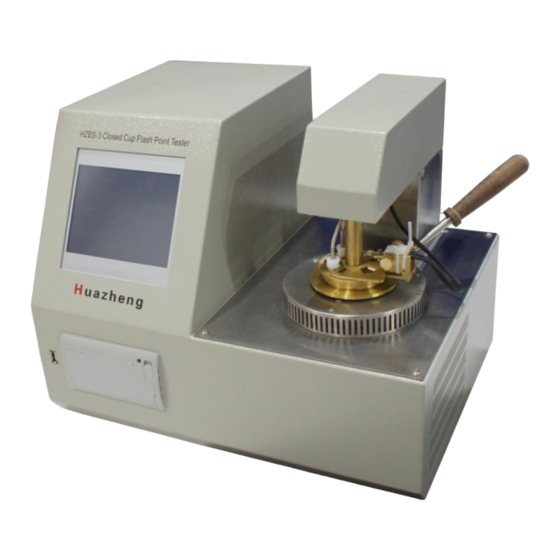
- Page 1 HZBS-3 Closed Cup Flash Point Tester Huazheng Electric Manufacturing (Baoding) Co., Ltd...
- Page 2 (0312) 6775656 to tell you to ser ve you at all times- Baoding Huazheng Elect ric Manufact uring Co. , Lt d. , our company will def initely make you satisf ied !
- Page 3 Safety Instructions 1.Be sure to use a grounded outlet for the instrument’s power supply. 2.No touching the Oil Cups and its nearby parts during test, in case of scald. 3.There must be someone on duty during the test. Cover oil cup lid in time if the sample is burning after the test is completed.
-
Page 4: Table Of Contents
Contents I. Main functions and features......................1 II.Working principle...........................1 III. Main Technical index......................... 2 IV. Instrument Structure And Installation..................3 V. Usage And Operation Procedures................... 3 VI. Precautions And Instrument Maintenance................15 VII. Failure And Treatment......................15 VIII. Packing List..........................16... -
Page 5: Main Functions And Features
I. Main functions and features HZBS-3 Closed Cup Flash Point Tester, color touch screen instead of keyboard operation. Used to determine the closed flash point value of petroleum products. Adopt advanced foreign technology, convenient and fast, open, fuzzy control integrated software, modular structure, in line with national standards, the United States and other standards. -
Page 6: Main Technical Index
temperature rises at a certain rate. Automatic control of ignition and flash detection; When the flash is measured, the system stops data collection, displays the flash temperature, prints the recording results, and stops heating. III. Main Technical index Temperature Measurement Temperature measuring range: -49.9°C ~... -
Page 7: Instrument Structure And Installation
IV. Instrument Structure And Installation 1) Instrument Installation Unpack the instrument and make sure that the equipment is in good condition. Check instrument model and all accessories according to the packing list. C. Please debug the instrument after inspection step 1 & 2. 2) Starting-up Preparation Connect the instrument to the AC 220V power supply;... - Page 8 FIG. 5-1 starting interface diagram Press "skip self-check" to enter the main interface of the instrument, as shown in figure 5-2. ②、Main interface screen of the instrument: Figure 5-2 Main interface diagram of the instrument Press the "instrument self-inspection" button to enter the device self-inspection screen, as shown in figure 5-3.
- Page 9 Press the "experimental parameter setting" button to enter the function screen of parameter setting, as shown in figure 5-5. Press "test flash measurement" button to enter the function screen of flash point measurement, as shown in figure 5-7. Press“the data browse and query”button to enter the historical data query screen, as shown in figure 5-11.
- Page 10 FIG. 5-4 Cup cap test Press the "up", "down", "stop" and "return" keys, and the instrument will respectively carry out the operations of lifting the cup cap, lowering the cup cap, stopping the lifting and returning. Other self-check items can be operated according to the prompt interface. ④、Function screen of Parameter setting:...
- Page 11 FIG. 5-5 Parameter setting Touch with your finger (or with a touch pen) the item you want to modify;Click on the time screen to bring up screen 5-6.
- Page 12 FIG 5-6 modification time Enter the time of year, month, and day in order. Click "OK" to complete the time change. Otherwise, click "ESC" to return. Click automatic printing directly to change the printing mode, that is, whether to automatically print the experimental results after the end of the experiment.
- Page 13 FIG 5-7 Parameter setting of Test setting ◆Touch with the finger (or with the touch pen) the corresponding parameter display box to change the corresponding parameters. When clicking the sample method, enter the test standard selection screen. Figure 5-8.
- Page 14 FIG 5-8 Current standard selection You can choose “custom”, set various parameters according to your own needs, and click “OK” save Settings. Such as picture 5- 9.
- Page 15 FIG 5-9 Custom parameter setting ◆Parameter setting is completed, and return to screen 5-7 sample test parameter setting interface. Press the button of "Cup cap rising", take out the sample cup and put in the oil sample, press the button of "Cup cap falling" to drop the lid to prepare the test, press the button of "test", and the instrument starts to determine the flash point of oil sample, as shown in fig.5-10.
- Page 16 FIG 5-10 Sample testing In the state of trying to fire, the button is invalid, and in other states the button is valid. After the successful test, the instrument displays the test results as shown in figure 5-11.
- Page 17 FIG 5-11 Test result Click the "Cool" button to open the cover of the instrument for heat dissipation. If the test is not successful, the corresponding error prompt window will pop up, and then the interface as shown in figure 5-10 will be displayed. Click to “Cool”,the cooling process needs to be stopped manually.
- Page 18 standard, and displays it in the test screen. ⑥、Date Browsing screen: The instrument keeps 50 groups of test data recently measured, and data records are shown in FIG. 5-12. FIG 5-12 Test result screen Press "page up" and "page down" to view records; Press the "print" button to print the record through the instrument's mini-printer.
-
Page 19: Precautions And Instrument Maintenance
FIG 5-13 No data screen VI. Precautions And Instrument Maintenance The instrument should be used in a non-corrosive environment. The oil cup should be cleaned, when replacing test sample. Check thermocouple should not have oil contamination, or it will affect the detection sensitivity. -
Page 20: Packing List
Remove the lifting arm top cover, and check Large repeatability error 1. whether the mixer shaft is broken, replace the mixer shaft for sample testing 2. Oil may effect on thermocouple sensitivity, plz dry it by filter paper No heating Replaced Electric wire 1.
Need help?
Do you have a question about the HZBS-3 and is the answer not in the manual?
Questions and answers