
Related Manuals for Huazheng HZ-5100S


Summary of Contents for Huazheng HZ-5100S
- Page 1 HZ-5100S Portable Contact Resistance Tester Huazheng Electric Manufacturing (Baoding) Co., Ltd...
- Page 2 (0312) 6775656 to tell you to serve you at all times- Baoding Huazheng Elect ric Manufact ur ing Co. , Lt d. , our company will def initely make you satisf ied !
- Page 3 Important Note If the instrument is not in use, please turn off the power in time. If the instrument is not used for a long time, please charge and discharge regularly. Batteries should be charged and discharged at least once a month. It is strictly forbidden to use power shortage, which will severely shorten the battery life and even make the battery scrap.
-
Page 5: Table Of Contents
Contents I.Introduction.............................1 II.Packaging Content........................1 III.Features............................1 IV.Technical Index..........................2 V.Adjust The Wristband........................3 VI.Battery Charging.........................3 VII.Tilt Hand-held Tester.........................3 VIII.Product Appearance........................ 4 IX.Operation Instructions....................... 5... -
Page 7: I.introduction
I.Introduction The hand-held Circuit resistance tester is an innovative product. The product is compact, hand-held operation, battery power supply, easy to carry. The product is mainly used in the measurement of contact resistance and other micro-Euclidean resistance of switch contacts. The test speed is fast and the accuracy is high. -
Page 8: Iv.technical Index
reach 2000μΩ. Has the open circuit protection, overheating protection and so on perfect protection function. 5. 6 inch super-industrial-grade high-brightness color LCD screen, in strong sunlight display is still clearly visible. Equipped with external printer, easy to print data. ... -
Page 9: V.adjust The Wristband
V.Adjust The Wristband For better grip, strip the belt and adjust the adhesive tape as shown in the following figure. VI.Battery Charging When the battery is low after long storage or before the first use of the hand-held device, please use the charger attached to it to charge the battery for at least 3 hours, and continue to use the hand-held tester when charging. -
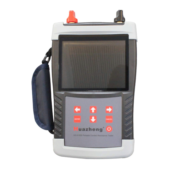
Page 10: Viii.product Appearance
VIII.Product Appearance Top view Front View Side View Function Instructions module I+、 I- Current output terminal, maximum output 100A. U+、U- Voltage input jack, maximum input 5V. 5.6 inch large industrial high brightness color LCD screen, display Display operation menu and test results. Operate instruments. -
Page 11: Ix.operation Instructions
interface Charging Use instrument charger to recharge interface External USB disk is used to store test data, please use FAT or USB interface FAT32 format U disk; in the storage process, it is strictly prohibited to dial out the USB disk. IX.Operation Instructions ... - Page 12 Printer change paper: take out the rotating spanner and open the paper cover; Load the printer paper and pull out a piece of printer paper (tear the teeth out a little bit). Close the cover and press the print head to the print head.
- Page 13 Set date and time of the instrument. Need a password operation, it is not open to the user SV:Display software current version number; HV:Display hardware current version number. Select "Circuit Test" and press "Enter" to enter "Circuit Test" screen, as shown below. Instruction Parameter setting area.
- Page 14 The output current of this test can be set at 30A/50A/80A/100A. If the circuit resistance exceeds the range of the corresponding gear measurement, the current may not reach the set current. The low Current resistance test line matched with the instrument should be used in the test, and the connecting pole should be tightened and the test clamp clamped to reduce the lead resistance.
- Page 15 Instruction Continue to measure the circuit resistance according to the current setting parameters. Print the current test results by connecting the external printer. Save the current test results to the local computer or save it to the external USB disk. Tip: the data saved to the USB is in WORD format, and can be directly edited or printed with OFFICE.
Need help?
Do you have a question about the HZ-5100S and is the answer not in the manual?
Questions and answers