
Subscribe to Our Youtube Channel
Related Manuals for GIGAIPC QBiX-TGLA1135G7-A1


Summary of Contents for GIGAIPC QBiX-TGLA1135G7-A1
-
Page 1: Qbix Industrial Embedded System
QBiX-TGLA1135G7-A1/ QBiX-TGLA1115G4E-A1 QBiX Industrial Embedded System Quick Start Guide www.gigaipc.com... -
Page 2: Copyright Notice
While reasonable efforts have been made in the preparation of this document to assure its accuracy, GIGAIPC assumes no liabilities resulting from errors or omissions in this document, or from the use of the information contained herein. -
Page 3: Acknowledgement
Core, Atom are trademarks of Intel Corporation • • ITE is a trademark of Integrated Technology Express, Inc. IBM, PC/AT, PS/2, and VGA are trademarks of International Business • Machines Corporation. All other product names or trademarks are properties of their respective owners. www.gigaipc.com... -
Page 4: Packing List
Item Quantity System kit 19.5V / 135W adapter Power cord (May vary based on local distribution) Wall Mount Bracket If any of these items are missing or damaged, please contact your distributor or sales representative immediately. www.gigaipc.com... -
Page 5: About This Document
(if any), its specifications, dimensions, jumper/ connector settings/definitions, and driver installation instructions (if any), to facilitate users in setting up their product. Users may refer to the GIGAIPC.com for the latest version of this document. www.gigaipc.com... -
Page 6: Safety Precautions
Make sure the device is installed near a power outlet and is easily accessible. 10. Keep this device away from humidity. 11. Place the device on a solid surface during installation to prevent falls 12. Do not cover the openings on the device to ensure optimal heat dissipation. www.gigaipc.com... - Page 7 19. D O N O T L E AV E T H I S D E V I C E I N A N U N C O N T R O L L E D ENVIRONMENT WITH TEMPERATURES BEYOND THE DEVICE’S PERMITTED STORAGE TEMPERATURES (SEE CHAPTER 1) TO PREVENT DAMAGE. www.gigaipc.com...
-
Page 8: Fcc Statement
Il y a un risque d’explosion si la batterie est remplacée de façon incorrecte. Ne la remplacer qu’avec le même modèle ou équivalent recommandé par le constructeur. Recycler les batteries usées en accord avec les instructions du fabricant et les directives gouvernementales de recyclage. www.gigaipc.com... -
Page 9: Table Of Contents
(Wireless Module inclusion may vary based on local distribution) ..............20 B) Memory Installation: DDR4 SO-DIMM ....21 Antenna Installation (Antenna inclusion may vary based on local distribution) ............ 22 RAL ................23 Support ................ 24 Safety and Regulatory Information ....... 25 www.gigaipc.com... - Page 10 3.2.15 USB31_1 (USB 3.2 Gen 2x1 connector) ......44 3.2.16 HDMI_21 (HDMI connector) ......... 45 3.2.17 LAN1, LAN2 (GbE LAN port connector) ......46 Chapter 4 – BIOS Introduction ..............48 The Main Menu............. 49 Advanced ..............50 4.3.1 TPM Configuration ............51 www.gigaipc.com...
- Page 11 4.3.6 S5 RTC Wake Settings ........... 57 4.3.7 Network Stack Configuration ........58 4.3.8 NVMe Configuration ............. 59 4.3.9 Offboard SATA Controller Configuration ...... 60 Chipset ................61 Security ................. 62 Boot ................65 Save & Exit ..............66 www.gigaipc.com...
-
Page 12: Chapter 1 - Product Specifications
Chapter 1 Chapter 1 - Product Specifications www.gigaipc.com... - Page 13 70.5 20.2 118.0 74.5 133.4 5.25 107.5 12.7 92.6 80.0 11.0 96.0 www.gigaipc.com...
-
Page 14: Specifications
Specifications QBiX-TGLA1135G7-A1 QBiX-TGLA1115G4E-A1 (QB-1135A) (QB-1115A) Dimension System Size : 138W x 118D x 74.2H (mm) Intel® Core™ i3-1115G4E Intel® Core™ i5-1135G7 Processor Processor 10nm SuperFin, 4 cores, 10nm SuperFin, 2 cores, 8 threads, up to 4.2 GHz 4 threads, up to 3.90 GHz Chipset 2 x DDR4 SO-DIMM socket, Max. - Page 15 QBiX-TGLA1135G7-A1 QBiX-TGLA1115G4E-A1 (QB-1135A) (QB-1115A) Operating temperature: 0°C to 50°C Operating humidity: 0-90% (non-condensing) Operation Non-operating temperature:-40°C to 85°C temperature Non-operating humidity: 0%-95% (non-condensing) Use wide temperature range memory and storage Operation: Vibration IEC 60068-2-64, 3 Grms, random, 5 ~ 500 Hz, 1 hr / Per Axis, With...
-
Page 16: Chapter 2 - Qbix Industrial Embedded System Kit
Chapter 2 Chapter 2 – QBiX Industrial Embedded System Kit www.gigaipc.com... -
Page 17: Dimension
Dimension 70.5 20.2 118.0 74.5 133.4 5.25 107.5 12.7 92.6 80.0 11.0 96.0 www.gigaipc.com... -
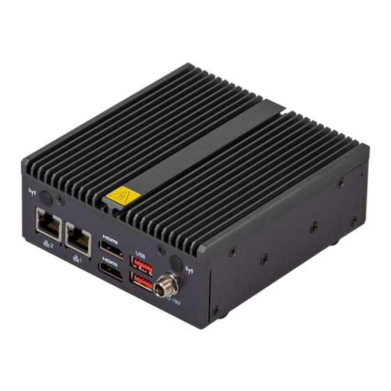
Page 18: Getting Familiar With Your Unit
2 x USB 3.2 Gen 2x1 Screw type DC Jack [Rear Side] WiFi antenna connector (Optional) 1 x COM Port (RS-232/422/485) [Right Side] PWR button with LED 1 x HDD LED 2 x USB 3.2 Gen 2x1 1 x Headphone Jack [Bottom Side] www.gigaipc.com... - Page 19 * Before Connecting the power, make sure to fasten the case securely. * 接上電源前 ,請確實將機殼完整鎖附 。 [Bottom PCB Side] Information 1 x M.2 slot (Support NGFF-2280 SATA/PCIe x4) 1 x M.2 slot (Support NGFF-2230 Wifi/BT) 2 x DDR4 SO-DIMM socket, Max. Capacity 64 GB www.gigaipc.com...
-
Page 20: A) Wireless Module : How To Safely Install The Module (Wireless Module Inclusion May Vary Based On Local Distribution)
Module (Wireless Module inclusion may vary based on local distribution) Carefully insert the wireless module into Lock the screw in the middle. the M.2 slot 鎖入固定於無線模組中央頂端的螺 小心地將無線模組安裝於M.2插槽中。 絲。 青山依舊在,幾度夕陽紅。慣看秋月春風。一 壺濁酒喜相逢,浪花淘盡英雄。是非成敗轉頭 Install the antenna on the left side of the connection wireless module down. 向下安裝連結於無線模組左側頂端天線。 www.gigaipc.com... -
Page 21: B) Memory Installation: Ddr4 So-Dimm
B) Memory Installation: DDR4 SO-DIMM SO-DIMM www.gigaipc.com... -
Page 22: Antenna Installation (Antenna Inclusion May Vary Based On Local Distribution)
Antenna Installation (Antenna inclusion may vary based on local distribution) www.gigaipc.com... -
Page 23: Ral
This equipment is intended to be used in Restrict Access Location. The access can only be gained by Skilled person. Only authorized by well trained professional person can access the restrict access location. www.gigaipc.com... -
Page 24: Support
Support ● For a list of tested memory, M.2, 2.5’’ SSD, wireless adapters and OS supported, go to: http://www.gigaipc.com ● To download the latest drivers and BIOS updates, go to: http://www. gigaipc.com ● For product support, go to: http://www.gigaipc.com www.gigaipc.com... -
Page 25: Safety And Regulatory Information
At the end of its serviceable life, this product should not be treated as household or general waste. It should be handed over to the applicable collection point for the recycling of electrical and electronic equipment, or returned to the supplier for disposal. www.gigaipc.com... -
Page 26: Chapter 3 - Hardware Information
Chapter 3 Chapter 3 – Hardware Information www.gigaipc.com... -
Page 27: Jumpers And Connectors
Jumpers and Connectors www.gigaipc.com... - Page 28 Code Description ATX_IN ATX IN Connector BATTERY Battery Connector E-key, Supports NGFF-2230 (WiFi/BT) M-key, SATA 6.0 Gb/s, PCIe x4, Supports NGFF- 2280 card F_USB2 USB 2.0 header Front panel header F_PANEL ME Enable jumper TPM header www.gigaipc.com...
- Page 29 CPU FAN Connector COM1 Serial port connector (RS-232/422/485) USB31_2 USB 3.2 Gen 2x1 Port x 2 DC_IN Screw type DC Jack USB31_1 USB 3.2 Gen 2x1 Port x 2 HDMI_21 HDMI Port LAN2 GbE LAN Port LAN1 GbE LAN Port www.gigaipc.com...
-
Page 30: Atx_In (Atx In Connector)
3.2.1 ATX_IN (ATX IN Connector) Pin 1 ATX IN Connector Connector PN Vendor 99-01740-B004-A TCONN Pin No. Definition DC IN www.gigaipc.com... -
Page 31: Battery (Battery Connector)
3.2.2 BATTERY (Battery connector) Pin 1 Battery Connector Pin No. Definition www.gigaipc.com... -
Page 32: M2E (E-Key, Supports Ngff-2230 (Wifi/Bt) Slot)
M.2 E Key Connector WLAN_RXn CL_Clock Clock_Dp Clock_Dn SUSCLK Clock_ Pin No. Definition Pin No. Definition PLT_Reset Request PCIE_Wake up BT_Disable USB_D+ WIFI_Disable USB_D- BT_WAKE Connector PN Vendor Pin No. Definition Pin No. Definition 80152-4221 BELLWETHER WLAN_TXp WLAN_TXn CL_Reset www.gigaipc.com... -
Page 33: M2M (M-Key, Supports Ngff-2280 (Pcie X4, Sata 6Gb/S)
Pin No. Definition Pin No. Definition 3.3V SATA_TXn 3.3V SATA_TXp PLT_Reset CK_Request Clock_n PCIE_Wake up M2_LED Clock_p 3.3V 3.3V Pin No. Definition Pin No. Definition 3.3V SUSCLK 3.3V M2_SSD_ 3.3V Detect 3.3V 3.3V PCIE_RXn Connector PN Vendor PCIE_RXp 2E0BC41-C85CM-LH FOXCONN www.gigaipc.com... -
Page 34: F_Usb2 (Usb 2.0 Header)
3.2.5 F_USB2 (USB 2.0 header) Pin 1 USB 2.0 header Connector PN Vendor A1250WV-S- JOINT-TECH 04PNLBT1T00L 50273-0047N-001 ACES F_USB2.0 Pin No. Definition D- (USBN) D+ (USBP) www.gigaipc.com... -
Page 35: F_Panel (Front Panel Connector)
3.2.6 F_PANEL (Front panel Connector) Pin 1 Front Panel Connector Connector PN Vendor 87216-1206-06 ACES Pin No. Definition SATA_LED_P (3.3V) MPD+ MPD- Panshw_D PMU_RSTBTN_N_D 3.3V www.gigaipc.com... -
Page 36: Me (Me Enable Jumper)
3.2.7 ME (ME Enable jumper) Pin 1 ME Enable jumper ME Enable Jumper Enable Disable www.gigaipc.com... -
Page 37: Tpm (Tpm Header)
3.2.8 TPM (TPM header) Pin 1 TPM header Connector PN Vendor 87216-1004-06 ACES ※Note : TPM module must be SPI interface. Pin No. Definition Clock SPI_CS# SPI_SO SPI_RST# SPI_SI 3.3V www.gigaipc.com... -
Page 38: Fp_Audio (Front Panel Audio Header)
3.2.9 FP_AUDIO (Front panel audio header) Pin 1 Front panel audio header Connector PN Vendor 725-81-10TW00 PINREX A2004WV-2X05P46 JOINT-TECH Definition Definition MIC_Left MIC_Right MIC_JD_ HP_Right SENSE FAUDIO_JD_C HP_JD_ HP_Left SENSE www.gigaipc.com... -
Page 39: Sodimm1, Sodimm2 (Ddr4 So-Dimm Slot)
3.2.10 SODIMM1, SODIMM2 (DDR4 SO-DIMM Slot) www.gigaipc.com... -
Page 40: Cpu Fan (Cpu Fan Connector)
3.2.11 CPU FAN (CPU FAN connector) Pin 1 CPU FAN connector Connector PN Vendor 85205-0470N ACES A1250WV-S-04PC JOINT-TECH Pin No. Definition Detect Speed Control www.gigaipc.com... -
Page 41: Com1 (Serial Port Connector, Rs-232/422/485)
3.2.12 COM1 (Serial port connector, RS-232/422/485) Serial port Connector Connector PN Vendor SM41D1P1122N33N1 FENYING Pin No. RS-232 RS-422 RS-485 Full Duplex Half Duplex TXD- TXD+ RXD+ – RXD- – – – – – – – – – www.gigaipc.com... -
Page 42: Usb31_2 (Usb 3.2 Gen 2X1 Port)
3.2.13 USB31_2 (USB 3.2 Gen 2x1 Port) USB 3.2 Gen 2x1 connector Connector PN Vendor 18-A5950-6A33-A TCONN Definition Definition USB_D- USB_D- USB_D+ USB_D+ USB3_RX- USB3_RX- USB3_RX+ USB3_RX+ USB3_TX- USB3_TX- USB3_TX+ USB3_TX+ www.gigaipc.com... -
Page 43: Dc_In (Screw Type Dc Jack Connector)
3.2.14 DC_IN (Screw type DC Jack connector) Screw Type DC Jack Connector Connector PN Vendor 655-360-000 SHEN-MING www.gigaipc.com... -
Page 44: Usb31_1 (Usb 3.2 Gen 2X1 Connector)
3.2.15 USB31_1 (USB 3.2 Gen 2x1 connector) USB 3.2 Gen 2x1 connector Connector PN Vendor 18-A5950-6A33-A TCONN Definition Definition USB_D- USB_D- USB_D+ USB_D+ USB3_RX- USB3_RX- USB3_RX+ USB3_RX+ USB3_TX- USB3_TX- USB3_TX+ USB3_TX+ www.gigaipc.com... -
Page 45: Hdmi_21 (Hdmi Connector)
3.2.16 HDMI_21 (HDMI connector) HDMI Connector Connector PN Vendor QJ11191-DFB1-4F FOXCONN Pin No. Definition Pin No. Definition HDMI_D2+ HDMI_CLK- HDMI_D2- HDMI_D1+ HDMI_SCL HDMI_D1- HDMI_SDA HDMI_D0+ HDMI_D0- HDMI_HPD HDMI_CLK+ www.gigaipc.com... -
Page 46: Lan1, Lan2 (Gbe Lan Port Connector)
LAN Connector State Description Orange On 1Gbps data rate Green On 100Mbps data rate 10Mbps data rate Link / Connection/ Activity LED Speed LED Pin No. Definition Connector PN Vendor TX+_D1 RT7-GB-0003 TX-_D1 RX+_D2 BI+_D3 BI-_D3 RX-_D2 BI+_D4 BI-_D4 www.gigaipc.com... -
Page 47: Chapter 4 - Bios
Chapter 4 Chapter 4 – BIOS www.gigaipc.com... -
Page 48: Introduction
Execute command or enter the submenu Increase the numeric value or make + changes Decrease the numeric value or make – changes General Help Previous Values Load Optimized Defaults Settings Save changes & Exit the BIOS Setup program Exit the BIOS Setup program www.gigaipc.com... -
Page 49: The Main Menu
ME FW version Shows ME firmware version Set the Date for the system System Date (Format : Week - Month - Day - Year) Set the time for the system System Time (Format : Hour - Minute - Second) www.gigaipc.com... -
Page 50: Advanced
Advanced The Advanced menu is to configure the functions of hardware settings through submenu. Use arrow keys to move among the items, and press <Enter> to access into the related submenu. www.gigaipc.com... -
Page 51: Tpm Configuration
4.3.1 TPM Configuration Use TPM Configuration submenu to choose TPM interface. Item Description PTT : Internal TPM (Default setting) TPM Device dTPM : External TPM (When using External TPM module or Selection having TPM chip on MB) www.gigaipc.com... - Page 52 Trusted Computing : Shows TPM information, and TPM module configuration setting. Item Description Security Device Enabled : Enables TPM feature (Default setting) support Disabled : Disables TPM feature www.gigaipc.com...
-
Page 53: Sata And Rst Configuration
4.3.2 SATA And RST Configuration Item Description shows M.2 SSD information www.gigaipc.com... -
Page 54: Cpu Configuration
Intel(R) Speed Shift To speed up CPU frequency transition time from basic frequency to maximum frequency. Technology Interrupt Enabled : Enables Intel(R) Speed Shift Technology Interrupt control (Default setting) Control Disabled : Disables Intel(R) Speed Shift Technology Interrupt control www.gigaipc.com... -
Page 55: Super Io Configuration
Enabled : Enables Serial Port function (Default setting) Disabled : Disables Serial Port function Serial Port 1 Configuration Device settings : Display the specified Serial Port base I/O address and IRQ COM Port Mode : Choose RS-232, RS-422, or RS-485 feature www.gigaipc.com... -
Page 56: Hardware Monitor
4.3.5 Hardware Monitor Item Description CPU Temperature Shows current CPU temperature System Temperature Shows current system temperature www.gigaipc.com... -
Page 57: S5 Rtc Wake Settings
Enable or Disable System to wake on a specific time. Wake system Disabled : Disables system to wake on a specific time (Default setting) from S5 Fixed Time : Enables system to wake on a specific time (Format : hr : min : sec) www.gigaipc.com... -
Page 58: Network Stack Configuration
When Network stack is enabled : Ipv4 PXE Support Disabled : Disables Ipv4 PXE Support Enabled : Enables Ipv4 PXE Support When Network stack is enabled : Ipv6 PXE Support Disabled : Disables Ipv6 PXE Support Enabled : Enables Ipv6 PXE Support www.gigaipc.com... -
Page 59: Nvme Configuration
4.3.8 NVMe Configuration NVMe Configuration shows information when your M.2 NVMe PCIe SSD is installed. www.gigaipc.com... -
Page 60: Offboard Sata Controller Configuration
4.3.9 Offboard SATA Controller Configuration www.gigaipc.com... -
Page 61: Chipset
Enable/Disable Watchdog Timer function Watchdog Timer Enabled : Enables Watchdog Timer function Disabled : Disabled Watchdog Timer function (Default setting) Enable/Disable BIOS Lock function BIOS Lock Enabled : Enables BIOS Lock function (Default setting) Disabled : Disabled BIOS Lock funtion www.gigaipc.com... -
Page 62: Security
To set up Administrator's password Administrator Minimum length : 3 Password Maximum length : 20 To set up User's password User Password Minimum length : 3 Maximum length : 20 Secure Boot Press <Enter> to configure the advanced items www.gigaipc.com... - Page 63 No : Cancel to restore factory settings Reset To Setup Yes : Agree to setup mode Mode No : Cancel to setup mode Enables expert users to modify Secure boot policy variables without full Key Management authentication Press <Enter> to configure the advanced items www.gigaipc.com...
- Page 64 Boot mode Signatures Remove 'UEFI CA' To remove 'UEFI CA' from database from DB Restore DB variables to fac tor y Restore DB defaults defaults Yes : Agree to restore DB defaults No : Cancel to restore DB defaults www.gigaipc.com...
-
Page 65: Boot
Enabled : Enables Full screen LOGO Show on POST screen LOGO Show Disabled : Disables Full screen LOGO Show on POST screen (Default setting) Boot Option #1 Shows the information of the storage that be installed in the system Boot Option #2 Choose/set the boot priority www.gigaipc.com... -
Page 66: Save & Exit
Yes : Agree to load optimized defaults No : Cancel to load optimized defaults Enable/Disable Me FW image re-flash function Me FW Image Enabled : Enables Me FW image re-flash function Re-Flahs Disabled : Disables Me FW image re-flash function (Default setting) www.gigaipc.com...
Need help?
Do you have a question about the QBiX-TGLA1135G7-A1 and is the answer not in the manual?
Questions and answers