Table of Contents
Advertisement
Available languages
Available languages
Quick Links
Betriebsanleitung
Operating Instruction
Lubo-DryExx
Advanced
®
®
System für die Dosierung von
DryExx
- Bandschmierprodukten mit Steuerung
®
DryExx
Advanced
für bis zu 16 Schmierkreise in 10 Anlagen.
®
Application System for
DryExx
- Conveyor Belt Lubrication Products with Control
®
System
DryExx
Advanced
for 16 lubricant circuits in 10 plants.
Deutsch
English
417101634_Lubo-DryExx_Advanced
- 1 -
Rev. 07-01.15
Advertisement
Chapters
Table of Contents

Related Manuals for Ecolab Lubo-DryExx


Summary of Contents for Ecolab Lubo-DryExx
- Page 1 Betriebsanleitung Operating Instruction Lubo-DryExx Advanced ® ® System für die Dosierung von DryExx - Bandschmierprodukten mit Steuerung ® DryExx Advanced für bis zu 16 Schmierkreise in 10 Anlagen. ® Application System for DryExx - Conveyor Belt Lubrication Products with Control ®...
-
Page 2: Table Of Contents
Elektrischer Anschluss Chemischer Anschluss Befüllen des Verteilerleitungssystems Automatikbetrieb Gebindewechsel Ersatzteile Wartung 10.1 Wartungshinweis 10.2 Wartungsarbeiten Störungsüberprüfung Technische Daten ® 12.1 Lubo-DryExx - Hardware ® ® 12.2 Lubo-DryExx – Steuerung DryExx Advanced Konformitätserklärungen ® 13.1 Lubo-DryExx - Hardware ® ® 13.2... -
Page 3: Allgemeines
Fachpersonal durchgeführt werden. VORSICHT Bei allen Wartungs- und Reparaturarbeiten ist geeignete Schutzkleidung zu tragen. Kontaktadresse / Hersteller Ecolab Engineering GmbH Raiffeisenstraße 7 D-83309 Siegsdorf Telefon (+49) 86 62 / 61-0 Telefax (+49) 86 62 / 61-166 eMail: engineering-mailbox@ecolab.com... -
Page 4: Sicherheit
Sicherheit Allgemeines Anschluss-, Wartungs-, und Reparaturarbeiten dürfen nur von qualifiziertem Fachpersonal am abgeschalteten (Netzstecker ziehen!) und druckfreien Gerät durchgeführt werden. Hervorhebungen Die hier dargestellten Hervorhebungen haben folgende Bedeutung: wird benutzt, wenn ungenaues Befolgen oder Nichtbefolgen von Bedienungs- VORSICHT Anweisungen, Arbeitsanweisungen, vorgeschriebenen Arbeitsabläufen und dergleichen zu Verletzungen oder Unfällen führen kann. -
Page 5: Lieferumfang
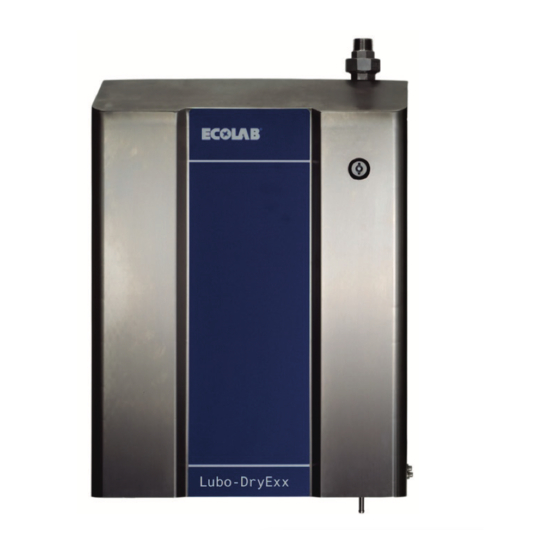
Lieferumfang Dosierstation ® Lubo-DryExx Abb. 3.1 Art. Nr. 182830 Art. Nr. 182831 Steuerung ® DryExx Advanced Abb. 3.2 Art. Nr. 182837 Betriebsanleitung ® Lubo-DryExx Advanced Abb. 3.3 Art. Nr. 417101634 417101634_Lubo-DryExx_Advanced - 5 - Rev. 07-01.15... -
Page 6: Funktionsbeschreibung
Funktionsbeschreibung ® Die Dosierstationen Lubo-DryExx sind Geräte zur automatischen Versorgung von ® DryExx - Bandschmieranlagen mit Bandschmiermittel. ® Beschreibung System DryExx ® DryExx System besteht im Wesentlichen aus Dosierstation mit einer Druckluftmembranpumpe, einer Steuereinheit sowie dem Standard Leitungs- und Düsensystem. Für die Steuerung stehen je nach Anlagengröße bzw. –spezifikation verschiedene Typen zur Auswahl. -
Page 7: Beschreibung Schmierfunktion
Beschreibung Schmierfunktion Bei Aktivierung eines Schmierkreises wird eine Druckluftmembranpumpe gestartet und der Druck des Bandschmiermittels im Leitungssystem erhöht. Nach der fest eingestellten Vorlaufzeit wird das Schmierkreisventil für eine einstellbare Zeit geöffnet und das Bandschmierprodukt über das Düsensystem auf die Transportbandketten aufgebracht. Der notwendige Produktdruck wird mittels des Druckluftfilterreglers in der Dosierstation eingestellt. -
Page 8: Übersicht: Steuerungen Für Dryexx ® Systeme
® Übersicht: Steuerungen für DryExx Systeme ® 4.5.1 DryExx Small ® als einfache Variante für kleinere DryExx Anlagen bis zu 6 Schmierkreisen. Die Steuerung basiert auf einer Unitronics JAZZ! und ist in ein Kunststoffgehäuse integriert. Eine Betriebsstundenerfassung aller Schmierkreise ist möglich. ®... -
Page 9: Dryexx ® Universal
Systemen mit bis zu 48 Schmier- und Reinigungskreisen an 3 Dosierstationen bei ® vollständigem Ausbau. Die Steuerung DryExx Universal arbeitet ausschließlich mit ® unseren Dosierstationen „Lubo-DryExx “ zusammen. ® 4.5.7 DryExx Venture ® wird projektbezogen gefertigt und ist für DryExx Systeme mit speziellen Anforderungen z.B. -
Page 10: Montage
Montage ® DryExx - Dosierstationen werden im Herstellerwerk vormontiert und sind bei Lieferung anschlussfertig und zur Wandmontage vorbereitet. ® Die Dosierstationen sind ausschließlich mit einer DryExx - Steuerung zu betreiben und erhalten auch von dieser die Spannungsversorgung. 417101634_Lubo-DryExx_Advanced - 10 - Rev. -
Page 11: Anschluss
Anschluss ® Anschlussübersicht: DryExx Gerätetyp 182830 Gerätetyp 182831 Abb. 6.1 Abb. 6.2 Bezeichnung Verbraucheranschluss, R ¾“ 3/2-Wege-Magnetventil, Vorsteuerventil 2/2-Wege-Membranventil, pneumatisch gesteuert Rücklaufanschluss für Schlauch 12/21 Produktanschluss Druckseite Produktanschluss über Sauglanze Druckluft-Membranpumpe Druckluftanschluss Dosierpumpe Druckluftfilterregler Druckluftanschluss, 8/6 3/2-Wege-Magnetventil, Steuerventil Pumpe ® Wandmontage: DryExx Zur Wandbefestigung sind folgende Teile... -
Page 12: Steuerung Dryexx ® Advanced
„7.3.8.1.2.1 Ventilzuordnung“ beschrieben, vorgenommen werden. Ist die Ventilzuordnung nicht erfolgt, dann sind die Parametersätze nicht zugänglich. • Jedes Ventil darf nur 1x zugeordnet werden. • Im Auslieferzustand sind folgende Passwörter vergeben: Ecolab 7777 Kunde 5555 Bediener 3333 • Im Zuge der Erstkonfiguration müssen die Passwörter nach den Kundenvorgaben entsprechend Punkt „Passwort“... -
Page 13: Visualisierungen (Displayansichten)
Visualisierungen (Displayansichten) 7.3.1 Grundbild / Startbild Abb. 7.1 Erscheint nach Netz „EIN“ im Grundbild wird gezeigt: • Aktuelles Datum und Uhrzeit des Systems • Zugangsbutton zu den einzelnen Menüs • Aktive Alarme in der Meldezeile am oberen Rand des Displays 7.3.2 Statistik Abb. - Page 14 7.3.3.1 Archivauswahl • Sprung zum Menü “Tagesarchiv” Abb. 7.5 Drücken des Buttons "Aktueller Tag" • Sprung zum Menü “Monatsarchiv” Drücken des Buttons "Aktueller Monat“ • Sprung zum Menü “Jahresarchiv“ Drücken des Buttons „Jahresarchiv“, nachdem zuvor die Auswahl des gewünschten Monats (über Auswahlfeld unter „Jahresarchiv) erfolgte •...
-
Page 15: Parameter Kreise
7.3.3.1.1.1.1 Archivanzeige Das Bild enthält folgende Anzeigen Abb. 7.8 • Kreis Nummer • Anlagen Nummer • Laufende Nummer des Ventils • Gewähltes Archiv • Verbrauchswerte • Zum Verlassen des Bildes “ Archiv Kreis xx Drücken der Taste "ESC" ODER •... - Page 16 7.3.4.1.1.1 Parameteranzeige: Ändern der Dosier- und Booster-Zeiten Das Bild enthält die Anzeige für: Abb. 7.12 • Kreis und Anlagen Nummer (Bereich) • Laufende Nummer des Ventils im System • Takt- und Pausenzeit (Soll und Ist) • Aktueller Zustand „Booster“ • Aktueller Zustand der Freigabe •...
-
Page 17: Meldungen
7.3.4.1.1.3 Parameter: Separate Boosterfunktion Das Bild enthält die Anzeige für: Abb. 7.14 • Kreis und Anlagen Nummer (Bereich) • Laufende Nummer des Ventils im System • Wartezeit bis zur Aktivierung (Soll und Ist) Zeit nach der die Booster-Funktion aktiv wird ... -
Page 18: Logout
7.3.5.1 Meldungsanzeige Abb. 7.16 Folgende Meldungen werden angezeigt Störmeldungen (müssen mit quittiert werden) Betriebsmeldungen HMI-Systemmeldungen Diagnoseereignisse Zum Scrollen in den Meldungen Benutzen der Scollbalken Zum verlassen des Bildes Drücken des Buttons "zurück" 7.3.6 Logout Abb. - Page 19 7.3.7.1.1 Betriebsarten Das Bild enthält folgende Anzeigen Abb. 7.20 • Aktive Betriebsart • Zum ändern der Betriebsart Wahl der gewünschten Betriebsart durch drücken des zugehörigen Buttons Einschalten der Dosiermengen-Überwachung • Zum Verlassen des Bildes “Betriebsart“ Drücken des Buttons "zurück" ODER •...
-
Page 20: Systemeinstellungen
7.3.8 Systemeinstellungen Abb. 7.23 • Sprung zum Bild “Systemeinstellungen” Drücken des Buttons "Ecolab" 7.3.8.1 Systemmenü • Sprung zu den Untermenüs Abb. 7.24 Drücken des gewünschten Buttons • Sprachumschaltung (zyklisch) Drücken des Button „Sprache“ • Zum Verlassen des Bildes “Systemeinstellungen“... - Page 21 7.3.8.1.2.1 Ventilzuordnung • Zum Festlegen der Zuordnung Abb. 7.27 Drücken des entsprechenden Buttons „V xx“/ „Anlage xx“ • Sprung zum Bild „Ventilzuordnung 2“ Drücken des Buttons „Ventile 6-10“ • Zum Verlassen des Bildes “ Versionsauswahl“ Drücken des Buttons "zurück" ODER •...
- Page 22 7.3.8.1.3.2 Digitale Eingänge Dieses Bild zeigt den aktuellen Signalzustand der Abb. 7.30 Eingangsbytes 124-126 • Sprung zum Bild „Eingangsbyte 0/1“ Drücken des Buttons „EB 0/1“ • Zum Verlassen des Bildes “digitale Eingangsbytes“ Drücken des Buttons "zurück" ODER • Sprung zum Bild “Start“ ...
-
Page 23: Inbetriebnahme
Inbetriebnahme ® Nach Abschluss der Montage und Herstellen aller Anschlüsse ist DryExx mit folgenden Schritten in Betrieb zu nehmen. Elektrischer Anschluss Wenn die Dosierstation und die Steuerung nicht bereits ab Werk anschlussfertig auf eine Standkonsole montiert geliefert werden, sind alle elektrischen Anschlüsse ®... -
Page 24: Ersatzteile
Ersatzteile Gerätetyp 182830 Gerätetyp 182831 Abb. 9.1 Abb. 9.2 Typ 182830 & 182831 Bezeichnung Artikel Nr. 3/2-Wege-Magnetventil, NW1,2 PA/NBR, Typ 6012, 24 V/DC, 5W 417704359 2/2-Wege Membranventil, DN 15 PP/EPDM 415502583 Gerätesteckdose Standard, Festo 418468065 Produktanschluss bestehend aus: Sauglanze, l=1125 mm, 12/21 (Zubehör, nicht im Lieferumfang) 288460 Schutzhülse für Sauglanze (Zubehör, nicht im Lieferumfang) 286191... -
Page 25: Wartung
Wartung 10.1 Wartungshinweis Die Dosierstation wird im Herstellerwerk geprüft und befindet sich beim Versand in ordnungsgemäßem und sicherem technischen Zustand. Zur Sicherung dieses Zustands und der des störungsfreien Betriebs muss der Benutzer den Inhalt dieser Bedienungsanleitung aufmerksam lesen. Als wesentliche Voraussetzung ist zu sichern, dass das Gerät vor der Durchführung von VORSICHT Wartungs- und Instandsetzungsarbeiten vom Netz getrennt wird und nicht unter Druck steht. -
Page 26: Störungsüberprüfung
Störungsüberprüfung Störungsbehebungen bei unter Spannung bzw. unter Druck stehenden Leitungen dürfen VORSICHT nur von einer Fachkraft durchgeführt werden. Fehlersymptom Ursache/Störung Behebung Dosierpumpe saugt nicht Siehe Pumpenhandbuch Siehe Pumpenhandbuch Filterdruckregler und 3/2-Wege- Verminderte Luftsteuerleitung bringt zu Magnetventil prüfen Dosierleistung wenig Druck Druckluftzuleitung prüfen Leckagen beseitigen kein Druckaufbau in der... -
Page 27: Technische Daten
Technische Daten ® 12.1 Lubo-DryExx - Hardware Pumpe Druckluft-Membranpumpe Förderleistung 0 - 25 l/min Dosiergegendruck max. 7 bar Luftsteuerdruck max. 7 bar Luftverbrauch ca. 0,2 Nm³/h Anschluss Druckluft 8/6 x 1 / 10/8 x 1 mm Anschluss Bandschmiermittel: saugseitig 12/21 x 4,5 PVC Gewebeschlauch druckseitig R ¾“... -
Page 28: Konformitätserklärungen
Konformitätserklärungen ® 13.1 Lubo-DryExx - Hardware 417101634_Lubo-DryExx_Advanced - 28 - Rev. 07-01.15... -
Page 29: Lubo-Dryexx - Steuerung Dryexx Advanced
® ® 13.2 Lubo-DryExx - Steuerung DryExx Advanced Control Cabinet Art. Nr. 182837 417101634_Lubo-DryExx_Advanced - 29 - Rev. 07-01.15... - Page 30 Automatic Operation Changing the Hopper Reservoir Spare parts Maintenance 10.1 Maintenance Information 10.2 Maintenance Tasks Fault Checking Technical Data ® 12.1 Lubo-DryExx - Hardware ® ® 12.2 Lubo-DryExx – Control System DryExx Advanced Declarations of conformity ® 13.1 Lubo-DryExx - Hardware ®...
-
Page 31: General
Repair and maintenance work may only be carried out by authorised experts. WARNING Suitable protective clothing must be worn during all maintenance and repair work. Contact address / Customer Ecolab Engineering GmbH Raiffeisenstraße 7 D-83309 Siegsdorf Telefon (+49) 86 62 / 61-0... -
Page 32: Safety
Safety General All connection, adjustment, maintenance and repair procedures must be carried out only by qualified professional personnel, with the device switched off (disconnect the mains plug!) and not under pressure. Indications The highlight symbols shown here have the following meanings: means that failure to observe operating instructions, working instructions, required WARNING work sequences etc., or failure to observe these correctly, may cause injuries or... -
Page 33: Scope Of Supply
Scope of supply Metering station ® Lubo-DryExx fig. 3.1 Art. no. 182830 Art. no. 182831 Control System ® DryExx Advanced fig. 3.2 Art. no. 182837 Operating Instruction ® Lubo-DryExx Advanced fig. 3.3 Art. no. 417101634 417101634_Lubo-DryExx_Advanced - 33 - Rev. 07-01.15... -
Page 34: Functional Description
Functional description ® Lubo-DryExx metering stations are equipment for the automatic application of ® DryExx conveyor belt lubrication systems with lubricant. ® Description of DryExx System (Hardware) ® DryExx System consists essentially of an metering station with a diaphragm compressed air pump, a control unit as well as the standard piping and nozzle system. -
Page 35: Lubrication Function Description
Lubrication Function Description When a lubrication circuit is activated a diaphragm compressed air pump is started and the pressure of the conveyor belt lubricant in the system is raised. Following the fixed run up period, the lubrication circuit valve opens for an adjustable period of time and the conveyor belt lubricant is applied via the nozzle system to the conveyor belt tracks. -
Page 36: Overview: System Control For Dryexx ® Systems
DryExx systems with up to 48 lubrication and cleaning circuits on 3 dosing units in the full ® extension state. The DryExx Universal control center operates exclusively with our ® “Lubo-DryExx “ dosing units. 417101634_Lubo-DryExx_Advanced - 36 - Rev. 07-01.15... -
Page 37: Dryexx ® Venture
® 4.5.7 DryExx Venture ® Is tailor made to suit individual systems and is for DryExx systems with special requirements, such as other control unit variants, several metering stations for large installation complexes, etc. For this customer and system requirements can be taken into account. -
Page 38: Assembly
Assembly ® DryExx metering stations are pre-assembled by the manufacturer and are ready for connection and wall mounting on delivery. ® The metering stations are only to be used with a DryExx control unit, through which electrical power must also be supplied. 417101634_Lubo-DryExx_Advanced - 38 - Rev. -
Page 39: Connection
Connection ® Connection Overview: DryExx Unit type 182830 Unit type 182831 fig. 6.1 fig. 6.2 Description User connection, R ¾“ 3/2-Way-Solenoid valve, pre-control valve 2/2-Way-Diaphragm valve, pneumatic controled Return connection for hose 12/21 Lubricant connection, pressure side. Lubricant connection via suction lance Diaphragm compressed air pump Compressed air connection, applicator pump Compressed air filter regulator... -
Page 40: Control System Dryexx Advanced
If you have not carried out valve allocation, you cannot access the parameter sets. • Each valve can only be allocated once. • The following passwords are set when the system is delivered: Ecolab 7777 Customer 5555... -
Page 41: Visualisation
Visualisation 7.3.1 Main screen / Start screen fig. 7.1 This screen appears when you switch the system The main screen displays the following information: • Current date and time of the system • Buttons for accessing the menus • Active alarms (in the notification line at the top of the screen) 7.3.2 Statistics... - Page 42 7.3.3.1 Archive selection • To go to the ‘Daily Archive’ menu fig. 7.5 Press ‘Current Day • To go to the ‘Monthly Archive’ menu: Press ‘Current Month’ • To go to the ‘Yearly Archive’ menu: Press ‘Yearly Archive’ after selecting the required month using the selection field beneath ‘Yearly Archive’...
-
Page 43: Circuit Parameters
7.3.3.1.1.1.1 Archive display This screen displays the following information: fig. 7.8 • Circuit number • System number • Sequential valve number • Selected archive • Consumption values • To leave the ‘Archive for Circuit xx’ screen: Press "ESC" • To go to “Monthly archive part 2 ... - Page 44 7.3.4.1.1.1 Parameter display: Change Valve- and Booster-times The picture shows the following items: fig. 7.12 Circuit and area number (area) Total valve number of the system Pulse- and break-time (default and actual) Actual state of „Booster“ ...
-
Page 45: Messages
7.3.4.1.1.3 Parameter display: Change Separate Booster-function The picture shows the following items: fig. 7.14 Circuit and area number (area) Total valve number of the system Waiting time for activation (default and actual) The time until the Booster-funktion will be activated ... -
Page 46: Logout
7.3.5.1 Message displays fig. 7.16 The following messages are indicated: Fault messages (must be acknowledged) Operating signals HMI-System messages Result of diagnostics Scroll in the messages Use the scroll-bars Leave screen Press "Back" 7.3.6 Logout fig. - Page 47 7.3.7.1.1 Operation modes The display contains the following announcements: fig. 7.20 • Active operation mode • To change operation mode Press desired operation mode button Switch on control dosing amount • To leave “Operation mode“ Press ‘Back’ •...
-
Page 48: 7.3.8.1 System Settings
7.3.8 System settings fig. 7.23 “System settings” • To go to the Press "Ecolab" 7.3.8.1 System settings • To go to sub menues fig. 7.24 Press desired button • To switch language (circular) Press „language/Sprache“ • To leave “System settings“... - Page 49 7.3.8.1.2.1 Valve assignment fig. 7.27 • To appoint the allocation Press desired button „V xx“/ „Area xx“ • To go to „valve assignment 2“ Press „valves 6-10“ • To leave “Valve assignement“ Press ‘Back’ • To go to the ‘Start’ screen: ...
- Page 50 7.3.8.1.3.2 Digital Input fig. 7.30 The display contains the actual signal status of inputbytes 124-126 • To go to the „Inputbyte 0/1“ Press „IB 0/1“ • To leave “digital Inputbyte“ Press ‘Back’ • To go to the ‘Start’ screen: ...
-
Page 51: First Use
First Use ® Following installation and supply of the connections, DryExx the following steps are to be followed to bring it into use: Electrical Connection If the metering station and control unit are not supplied from the factory on a standard console ready for connection, then all electrical connections shown in the connection ®... -
Page 52: Spare Parts
Spare parts unit type 182830 unit type 182831 fig. 9.1 fig. 9.2 Type 182830 & 182831 Description Article no. 3/2 way solenoid valve NW1,2 PA/NBR, type 6012, 24 V/DC, 5W 417704359 2/2 way diapragm valve, DN 15 PP/EPDM 415502583 Standard Festo equipment socket 418468065 Lubricant connection consisting of: Suction lance l=1125 mm, 12/21 (Accessories, not scope of supply) -
Page 53: Maintenance
Maintenance 10.1 Maintenance Information The metering station is tested at the factory and when dispatched is in a technically sound condition and in accordance with the specifications. To maintain this condition, and for trouble free operation, the user must pay careful attention to the content of these instructions. -
Page 54: Fault Checking
Fault Checking The remedying of defects in circuits that are live, or under pressure, should only be WARNING carried out by specialist qualified personnel. Error indication Cause / Fault Remedy No suction at applicator See pump handbook See pump handbook pump Check filter pressure regulator and Reduced applicator... -
Page 55: Technical Data
Technical Data ® 12.1 Lubo-DryExx - Hardware Pump Diaphragm compressed air pump Performance 0 - 25 l/min Applicator back pressure max. 7 bar Air pressure control max. 7 bar Air use approx. 0.2 Nm³/h Compressed air connection 8/6 x 1 / 10/8 x 1 mm... -
Page 56: Declarations Of Conformity
Declarations of conformity ® 13.1 Lubo-DryExx - Hardware 417101634_Lubo-DryExx_Advanced - 56 - Rev. 07-01.15... -
Page 57: Lubo-Dryexx - Control System Dryexx Advanced
® ® 13.2 Lubo-DryExx - Control System DryExx Advanced Control Cabinet Art. no. 182837 417101634_Lubo-DryExx_Advanced - 57 - Rev. 07-01.15... - Page 58 Letzte Änderung: 22.01.2015 last changing: © Copyright Ecolab Engineering GmbH, 2014 All rights reserved Alle Rechte vorbehalten. Nachdruck, auch auszugsweise, nur mit Genehmigung der Firma Ecolab Engineering GmbH gestattet. Reproduction, also in part, only with permission of Ecolab Engineering GmbH.
Need help?
Do you have a question about the Lubo-DryExx and is the answer not in the manual?
Questions and answers