
Related Manuals for Extron electronics MGP 641


Summary of Contents for Extron electronics MGP 641
- Page 1 User Guide Signal Processors MGP 641 Multi-Graphic Processor 68-2396-01 Rev. A 02 21...
- Page 3 Copyright © 2021 Extron. All rights reserved. www.extron.com Trademarks All trademarks mentioned in this guide are the properties of their respective owners. The following registered trademarks ( ® ), registered service marks ( ), and trademarks ( ) are the property of RGB Systems, Inc. or Extron (see the current list of trademarks on the Terms of Use page at www.extron.com):...
- Page 4 FCC Class A Notice This equipment has been tested and found to comply with the limits for a Class A digital device, pursuant to part 15 of the FCC rules. The Class A limits provide reasonable protection against harmful interference when the equipment is operated in a commercial environment.
- Page 5 Conventions Used in this Guide Notifications The following notifications are used in this guide: CAUTION: Risk of minor personal injury. ATTENTION : Risque de blessure mineure. ATTENTION: Risk of property damage. • Risque de dommages matériels. • NOTE: A note draws attention to important information. Software Commands Commands are written in the fonts shown here: ^AR Merge Scene,,0p1 scene 1,1 ^B 51 ^W^C.0...
-
Page 7: Table Of Contents
............1 Additional Functions ......... 35 About this Guide ..........1 HDCP Authorization ........35 About the MGP 641 Multi-Graphic Processor ..1 Locking the Front Panel (Executive Mode)..36 Features ............. 1 Resetting ............36 Application Diagram ........... 5 Remote Configuration and Control .... - Page 8 Updating the Firmware ........90 Determining the Firmware Version ....90 Downloading the Firmware ......92 Uploading the Firmware to the MGP 641 ..94 IP Address ............94 What is an IP Address?......... 94 Choosing IP Addresses ........ 94 Subnet Mask ..........
-
Page 9: Introduction
About the MGP 641 Multi-Graphic Processor The Extron MGP 641 is a multi-window processor that scales and presents up to four 4K @ 60 Hz source signals on a single screen. It features advanced Extron Vector 4K scaling technology for high image quality. - Page 10 • Cascade multiple MGP 641 processors for additional windows — Up to four MGP 641 units can be cascaded via the HDMI 2.0 background input to present up to 16 windows on a single display. •...
- Page 11 Configuration and control software — Extron VCS reduces configuration and preset programming time with a task-oriented, intuitive interface. Built-in web pages — Enable the use of a standard browser for device monitoring and • troubleshooting over an intuitive web interface. MGP 641 Series • Introduction...
- Page 12 Internal Extron Everlast™ power supply — Provides worldwide power compatibility, • with high-demonstrated reliability and low power consumption. • Extron Everlast Power Supply is covered by a 7-year parts and labor warranty. MGP 641 Series • Introduction...
-
Page 13: Application Diagram
IPCP Pro 250 IP Link Pro Control Processor PC Workstation 4K Workstation Ethernet 4K Media Player BYOD Extron TLP Pro 1025T 10" Tabletop HDMI Camera TouchLink Pro Touchpanel Figure 1. Connection Diagram for an MGP 641 MGP 641 Series • Introduction... -
Page 14: Installation
The MGP Processor can be connected to up to four input devices simultaneously, and up to two output devices. Follow these steps to install the MGP 641: Mount the MGP to a rack using the pre-installed side mounting brackets. The MGP 641 has a 1U high, full rack wide enclosure. -
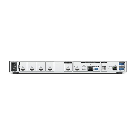
Page 15: Rear Panel Features And Connections
If the MGP 641 is to be connected to a computer or to a host controller for remote control, connect an RS-232 cable from the host to the 5-pole Remote RS-232 rear panel connector (see figure 2, ) or to the front panel USB mini-B Config port (see figure 8,... - Page 16 3-pole Over TP IR captive screw port (see figure 2, on the previous page). shows how to wire the connector. Figure 3 MGP 641 Tx, Rx, and G Pins IR Device Figure 3. Wiring the Over TP IR Connector MGP 641 Series • Installation...
- Page 17 NOTE: RS-232 communication can also be sent to the far end of the twisted pair connection, but it must be done through RS-232 insertion via Ethernet. A control signal applied to an MGP 641 LAN port can be routed to the RS-232 port of any connected twisted pair device (see...
-
Page 18: Installing The Lockit Hdmi Cable Lacing Brackets
• Ne serrez pas trop la vis de montage du connecteur HDMI. Le blindage auquel elle est attachée est très fin et peut facilement être dénudé. MGP 641 Series • Installation... -
Page 19: Twisted Pair Recommendations For Dtp, Xtp, And Hdbt Communication
A control signal applied to an MGP 641 LAN port can be routed to the RS-232 port of the connected twisted pair device. The RS-232 inputs and outputs inserted via Ethernet can support up to a 115 K baud rate. -
Page 20: Connecting For Ethernet To Rs-232 Insertion
67) to configure the port RS-232 protocol (baud rate, parity, data bits, and stop bits). Connect the TP cable from the MGP 641 DTP Out connector to the input of the DTP endpoint (receiver). Connect a serial cable from the DTP receiver to the device to be controlled. -
Page 21: Operation
Operation This section describes setup and operating procedures for the MGP 641 available from the front panel. The following topics are discussed: Front Panel Features • • Power-up and Default Cycle • Selecting a Window and Input Muting and Freezing a Window •... -
Page 22: Power-Up And Default Cycle
Adjust knobs — Turn the horizontal ( [ ) and vertical ( { ) Adjust knobs to scroll through submenu options and preset memory slots, and to adjust picture Power-up and Default Cycle When the MGP 641 first powers up, the LCD screen displays an initial sequence of three screens: Extron... -
Page 23: Selecting A Window And Input
30 seconds of inactivity. Selecting a Window and Input The MGP 641 has four windows in which to display sources. To select a window is to select its associated input, or logo if assigned... -
Page 24: Muting And Freezing A Window
A preset is a set of window (input) parameters that you create and save as a preset in MGP 641 memory. You can recall a saved preset and implement its settings at any time. A preset enables you to save time by applying a group of settings to the MGP 641 simultaneously. - Page 25 Press the Enter button to recall the selected preset Window Preset selected. The LCD screen shows a message indicating that the preset was recalled (see the image at right). #nnn Recalled Recalled presets apply to both outputs. MGP 641 Series • Operation...
-
Page 26: Input Presets
Factory Default Preset Configurations Input Presets The MGP 641 has 128 input preset slots that are global, containing all of the settings for an input when the MGP 641 is used with an upstream matrix switcher. Input presets allow a matrix switcher with multiple types of video inputs to be connected to the MGP 641 to expand the number of input video sources. -
Page 27: Picture Controls
This enables presets to be used to set aspect ratio or for other quick sizing shortcuts. Picture Controls WINDOW WINDOW The MGP 641 has four picture control buttons located on the /IMAGE /IMAGE front panel to the left of the Preset Recall/Save and Enter SIZE ZOOM buttons. -
Page 28: Picture Controls Summary
Follow: Horizontal and vertical image position When completed: for the input aspect ratio and size are set to maintain the native aspect Auto Image Win 1 setting. ratio for the input rate with respect to the window Complete! being affected. MGP 641 Series • Operation... -
Page 29: Menus, Configuration, And Adjustments
LCD Screen with Menu and Next Buttons Menu System Overview The MGP 641 menu system consists of a main menu with seven options (menus). Each of these seven menus has a set of submenus, which enable you to make desired adjustments (see the Main Menu Flow diagram in figure 12... - Page 30 PRESS NEXT 30 sec. Next Figure 12. Main Menu Flow NOTE: From any menu or submenu, the MGP 641 saves all adjustment settings and times out to the default screens after 30 seconds of inactivity. MGP 641 Series • Operation...
-
Page 31: Input Configuration Menu
When HDCP authorization is disabled, the window displaying an encrypted source does not display content that requires HDCP. Instead, the window displays either a black screen or a warning message generated by the source. MGP 641 Series • Operation... -
Page 32: Output Configuration Menu
Adjust ( { ) knob to select one of the refresh rates. The resolutions and refresh rates are listed in the Refresh Rates in Hz Table on page 25 MGP 641 Series • Operation... - Page 33 2560 x 1080 2560 x 1440 2560 x 1600 3840 x 2160 4096 x 2160** Custom 1 - 10 For new resolutions * Default ** Resolution not available as an EDID, only as an output rate option MGP 641 Series • Operation...
- Page 34 • 1A: HDMI Format — Rotate either Adjust knob to select the digital format of HDMI output 1A. If Auto (the default) is selected, the MGP 641 uses the EDID from the connected sink device to determine the output format.
-
Page 35: Window Configuration Menu
(priority 1), move <2> all the way to the left, following the letter F on the LCD screen. Repeat steps 1 and 2 as desired for each additional window whose priority you want to change. MGP 641 Series • Operation... - Page 36 • Mute Effect — Use this submenu to select a transition effect for the MGP 641 to use when muting and unmuting windows. To select a transition effect: From the Window Configuration screen, press Next three times to display the Mute Effect screen.
-
Page 37: Image/Logo Configuration Menu
This image replaces the active video in the window. NOTE: All image keying parameters configured via VCS as part of the logo preset are applied to the image when it is scaled in a window (see the VCS Help File to configure logos). MGP 641 Series • Operation... - Page 38 If a new logo was selected, one of the following screens appears: • {Window number}: Win Recalled • Logo nnn • Foregnd Recalled Logo nnn Backgnd Recalled • Logo nnn Press Next again to move to the next Image/Logo Configuration menu item. MGP 641 Series • Operation...
-
Page 39: Advanced Configuration Menu
HDMI Background — Displays the unscaled image from the live background input • as the background on the screen. When this option is selected, the MGP 641 changes the live background refresh rate (not the resolution) to match that of the output. - Page 40 Color Bars Grayscale Audio Test Figure 18. Test Patterns Available for the MGP 641 NOTES: By default all test patterns include a single pixel wide crop pattern line. • The Audio Test pattern displays a crop pattern and also outputs pink noise at •...
- Page 41 NOTE: The equivalent SIS command is E ZXXX } . This command does not affect the current password, including the initial factory-set serial number. For other reset methods, see Resetting on page 36 MGP 641 Series • Operation...
-
Page 42: Comm Settings Menu
Use the Comm Settings menu to view and edit the serial communication port configuration and the MGP 641 IP addresses. This menu consists of two levels: View Comm Settings and Edit Comm Settings (Edit Comm Settings is accessed through View Comm Settings). -
Page 43: Additional Functions
Additional Functions HDCP Authorization The HDCP Authorized function allows the MGP 641 HDMI inputs to be able to report as an HDCP authorized sink or a non-HDCP authorized sink (display) device to a source device. This is especially useful for sources that encrypt their output even if the source material does not require HDCP encryption, which would then prevent content from being displayed on non-HDCP compliant displays. -
Page 44: Locking The Front Panel (Executive Mode)
Locking the Front Panel (Executive Mode) To prevent access by unauthorized users or accidental changes to the MGP 641 settings, some of the front panel controls can be locked using executive mode (the rear panel RS-232, front panel Config, and the LAN ports remain unlocked). - Page 45 Activation Result Purpose • The factory-installed default firmware Use mode 1 to Hold in the Reset button while applying power to the MGP 641. version is restored for a single power remove a version cycle. of firmware if incompatibility •...
-
Page 46: Remote Configuration And Control
Configuration and Control The MGP 641 can be configured and controlled via Extron Simple Instruction Set (SIS) commands when connected to a host computer or other device (such as a control system). Attach the host device to the rear panel RS-232 connector or LAN connector, or to the front panel USB port. -
Page 47: Initial Power Up Messages
• n.nn Password Messages If the MGP 641 is protected by a password, the following password message prompts you for the password to access the MGP features. ] Password ] The prompt requires a password, followed by a carriage return. The prompt is repeated if the correct password is not entered. -
Page 48: Processor-Initiated Messages
— Maximum number of connections exceeded — Invalid parameter — Bad filename or file not found — Not valid for this configuration — Bad file type or size — Invalid command for signal type MGP 641 Series • Remote Configuration and Control... -
Page 49: Sis Overview
( } ). • = Space character E or W Escape < > key (hex Error code response from the unit if a command is entered incorrectly (linked to Error Responses on page 40). MGP 641 Series • Remote Configuration and Control... - Page 50 Picture adjustment — 0 to 127 NOTE: Front panel lockout does not include Default = 64 RS-232, USB, and Ethernet control. Response is three digits, padded with zeros. MGP 641 Series • Remote Configuration and Control...
- Page 51 Custom EDID/Output rate 7 Custom EDID/Output rate 8 Custom EDID/Output rate 9 Custom EDID/Output rate 10 *Default output resolution **Default EDID ***Not available as an EDID, only as an output rate option MGP 641 Series • Remote Configuration and Control...
- Page 52 = No active input, timer expired, output sync display the new signal as quickly as possible. disabled Also removes two frames of video delay from the video processing logic and may introduce video artifacts during the switch. MGP 641 Series • Remote Configuration and Control...
- Page 53 3 = Multi-Ch — Configures input EDID for Multi-Ch support. Passes all digital audio input signals to the HDMI outputs. If LPCM-2Ch audio is present it is also de-embedded to the 5-pole captive screw analog output. MGP 641 Series • Remote Configuration and Control...
- Page 54 Default name — A combination of the model name performance. and the last three character pairs of the unit MAC address. Example: MGP-641-00-02-3D) X15@ Connection security level 0 = Not logged in 1 = User 2 = Administrator MGP 641 Series • Remote Configuration and Control...
- Page 55 Example: 255.255.240.0 is represented as /20. the geographical area. The description is formatted as {UTC offset} : {location name}. X17! Network Time Protocol (NTP) setting 0 = Enabled 1 = Disabled 2 = Synced MGP 641 Series • Remote Configuration and Control...
-
Page 56: Command And Response Table For Mgp 641 Sis Commands
Command and Response Table for MGP 641 SIS Commands ASCII Response Command Additional Description (Host to Processor) (Processor to Host) Input Configuration Input Video Format View detected input format X! *\ X1*] View video format detected on input Verbose modes 2 and 3:... - Page 57 Saving a single space repopulates with the default name. 1 = Fill — Each input rate fills the entire window (default). = Aspect ratio setting 2 = Follow — Each input rate is displayed with its native aspect ratio. MGP 641 Series • Remote Configuration and Control...
- Page 58 = Mute video and sync (for output mute only). 0 = Disabled (default) = Image or display rotation 1 = 90 degrees clockwise (the LCD panel displays +90 degrees) 2 = 90 degrees counterclockwise (the LCD panel displays -90 degrees) MGP 641 Series • Remote Configuration and Control...
- Page 59 = Horizontal and vertical size (width and Minimum = 1/16 the size of the active output area. height) Maximum = 2x size of the active output area. Response is five digits, padded with zeros. MGP 641 Series • Remote Configuration and Control...
- Page 60 = Horizontal and vertical size (width and Minimum = 1/16 the size of the active output area. height) Maximum = 2x size of the active output area. Response is five digits, padded with zeros. MGP 641 Series • Remote Configuration and Control...
- Page 61 = Horizontal and vertical size (width and Minimum = 1/16 the size of the active output area. height) Maximum = 2x size of the active output area. Response is five digits, padded with zeros. MGP 641 Series • Remote Configuration and Control...
- Page 62 InfoFrames 0 = Disabled (default) = Input or display rotation 1 = 90 degrees clockwise (the LCD panel displays +90 degrees) 2 = 90 degrees counterclockwise (the LCD panel displays -90 degrees) MGP 641 Series • Remote Configuration and Control...
- Page 63 2 = No active input, timer expired, output sync disabled Window border style presets — 0 - 128 = Window border style 0 = No border Response is three digits, padded with zeros. MGP 641 Series • Remote Configuration and Control...
- Page 64 The first character must be a letter. • The last character cannot be a hyphen. • Not case-sensitive. 1 - 128 = Window preset number Response is three digits, padded with zeros. MGP 641 Series • Remote Configuration and Control...
- Page 65 The first character must be a letter. • The last character cannot be a hyphen. • Not case-sensitive. 1 - 128. Response is three digits, padded with zeros. = Input preset number MGP 641 Series • Remote Configuration and Control...
- Page 66 Passes all digital audio input signals to the HDMI outputs. Audio input format on page 45 3 = Multi-Ch — Configures input EDID for Multi-Ch support. Passes all for more information.) digital audio input signals to the HDMI outputs. MGP 641 Series • Remote Configuration and Control...
- Page 67 • The last character cannot be a hyphen. • Not case-sensitive. X2& 1 - 32. Response is three digits, padded with zeros. = Logo or image slot number 0 = No image MGP 641 Series • Remote Configuration and Control...
- Page 68 3 = Blue of RGB key 4 = Level key 0 - 255 = Logo effect level setting 0 = Disabled (default), 1 = Transparency, 2 = RGB key, = Logo key effect 3 = Level key MGP 641 Series • Remote Configuration and Control...
- Page 69 A negative (–) number shifts the clock or logo to the left. A positive (+) number shifts it to the right. 0 = Off or disabled (default), 1 = On or enabled = On or off status MGP 641 Series • Remote Configuration and Control...
- Page 70 3 = Seamless cut — Freeze last frame on loss or change of sync and seamlessly cut to new signal when it is locked. 4 = Low latency mode — Display the new signal as quickly as possible. MGP 641 Series • Remote Configuration and Control...
- Page 71 0 = Video or TMDS signal not detected = Video signal status 1 = Video or TMDS signal detected Response format: Input1*Input2*Input3*Input4*Background Input DTP (default), 1 XTP, 2 = HDBaseT = Twisted pair format MGP 641 Series • Remote Configuration and Control...
- Page 72 0 = IP config file (ip.cfg) = Configuration file type 2 = Unit-specific parameters file (box.cfg) NOTE: Configuration files are stored on directory/nortxe-backup, which is created on the unit when the configuration is saved. MGP 641 Series • Remote Configuration and Control...
- Page 73 This command is required after any changes are made to the IP address, subnet mask, DHCP, or gateway, unless the changes are made via a CISG command (see Set Multiple IP Parameters with a Single Command (CISG Commands) on page 70). MGP 641 Series • Remote Configuration and Control...
-
Page 74: Command And Response Table For Ip Sis Commands
The UTC equivalent for a particular time zone as well as a = Time zone description general description of the geographical area. The description is formatted as {UTC offset} : {location name}. MGP 641 Series • Remote Configuration and Control... - Page 75 Default: Empty string (enter a single space) X17! 0 = Enabled, 1 = Disabled, 2 = Sync now = Network Time Protocol (NTP) setting MGP 641 Series • Remote Configuration and Control...
- Page 76 2 = Verbose mode is off, tagged responses are sent for queries (tagged responses are enabled). 3 = Verbose mode is on (enabled) and tagged responses are enabled and sent for queries. MGP 641 Series • Remote Configuration and Control...
- Page 77 A combination of the model name and the last three character pairs of = Default unit name the unit MAC address. Example: MGP-641-00-02-3D) X15@ 0 = Not logged in, 1 = User, 2 = Administrator = Session security level MGP 641 Series • Remote Configuration and Control...
- Page 78 (min = 1 (10 seconds), max = 65000 (650,000 seconds), and default = 30 (300 seconds). If no data is received during the timeout period, the Ethernet connection is closed. Each step is 10 seconds. MGP 641 Series • Remote Configuration and Control...
- Page 79 *0 PMAP PmapB• *00000 port. View the SIS-over-SSH port View the current SIS-over-SSH PMAP {port number} mapping port. KEY: 0 = disabled, 1 = enabled Echo status Network interface card (NIC) number MGP 641 Series • Remote Configuration and Control...
- Page 80 If the admin password is cleared, the user password is cleared also. If there is a valid password, the response is **** . If there is no password, the response is NOTE: MGP 641 Series • Remote Configuration and Control...
-
Page 81: Videowall Configuration Software (Vcs) Program
Videowall Configuration Software (VCS) Program The Extron VCS program is a PC-based program for the MGP 641 that provides a convenient way to configure the processor. System configuration is broken down into logical tasks, including output and wall configuration, source setup, window preset design, and EDID Minder. - Page 82 By default, the installation places the program files at: C:\Program Files (x86)\Extron\Extron VCS. If there is not already an Extron folder in your Program Files x86 folder, the installation program creates it as well. MGP 641 Series • Remote Configuration and Control...
-
Page 83: Starting The Configuration Program
VCS New Project Screen Select the MGP radio button (see figure 25, NOTE: You cannot proceed without selecting a device type. Click the Create button ( ). A Passwords window opens. Figure 26. Passwords Window MGP 641 Series • Remote Configuration and Control... - Page 84 Click OK on the prompt to close it. Click Close on the Passwords window. VCS searches for MGP 641 devices connected to the network. The Connection screen displays a list of detected MGP 641 devices (see figure 27 ). Proceed to step 6 on the next page.
- Page 85 Network Adapter Screen Click OK to confirm your selection. the Network Adapter screen closes. On the Connection screen, locate your MGP 641 on the list and click the Add to System button at the left of the device name (see figure 29, ).
- Page 86 Communication Settings button at the bottom left of the screen to display the Communication Settings dialog box. For detailed instructions on using VCS to configure the videowall, see the VCS Help File. MGP 641 Series • Remote Configuration and Control...
-
Page 87: Html Configuration And Control
HTML Configuration and Control The MGP 641 features an internal web server, displayed as a web page. This page allows you to monitor and adjust certain settings of the MGP via a LAN connection. Use a web browser to view the pages on a PC connected to the MGP LAN port. -
Page 88: Disabling Compatibility Mode
Tools menu of the browser. The Compatibility View Settings dialog box opens. Be sure that the Display all websites in Compatibility View checkbox is clear, and that the IP address of the MGP 641 is not in the list of websites that have been added to Compatibility View. -
Page 89: Web Page Components
Network Settings Panel Inputs Panel Inputs Panel Outputs Panel Outputs Panel RS-232 Panel RS-232 Panel Roles and Permissions Panel Roles and Permissions Panel Firmware Panel Firmware Panel Figure 33. Internal Web Page MGP 641 Series • HTML Configuration and Control... -
Page 90: Device Info Panel
To view the status and type of all inputs, click the 3 More link in the lower-left corner of the Inputs panel to view the Inputs dialog box (see figure 35 for an example). on the next page MGP 641 Series • HTML Configuration and Control... -
Page 91: Roles And Permissions Panel
In the Roles and Permissions panel, click Edit. The Role and Permission Settings dialog box opens In the Admin panel, click the Change Admin Password link and enter the new administrator password in the field below (see figure 36, on the next page). MGP 641 Series • HTML Configuration and Control... -
Page 92: Device Status Panel
Syncing the date and time on the MGP 641 to the PC To set the MGP 641 date and time to match that of your computer: Click Sync to PC at the bottom of the Device Status panel. When the sync is completed, the message shown in figure 37 appears in the upper-right corner of the screen. - Page 93 Time Zone — In the Timezone field, select the desired time zone from the drop-down menu ( • NTP Server — If appropriate, enter the name of the network server from which the MGP obtains the date and time ( MGP 641 Series • HTML Configuration and Control...
-
Page 94: Outputs Panel
The Firmware panel ( ) displays the current firmware version and the date it was last updated. You can also update the firmware on your MGP 641 from this panel (firmware files can be downloaded from www.extron.com, see Downloading the Firmware ). -
Page 95: Network Settings Panel
In the Network Settings panel (see figure 33, on page 81), you can set the IP address, subnet mask, and gateway address for your MGP 641, and turn DHCP on and off. You can also view the MAC address of the unit. To set the IP addresses: Click Edit in the lower-left corner of the Network Settings panel. -
Page 96: Rs-232 Panel
IP address. RS-232 Panel The view-only RS-232 panel (see figure 33, on page 81) displays the RS-232 protocol for the MGP 641 serial port. The defaults are: Baud rate — 9600 • Parity Bit — N (none) •... -
Page 97: Reference Information
Please contact Extron if you have any questions about the guidelines outlined in this section or if you have a question about cleaning a specific Extron product. MGP 641 Series • Reference Information... -
Page 98: Mounting The Mgp 641
IP connection without opening the unit. Determining the Firmware Version There are three ways to check which version of firmware the MGP 641 is using: view the front panel LCD window during power-on, the Firmware panel of the MGP 641 embedded web page, or the Device Settings tab in VCS. - Page 99 Using the LCD display at Power-on Watch the LCD window as you connect the MGP 641 to a power source. The third introductory screen (see figure 43, ) contains device part number and the firmware version and build. Extron Extron Power...
-
Page 100: Downloading The Firmware
Downloading the Firmware To obtain the latest version of MGP 641 firmware file and install it on your computer: Figure 45. Downloading Firmware from the Extron Website On www.extron.com, click the Download tab (see figure 45, ) in the Downloads column. - Page 101 The file can be downloaded from the same page as the firmware. Scroll to locate the MGP 641 on the page ( Click the Download link ( ) at the right edge of the MGP 641 row.
-
Page 102: Uploading The Firmware To The Mgp 641
MGP to stop functioning. The computer and the MGP 641 must both be connected to an Ethernet network in order to update the main firmware. It is recommended that you always perform firmware upgrades via an IP connection. -
Page 103: Subnet Mask
It is important that you set the correct value for the subnet mask. The basic values depend on the class of IP address being used. Class Name Subnet Mask Class A 255.0.0.0 Class B 255.255.0.0 Class C 255.255.255.0 Subnetting, a Primer for more information. on page 97 MGP 641 Series • Reference Information... -
Page 104: Pinging For The Ip Address
Pinging for the IP Address To access the MGP 641 via the Ethernet port, you need the processor IP address. If the address has been changed to an address comprised of words and characters, the actual numeric IP address can be determined using the Ping utility. If the address has not been changed, the factory-specified default is 192.168.254.254. -
Page 105: Subnetting, A Primer
MGP 641, you must understand the concepts of a gateway, local and remote devices, IP addresses and octets, and subnet masks and octets. Gateways The MGP 641 can communicate with devices on different subnets via a gateway, which is a computer that provides a link between different subnets. Local and remote devices The local and remote devices are defined from the point of view of the function being described. - Page 106 190.190.2.25 192.190.2.25 Match?: = . = .n.n — Match z . z .n.n — No match . z .n.n — No match (Same subnet) (Different subnet) (Different subnet) Figure 50. Comparing the IP Addresses MGP 641 Series • Reference Information...
- Page 107 Extron Warranty Extron warrants this product against defects in materials and workmanship for a period of three years from the date of purchase. In the event of malfunction during the warranty period attributable directly to faulty workmanship and/ or materials, Extron will, at its option, repair or replace said products or components, to whatever extent it shall deem necessary to restore said product to proper operating condition, provided that it is returned within the warranty period, with proof of purchase and description of malfunction to: USA, Canada, South America,...
Need help?
Do you have a question about the MGP 641 and is the answer not in the manual?
Questions and answers