Table of Contents
Advertisement
Quick Links
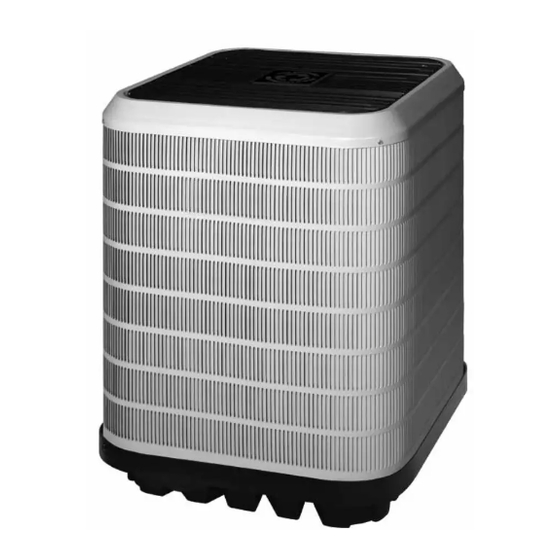
Split SyStem air conditioner
inStallation inStructionS
*S4Be / *Sa4Be - 018, 024, 030, 036, 042, 048, & 060 (1.5, 2, 2.5, 3, 3.5, 4, & 5 ton) Series
important
attention inStallerS:
it is your responsibility to know this product
better than your customer. this includes
being able to install the product according
to strict safety guidelines and instructing the
customer on how to operate and maintain the
equipment for the life of the product. Safety
should always be the deciding factor when
installing this product and using common
sense plays an important role as well. pay
attention to all safety warnings and any other
special notes highlighted in the manual.
improper installation of the furnace or failure
to follow safety warnings could result in
serious injury, death, or property damage.
these instructions are primarily intended to
assist qualified individuals experienced in the
proper installation of this appliance. Some
local codes require licensed installation/
service personnel for this type of equipment.
please read all instructions carefully before
starting the installation. return these
instructions to the customer's package for
future reference.
do not deStroy. pleaSe read carefully &
Keep in a Safe place for future reference.
14 Seer, Single phaSe modelS
important Safety information ................. 2
air conditioner inStallation .................... 3
General Information .............................................. 3
Before You Install this Unit ..................................... 3
Locating the Air conditioner................................... 3
Packaging Removal .............................................. 3
Ground Level ......................................................... 3
Roof Mount............................................................ 3
Indoor & Outdoor Unit ........................................... 4
electrical Wiring ........................................... 4
Pre - Electrical Checklist ....................................... 4
Line Voltage ........................................................... 4
Grounding ............................................................. 5
Diagnostics Module ..................... 5
24VAC Power Wiring ........................................... 5
Thermostat Demand Wiring ................................ 5
Interpreting the Diagnostic LED's ....................... 6
LED Description .................................................. 6
Thermostat Low / Voltage Connections ................. 6
Startup & adjuStmentS ............................... 6
Pre - Start Checklist .............................................. 6
Start-up Procedures .............................................. 6
Air Circulation - Indoor Blower .............................. 6
System Cooling ..................................................... 6
System Heating ..................................................... 7
air conditioner maintenance .................... 7
refrigerant charging ................................. 7
Outdoor Temperatures Above 55° F ...................... 7
component functionS .................................. 9
electrical diagramS & taBleS .................. 9
Figure 4. W.D., (without Comfort Alert) ............... 9
Figure 5. W.D., (with Comfort Alert) .................. 10
Table 3. Comfort Alert LED Diagnostics ............ 11
Table 4. Module Wiring Troubleshooting ............ 12
inStall. / performance checKliSt ......... 16
replacement partS ...................................... 16
Advertisement
Table of Contents

Related Manuals for Nortek SA4BE Series


Summary of Contents for Nortek SA4BE Series
-
Page 1: Table Of Contents
Split SyStem air conditioner 14 Seer, Single phaSe modelS inStallation inStructionS *S4Be / *Sa4Be - 018, 024, 030, 036, 042, 048, & 060 (1.5, 2, 2.5, 3, 3.5, 4, & 5 ton) Series important Safety information ....2 important air conditioner inStallation ....3 General Information .......... -
Page 2: Important Safety Information
important Safety information INSTALLER: Please read all instructions before caution: servicing this equipment. Pay attention to all safety warnings and any other special notes highlighted this unit uses refrigerant r-410a. do not use in the manual. Safety markings are used frequently any other refrigerant in this unit. -
Page 3: Air Conditioner Installation
air conditioner inStallation packaging removal note: To prevent damage to the tubing connections, general information carefully remove the carton and user’s manual from the The S4BE series air conditioner is designed only for equipment. Discard the shipping carton. outdoor rooftop or ground level installations. This unit has been tested for capacity and efficiency in accordance ground level with AHRI Standards and will provide many years of safe... -
Page 4: Connecting Refrigerant Tubing Between The Indoor & Outdoor Unit
connecting refrigerant tubing Between the indoor electrical Wiring & outdoor unit Warning: caution: to avoid risk of electrical shock, personal When servicing, cover or seal openings to injury, or death, disconnect all electrical power minimize the exposure of the refrigerant system to the unit before performing any maintenance to air to prevent accumulation of moisture and or service. -
Page 5: Grounding
• Provide power supply for the unit in accordance with the copper Wire SiZe — aWg unit wiring diagram, and the unit rating plate. Connect (1% Voltage drop) the line-voltage leads to the terminals on the contactor inside the control compartment. Supply Wire length-feet Supply circuit •... -
Page 6: Interpreting The Diagnostic Led's
Interpreting the Diagnostic LED’s recommended t-Stat Wire When an abnormal system condition occurs, the Comfort unit to t-Stat (length in ft) thermostat Alert module displays the appropriate ALERT and/or Wire gauge 2-Wire 5-Wire TRIP LED will flash a number of times consecutively, (heating) (heating/cooling) pause and then repeat the process. -
Page 7: System Heating
thermostat. note: The blower should also stop unless refrigerant charging fan mode is set to the ON position. Warning: System Heating (optional) 1. Set the thermostat's system mode to HEAT and the S4Be Split System air conditioners are shipped temperature mode above room temperature. charged with r410a refrigerant and ready 2. -
Page 8: Application Notes For Using The Charging Chart
application notes for using the charging chart make sure the unit is in a stable operating mode. As shown in Figure 3 (page 8), the ideal system sub- • this equipment’s cooling system contains cooling can vary over the range of operation. Reference refrigerant under high pressure. -
Page 9: Component Functions
component functionS comfort alert diagnostics (Select models only) The Comfort Alert diagnostics module troubleshoots heat pump and air conditioning system failures and accurately detects the cause of electrical and system related failures without any sensors. A flashing LED indicator communicates the ALERT code to quickly direct the technician to the root cause of a problem. - Page 10 Yellow Black Yellow figure 5. Wiring diagram for S4Be Single phase models (with comfort alert)
- Page 11 Status led Status led description Status led troubleshooting information POWER Module has power Supply voltage is present at module terminals (Green LED) • Compressor protector is open • Check for high head pressure • Check compressor supply voltage Thermostat demand signal Y •...
- Page 12 Status led Status led description Status led troubleshooting information • Run capacitor has failed • Open circuit in compressor start wiring or connections ALERT Open Start Circuit Flash Code 6 — Check wiring and connectors between supply and the compressor S terminal Current only in run circuit •...
-
Page 16: Install. / Performance Checklist
inStallation / performance checK liSt electrical SyStem: inStallation addreSS: Electrical connections tight? Line voltage polarity correct? CITY ________________________ STATE ________________ Rated Voltage: ___________________________________ VOLTS UNIT MODEL # ________________________________________ UNIT SERIAL # _______________________________________ L1-L2 Volts: _____________________________________ VOLTS inStaller name: L1-L3 Volts: _____________________________________ VOLTS CITY _______________________ STATE ________________ L2-L3 Volts: _____________________________________ VOLTS...
Need help?
Do you have a question about the SA4BE Series and is the answer not in the manual?
Questions and answers