Table of Contents
Advertisement
Quick Links
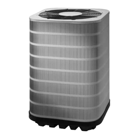
Split SyStem air conditioner
inStallation inStructionS
S4Be - 018, 024, 030, 036, 042, 048, & 060 (1.5, 2, 2.5, 3, 3.5, 4, & 5 ton) Series
important SaFety inFormation ................. 2
air conditioner inStallation .................... 3
General Information .............................................. 3
Before You Install this Unit ..................................... 3
Locating the Air conditioner................................... 3
Packaging Removal .............................................. 3
Ground Level ......................................................... 3
Roof Mount............................................................ 3
Indoor & Outdoor Unit ........................................... 4
electrical Wiring ........................................... 4
Pre - Electrical Checklist ....................................... 4
Line Voltage ........................................................... 4
Diagnostics Module ..................... 5
24VAC Power Wiring ........................................... 5
Thermostat Demand Wiring ................................ 5
Interpreting the Diagnostic LED's ....................... 5
LED Description .................................................. 6
Grounding ............................................................. 6
Thermostat Low / Voltage Connections ................. 6
Startup & adjuStmentS ............................... 6
Pre - Start Checklist .............................................. 6
Start-up Procedures .............................................. 6
Air Circulation - Indoor Blower .............................. 6
it is your responsibility to know this product better than your customer. this includes being
able to install the product according to strict safety guidelines and instructing the customer on
how to operate and maintain the equipment for the life of the product. Safety should always be
the deciding factor when installing this product and using common sense plays an important
role as well. pay attention to all safety warnings and any other special notes highlighted in the
manual. improper installation of the furnace or failure to follow safety warnings could result in
serious injury, death, or property damage.
these instructions are primarily intended to assist qualified individuals experienced in the
proper installation of this appliance. Some local codes require licensed installation/service
personnel for this type of equipment. please read all instructions carefully before starting the
installation. return these instructions to the customer's package for future reference.
do not deStroy. pleaSe read careFully & Keep in a SaFe place For Future reFerence.
System Cooling ..................................................... 6
System Heating ..................................................... 7
Refrigerant Charging ............................................. 7
Outdoor Temperatures Above 55° F ...................... 6
air conditioner maintenance .................... 6
component FunctionS .................................. 8
charging chartS ............................................ 8
Figure 3. Charging Chart for 1.5 Ton Units .......... 9
Figure 4. Charging Chart for 2 Ton Units ............. 9
Figure 5. Charging Chart for 2.5 Ton Units ........ 10
Figure 6. Charging Chart for 3 Ton Units ........... 10
Figure 7. Charging Chart for 3.5 Ton Units ........ 11
Figure 8. Charging Chart for 4 Ton Units ........... 11
Figure 9. Charging Chart for 5 Ton Units ........... 12
comFort alert trouBleShooting.......... 12
Table 3. Module Wiring Troubleshooting ............ 12
Table 4. Comfort Alert LED Diagnostics ............ 13
electrical diagramS & taBleS ................ 14
Figure 10. W.D., (with Comfort Alert) ................ 14
Figure 11. W.D., (without Comfort Alert) ........... 15
inStall. / perFormance checKliSt ......... 16
replacement partS ...................................... 16
important
attention inStallerS:
14 Seer, Single phaSe modelS
Advertisement
Table of Contents

Related Manuals for Nortek S4Be Series


Summary of Contents for Nortek S4Be Series
-
Page 1: Table Of Contents
Split SyStem air conditioner 14 Seer, Single phaSe modelS inStallation inStructionS S4Be - 018, 024, 030, 036, 042, 048, & 060 (1.5, 2, 2.5, 3, 3.5, 4, & 5 ton) Series important SaFety inFormation ....2 System Cooling ............. 6 System Heating ............. -
Page 2: Important Safety Information
important SaFety inFormation INSTALLER: Please read all instructions before caution: servicing this equipment. Pay attention to all safety warnings and any other special notes highlighted this unit uses refrigerant r-410a. do not use in the manual. Safety markings are used frequently any other refrigerant in this unit. -
Page 3: Air Conditioner Installation
To prevent damage to the tubing connections, general information carefully remove the carton and user’s manual from the The S4BE series air conditioner is designed only for equipment. Discard the shipping carton. outdoor rooftop or ground level installations. This unit has... -
Page 4: Connecting Refrigerant Tubing Between The Indoor & Outdoor Unit
connecting refrigerant tubing Between the indoor electrical Wiring & outdoor unit Warning: caution: to avoid risk of electrical shock, personal When servicing, cover or seal openings to injury, or death, disconnect all electrical power minimize the exposure of the refrigerant system to the unit before performing any maintenance to air to prevent accumulation of moisture and or service. -
Page 5: Comfort Alert Tm Diagnostics Module
See the unit rating plate for minimum circuit ampacity copper Wire SiZe — aWg and maximum overcurrent protection limits. (1% Voltage drop) • Provide power supply for the unit in accordance with the unit wiring diagram, and the unit rating plate. Connect Supply Wire length-Feet Supply circuit the line-voltage leads to the terminals on the contactor... -
Page 6: Led Description
LED Description recommended t-Stat Wire • POWER LED (Green): indicates voltage is present at unit to t-Stat (length in Ft) thermostat the power connection of the module. Wire gauge • ALERT LED (Yellow): communicates an abnormal 2-Wire 5-Wire (heating) (heating/cooling) system condition through a unique flash code. -
Page 7: System Heating
thermostat. note: The blower should also stop unless Remove refrigerant and repeat Steps 1 through 3 fan mode is set to the ON position. until the system is correctly charged. • If the pressure measured in Step 1 is less than the System Heating (optional) required liquid refrigerant pressure determined in 1. -
Page 8: Component Functions
component FunctionS close again once the liquid pressure decreases to 460 psig. Please note that the switch interrupts the thermostat comfort alert diagnostics (Select models only) inputs to the unit. Thus, when the switch opens and then The Comfort Alert diagnostics module troubleshoots closes, there may be a 5 minute short cycling delay before heat pump and air conditioning system failures and the outdoor unit will energize. - Page 9 S4BE-018K Charging Chart - Cooling Remove refrigerant when above curve Add refrigerant when below curve Liquid Temperature (F) Figure 3. charging chart for S4Be-018 Series (1.5 ton units) - tXV matches S4BE-024K Charging Chart - Cooling Remove refrigerant when above curve Add refrigerant when below curve Liquid Temperature (F) Figure 4.
- Page 10 S4BE-030K Charging Chart - Cooling Remove refrigerant when above curve Add refrigerant when below curve Liquid Temperature (F) Figure 5. charging chart for S4Be-030 Series (2.5 ton units) - tXV matches S4BE-036K Charging Chart - Cooling Remove refrigerant when above curve Add refrigerant when below curve Liquid Temperature (F) Figure 6.
- Page 11 S4BE-042K Charging Chart - Cooling Remove refrigerant when above curve Add refrigerant when below curve Liquid Temperature (F) Figure 7. charging chart for S4Be-042 Series (3.5 ton units) - tXV matches S4BE-048K Charging Chart - Cooling Remove refrigerant when above curve Add refrigerant when below curve Liquid Temperature (F) Figure 8.
-
Page 12: Comfort Alert Troubleshooting
S4BE-060K Charging Chart - Cooling Remove refrigerant when above curve Add refrigerant when below curve Liquid Temperature (F) Figure 9. charging chart for S4Be-060 Series (5 ton units) - tXV matches comFort alert trouBleShooting miswired module indication recommended troubleshooting action •... - Page 13 Status led Status led description Status led troubleshooting information POWER Module has power Supply voltage is present at module terminals (Green LED) • Compressor protector is open • Check for high head pressure • Check compressor supply voltage Thermostat demand signal Y •...
-
Page 14: Electrical Diagrams & Tables
comFort alert trouBleShooting - continued Status led Status led description Status led troubleshooting information • Run capacitor has failed • Open circuit in compressor start wiring or connections ALERT Open Start Circuit Flash Code 6 — Check wiring and connectors between supply and the compressor S terminal Current only in run circuit •... - Page 15 Yellow Black Yellow Figure 11. Wiring diagram for S4Be Single phase models (with comfort alert)
-
Page 16: Install. / Performance Checklist
inStallation / perFormance checK liSt electrical SyStem: inStallation addreSS: Electrical connections tight? Line voltage polarity correct? CITY ________________________ STATE ________________ Rated Voltage: ___________________________________ VOLTS UNIT MODEL # ________________________________________ UNIT SERIAL # _______________________________________ L1-L2 Volts: _____________________________________ VOLTS inStaller name: L1-L3 Volts: _____________________________________ VOLTS CITY _______________________ STATE ________________ L2-L3 Volts: _____________________________________ VOLTS...
Need help?
Do you have a question about the S4Be Series and is the answer not in the manual?
Questions and answers