CAMPAGNOLO Ergopower 12s Technical Manual
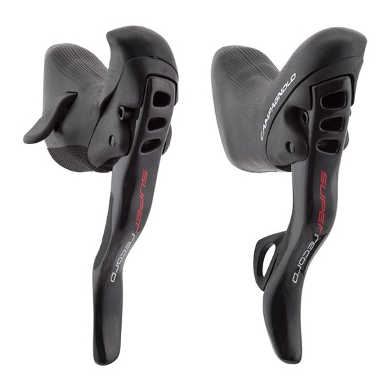
Control lever
Hide thumbs
Also See for Ergopower 12s:
- User manual (148 pages) ,
- Technical manual (12 pages) ,
- Installation instructions manual (12 pages)
Advertisement
Quick Links
Advertisement

Related Manuals for CAMPAGNOLO Ergopower 12s


Summary of Contents for CAMPAGNOLO Ergopower 12s
- Page 1 ERGOPOWER CONTROL LEVERS 12s / 13s C A M PA G N O L O. CO M...
- Page 2 WARNING! Always wear protective gloves and glasses while working on the bicycle. ER GOPOWE R CO N T RO L L EV ER S - R ev. 0 0 / 0 7 - 2 0 2 2 CA M PA G NO L O C O M PO NE NT S - T E C H NIC A L M A NUA L...
-
Page 3: Technical Specifications
R EA R D ER AILLEU R POWER-SHIFT POWER-SHIFT Ø 4.1 mm Ø 4.1 mm (EKAR 13s) (EKAR 13s) Campagnolo maximum smoothness Campagnolo maximum smoothness Ø 4.1 mm Ø 4.1 mm Campagnolo maximum smoothness Campagnolo maximum smoothness 2 - COM PATIB I L I T Y 2.1 - M E C H A NI C A L GRO UP SE T... - Page 4 2.2 - EP S G R O UP S E T ERGOPOW E R ERGOPOW E R F R O NT D ER A I L LEU R F R O NT D ER A I L LEU R ULTRA-SHIFT 12s EPS ULTRA-SHIFT 12s EPS CONTROL L E VE RS CONTROL L E VE RS...
- Page 5 3 - I NTE RFACE W IT H H AND LEBAR 3 .1 - IN T ER FA C E W I T H HA N DL E BAR F O R E R G O P OWE R M E CH ANI CA L / E P S CO N TR O L S WARNING! Combinations other than those provided for in the above table could cause the drivetrain to malfunction and potentially be the cause...
- Page 6 α CAUTION The cable routing illustrated in Figure 3 seriously compromises the drivetrain’s gear shift and derailing performance. DO NOT USE HANDLEBAR BENDS WITH THIS KIND OF ROUTING. • Make sure that angle α is sufficiently wide to ensure that the housing is mounted correctly and the cable runs through it easily (Fig. 4). ER GOPOWE R CO N T RO L L EV ER S - R ev.
- Page 7 4 - ASS EM BLY • Fold back the rear of the hood (A - Fig. 1) to expose the securing screw (B - Fig. 1). • Loosen the bolt (B - Fig. 1) positioned in the top of the body sufficiently to fit the clamp (C - Fig.
- Page 8 • Depending on your frame, it may be necessary to cut the rear brake housing and install a housings end (not supplied in your Ergopower™ control levers package). and install a casing lead end (not supplied in your Ergopower™ control levers package).
- Page 9 4 . 1 . 1 - REAR DE RAI L L EU R C AB LE AN D HO U SI NG S • Lift up the hood and push the end of the 680 mm long, 4.1 mm diameter housing into the hole provided (Fig. 11). Slightly bend the cable (for the first 5 –...
- Page 10 • Please make sure that the cable is flowing freely within the sheath. Verify in particular that the sheath head entries are rectilinear (Fig. 17), to avoid hindrances to the gear- shifting system. • If the sheath is too short, the shift function will be affected (Fig.17).
-
Page 11: Adju S T In G T He Ca Bl E T E N S Io N
(C - Fig. 21) on the frame. • If the frame is the type with internal cable routing, the Campagnolo cable tension adjuster for the front derailleur included in the package of the Ergopower commands must also be installed. Fit the tension adjuster with the knurled part at the bottom. - Page 12 4 .2 - B RAKE CABL E AN D S HE AT H (in t he case of a h yd ra u li c b ra ke , r e f er t o t h e Te chn i cal Ma nu a l: Di s c b ra ke h y d raul i c s yst e m ) 4 .
-
Page 13: Maintenance
• Never spray your bicycle with water under pressure. Pressurized water, even from the nozzle of a small garden hose, can pass seals and enter into your Campagnolo® components, damaging them beyond repair. Wash your bicycle and Campagnolo® components by wiping them down with water and neutral soap.
Need help?
Do you have a question about the Ergopower 12s and is the answer not in the manual?
Questions and answers