Omron CK3E Series Hardware User Manual
Programmable multi-axis controller
Hide thumbs
Also See for CK3E Series:
- Startup manual (62 pages) ,
- Connection manual (42 pages) ,
- Connection manual (42 pages)

Subscribe to Our Youtube Channel
Related Manuals for Omron CK3E Series


Summary of Contents for Omron CK3E Series
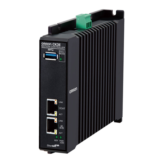
- Page 1 CK3E-series Programmable Multi-Axis Controller Hardware User’s Manual CK3E-110 Programmable Multi-Axis Controller I610-E1-04...
- Page 2 Moreover, because OMRON is constantly striving to improve its high-quality products, the information contained in this manual is subject to change without notice. 3. Every precaution has been taken in the preparation of this manual. Nevertheless, OMRON assumes no responsi- bility for errors or omissions.
-
Page 3: Intended Audience
Introduction Introduction Thank you for purchasing the CK3E-series Programmable Multi-Axis Controller (hereinafter, it may be abbreviated as “Motion Controller”). This manual contains information that is necessary to use the CK3E-series Programmable Multi-Axis Controller. Please read this manual and make sure you understand the functionality and performance of the product before you attempt to use it in a control system. -
Page 4: Manual Structure
Manual Structure Manual Structure Page Structure The following page structure is used in this manual. Level 1 heading 4 Installation and Wiring Level 2 heading Level 3 heading Mounting Units Level 2 heading Gives the current Level 3 heading headings. 4-3-1 Connecting Controller Components The Units that make up an NJ-series Controller can be connected simply by pressing the Units together... -
Page 5: Special Information
Manual Structure Special Information Special information in this manual is classified as follows: Precautions for Safe Use Precautions on what to do and what not to do to ensure safe usage of the product. Precautions for Correct Use Precautions on what to do and what not to do to ensure correct operation and performance. Additional Information Additional information to read as required. - Page 6 Manual Structure CK3E-series Programmable Multi-Axis Controller User’s Manual Hardware (I610)
-
Page 7: Sections In This Manual
Sections in this Manual Sections in this Manual Features and System Configuration Specifications Part Names and Functions Mounting and Wiring Troubleshooting Inspection and Maintenance Appendices Index CK3E-series Programmable Multi-Axis Controller User’s Manual Hardware (I610) -
Page 8: Table Of Contents
CONTENTS CONTENTS Introduction ......................1 Intended Audience............................1 Applicable Products ............................1 Manual Structure...................... 2 Page Structure..............................2 Special Information ............................3 Sections in this Manual ................... 5 Terms and Conditions Agreement................9 Warranty, Limitations of Liability ........................9 Application Considerations ..........................10 Disclaimers ..............................10 Statement of Security Responsibilities for Assumed Use Cases and Against Threats ......... 11 Safety Precautions.................... - Page 9 CONTENTS 2-2-1 USB Memory Device ........................2-5 2-2-2 Power Supply ..........................2-5 Section 3 Part Names and Functions Part Names and Functions....................3-2 Operation Indicators......................3-3 ID Information Indication Label ....................3-5 Section 4 Mounting and Wiring Processing at Power ON and Power OFF................4-2 4-1-1 Power ON Operation ........................4-2 4-1-2 Power OFF Operation .........................4-2...
- Page 10 CONTENTS Section 6 Maintenance and inspection Cleaning and Maintenance....................6-2 6-1-1 Cleaning ............................6-2 6-1-2 Periodic Inspections ........................6-2 Maintenance Procedures ......................6-4 6-2-1 Unit Replacement Precautions....................6-4 6-2-2 Backup ............................6-4 6-2-3 Unit Replacement........................6-4 Appendices Dimensions..........................A-2 Restrictions on Using the NX-series EtherCAT Coupler Unit........... A-4 Supported CIP Objects......................
-
Page 11: Terms And Conditions Agreement
Omron’s exclusive warranty is that the Products will be free from defects in materials and work- manship for a period of twelve months from the date of sale by Omron (or such other period ex- pressed in writing by Omron). Omron disclaims all other warranties, express or implied. -
Page 12: Application Considerations
WAY CONNECTED WITH THE PRODUCTS, WHETHER SUCH CLAIM IS BASED IN CONTRACT, WARRANTY, NEGLIGENCE OR STRICT LIABILITY. Further, in no event shall liability of Omron Companies exceed the individual price of the Product on which liability is asserted. Application Considerations... -
Page 13: Statement Of Security Responsibilities For Assumed Use Cases And Against Threats
Product. Errors and Omissions Information presented by Omron Companies has been checked and is believed to be accurate; how- ever, no responsibility is assumed for clerical, typographical or proofreading errors or omissions. Statement of Security Responsibilities for Assumed Use Cases and... -
Page 14: Safety Precautions
Safety Precautions Safety Precautions Definition of Precautionary Information The following notation is used in this manual to provide precautions required to ensure safe usage of the CK3E-series Programmable Multi-Axis Controller. The safety precautions that are provided are extremely important to help ensure safety. Always read and heed the information provided in all safety precautions. -
Page 15: Warning
Safety Precautions WARNING WARNING During Power Supply Do not attempt to take any Unit apart. In particular, high-voltage parts are present in the Power Supply Unit while power is supplied or immediately after power is turned OFF. Touching any of these parts may result in electric shock. -
Page 16: Cautions
Safety Precautions Downloading Always confirm safety at the destination before you transfer a user program, configura- tion data, or setup data from the Power PMAC IDE. The devices or machines may perform unexpected operation regardless of the operat- ing mode of the Controller. After you transfer the user program, the Controller is restarted and communications with the EtherCAT slaves are cut off. - Page 17 Safety Precautions Test Run When you perform a test run, take fail-safe measures and run the motor at a sufficient- ly low speed to ensure safety. Downloading Before you download a project written in C language, execute the re-initialization com- mand ($$$***).
-
Page 18: Precautions For Safe Use
Precautions for Safe Use Precautions for Safe Use Transporting • Do not drop any Unit or subject it to abnormal vibration or shock. Doing so may result in Unit mal- function or burning. Mounting • Be sure that the connectors and other items with locking devices are correctly locked into place be- fore use. - Page 19 Precautions for Safe Use Power Supply Design • In the system, only use a power supply within the rated supply capacity range specified in this man- ual. Turning ON the Power Supply • It takes approximately several tens of seconds to enter RUN mode after the power supply is turned ON.
- Page 20 Precautions for Safe Use EtherCAT Communications • Make sure that the communications distance, number of nodes connected, and method of connec- tion for EtherCAT are within specifications. Do not connect EtherCAT communications to EtherNet/IP, a standard in-house LAN, or other net- works.
- Page 21 Precautions for Safe Use c) Turn the power OFF and ON of the third-party slave, and check that other slaves are not in any errors. EtherNet/IP Communications • Unexpected operation may result if inappropriate data link tables are set. Even if appropriate data link tables have been set, confirm that the controlled system will not be adversely affected before you transfer the data link tables.
- Page 22 Precautions for Safe Use • Do not use corrosive chemicals to clean the Controller. Doing so may result in a failure or malfunc- tion of the Controller. • Dispose of the product according to local ordinances as they apply. CK3E-series Programmable Multi-Axis Controller User’s Manual Hardware (I610)
-
Page 23: Precautions For Correct Use
Precautions for Correct Use Precautions for Correct Use Storage and Installation • Follow the instructions in this manual to correctly perform installation. • Do not operate or store the Controller in the following locations. Doing so may result in burning, in operation stopping, or in malfunction. - Page 24 Precautions for Correct Use EtherCAT Communications • Set the Servo Drives to stop operation if an error occurs in EtherCAT communications between the Controller and a Servo Drive. • Always use the specified EtherCAT slave cables. If you use any other cable, the EtherCAT master or the EtherCAT slaves may detect an error and one of the following may occur.
-
Page 25: Regulations And Standards
Concepts EMC Directives OMRON devices that comply with EU Directives also conform to the related EMC standards so that they can be more easily built into other devices or the overall machine. The actual products have been checked for conformity to EMC standards.*1 Whether the products conform to the standards in the system used by the customer, however, must be checked by the customer. -
Page 26: Software Licenses And Copyrights
Regulations and Standards Software Licenses and Copyrights This product incorporates certain third party software. The license and copyright information associat- ed with this software is available at http://www.fa.omron.co.jp/nj_info_e/. CK3E-series Programmable Multi-Axis Controller User’s Manual Hardware (I610) -
Page 27: Related Manuals
Related Manuals Related Manuals The following manuals are related. Use these manuals for reference. Contact your OMRON represen- tative for information on how to procure these manuals. Manual name Cat. No. Application Description CK3E-series Programmable I610 Learning the basic An introduction to the entire CK3E-series system is... -
Page 28: Terminology
Terminology Terminology Term Description PMAC The acronym for Programmable Multi-Axis Controller. Motion con- Motion control can achieve intended operation by providing a target value to the axis to be controlled, or by trol controlling state transitions. Axis A functional unit within the Motion Control Function Module. An axis is assigned to the drive mechanism in an external Servo Drive, etc. -
Page 29: Revision History
Revision History Revision History A manual revision code appears as a suffix to the catalog number on the front and back covers of the manual. I610-E1-04 Revision code Revision Date Revised content code August 2016 Original production December 2018 Added to "Terms and Conditions Agreement". •... - Page 30 Revision History CK3E-series Programmable Multi-Axis Controller User’s Manual Hardware (I610)
-
Page 31: Features And System Configuration
Features and System Configura- tion This section describes the features and system configuration of the CK3E-series Pro- grammable Multi-Axis Controller. Features ......................1-2 Introduction to the System Configurations ..........1-3 Support Software ................... 1-5 Operating Procedure ..................1-6 CK3E-series Programmable Multi-Axis Controller User’s Manual Hardware (I610) -
Page 32: Features
1 Features and System Configuration Features The CK3E-series is the Programmable Multi-Axis Controller that supports the EtherCAT master func- tions. The CK3E-series Programmable Multi-Axis Controller has the following features. Fast Multi-Axis Control The Motion Controller uses the Programmable Multi Axis Controller, developed by Delta Tau Data Sys- tems, Inc. -
Page 33: Introduction To The System Configurations
Slave Terminal helps you to save space and construct flexible systems using a broad range of types of NX Units. However, when OMRON NX-series EtherCAT Coupler Units are used for the EtherCAT Slave Ter- minal, there are restrictions on the models and unit versions of EtherCAT Coupler Units that can be connected. - Page 34 1 Features and System Configuration Ethernet Network Configuration The Ethernet communications port on the Programmable Multi-Axis Controller supports the Ether- Net/IP protocol. It can be connected to devices such as a PLC or a programmable terminal that supports the EtherNet/IP protocol. The Ethernet communications port can also be used for Modbus-TCP communications.
-
Page 35: Support Software
Runtime tion Controller. Use this software when you do not customize HMI screens. Use Power PMAC IDE Ver.2.2 or a higher version. Contact your OMRON representative for information on how to procure. CK3E-series Programmable Multi-Axis Controller User’s Manual Hardware (I610) -
Page 36: Operating Procedure
1 Features and System Configuration Operating Procedure This section describes the procedure to construct a motion control system by using the Motion Con- troller. Step Description Reference Preparation for Check for specifi- Check whether the system is compati- 2-1-2 General Specifications on work cation compatibil- ble with specifications of the Motion... - Page 37 1 Features and System Configuration Step Description Reference Construction of Settings of the Configure the originator device set- For details, refer to the manual for the EtherNet/IP originator device tings. the originator device. Refer to the NJ/NX-series CPU Unit network Built-in EtherNet/IP Port User’s Manual (Cat.
- Page 38 1 Features and System Configuration CK3E-series Programmable Multi-Axis Controller User’s Manual Hardware (I610)
-
Page 39: Specifications
Specifications This section describes the specifications of the CK3E-series Programmable Multi-Axis Controller and configuration devices. Programmable Multi-Axis Controller............2-2 2-1-1 Model....................... 2-2 2-1-2 General Specifications ..................2-2 2-1-3 Features and Performance Specifications ............2-3 Specifications of Peripherals ................ 2-5 2-2-1 USB Memory Device .................. -
Page 40: Programmable Multi-Axis Controller
2 Specifications Programmable Multi-Axis Controller The following provides the models and major specifications of the Programmable Multi-Axis Controller. 2-1-1 Model Model Naming CK3E-series Programmable Multi-Axis Controller model names are assigned according to the follow- ing rule. CK3E Maximum number of controlled axes 12: 8 axes 13: 16 axes 14: 32 axes... -
Page 41: Features And Performance Specifications
, 3 times each in X, Y, and Z directions cULus, EU: EN61326, RCM, KC, EAC Applicable standards For the latest applicable standards for each model, visit the OMRON website (http://www.fa.omron.co.jp or http:// www.ia.omron.com), or contact your OMRON representative. 2-1-3... - Page 42 2 Specifications Specifications Item CK3E-1210 CK3E-1310 CK3E-1410 Ethernet Baud rate 1Gbps/100Mbps communi- Physical layer 1000BASE-T/100BASE-TX cations Frame length 1,514 bytes max. specifica- tions Media access method CSMA/CD Modulation Baseband Topology Star Transmission media Twisted-pair cable of category 5, 5e, or higher (shielded cable) Maximum transmission distance 100m between Ethernet switch and...
-
Page 43: Specifications Of Peripherals
• Downloading data • Saving relevant data • Initializing Motion Controller The following shows details of the recommended USB memory devices. OMRON is not responsible for the operation of any other USB memory devices. Recommended USB memories Description FZ-MEM2G OMRON USB memory device (2 GB) - Page 44 2 Specifications CK3E-series Programmable Multi-Axis Controller User’s Manual Hardware (I610)
-
Page 45: Part Names And Functions
Part Names and Functions This section describes the names and functions of the CK3E-series Programmable Multi-Axis Controller. Part Names and Functions ................3-2 Operation Indicators ..................3-3 ID Information Indication Label..............3-5 CK3E-series Programmable Multi-Axis Controller User’s Manual Hardware (I610) - Page 46 3 Part Names and Functions Part Names and Functions Letter Name Function USB 3.0 connector The connector of USB 3.0 interface. Used to connect a USB memory device. Maintenance mode LED Not used. Used for maintenance. Maintenance mode enter button Not used.
-
Page 47: Operation Indicators
3 Part Names and Functions Operation Indicators The Programmable Multi-Axis Controller is equipped with indicators to show the current operations status of the Unit. The operating statuses corresponding to the colors and statuses of the indicators are shown below. Letter Indicator Color Status... - Page 48 3 Part Names and Functions Letter Indicator Color Status Description Green Power is supplied to the Unit, and the Unit is in opera- tion-ready status. Not lit Power is not supplied to the Unit, or initial processing is in progress. CK3E-series Programmable Multi-Axis Controller User’s Manual Hardware (I610)
-
Page 49: Id Information Indication Label
The “DD” represents the day, “M” is the month, and “YY” is the year the product is manufactured. ££ is the character used by OMRON. For “M”, digits “1” to “9” respec- tively represent January to September, “X” represents October, “Y” November, and “Z”... - Page 50 3 Part Names and Functions CK3E-series Programmable Multi-Axis Controller User’s Manual Hardware (I610)
- Page 51 Mounting and Wiring This section describes the procedures for mounting the CK3E-series Programmable Multi-Axis Controller, wiring the power supply used for the Motion Controller, and wir- ing the Motion Controller. Processing at Power ON and Power OFF ............ 4-2 4-1-1 Power ON Operation ..................
-
Page 52: Processing At Power On And Power Off
4 Mounting and Wiring Processing at Power ON and Power 4-1-1 Power ON Operation Once the power supply to the Power Supply Unit starts, the Motion Controller enters the program op- eration ready status after the following time elapses. In addition, when the Unit is in the operation-ready status, the RDY LED lights up. ... - Page 53 4 Mounting and Wiring Establish an SSH connection, and execute the sync command from the terminal that you con- nected to. Wait for at least 5 seconds and turn OFF the power supply. Procedure to Download to the Built-in Flash Memory (Version 2.5 or Later) For PMAC firmware revision version 2.5 or later, you can also use the following procedure to store the user program into the built-in flash memory.
-
Page 54: Fail-Safe Circuits
4 Mounting and Wiring Fail-safe Circuits WARNING Provide safety measures in external circuits to ensure safety in the system if an ab- normality occurs due to malfunction of the system due to other external factors affect- ing operation. Not doing so may result in serious accidents due to incorrect operation. •... -
Page 55: Motion Controller Installation
4 Mounting and Wiring Motion Controller Installation This section describes how to install theCK3E-series Programmable Multi-Axis Controllerin the cabi- net. Installation in Cabinets or Control Panels Please consider ambient temperature, operability, maintainability, and environmental resistance against noise when installing the Motion Controller in the cabinet or the control panel. Consideration for Ambient Temperature The operating ambient temperature of the Motion Controller must be within the range from 0 to 45°C. -
Page 56: Mounting Direction In Cabinets Or Control Panels
4 Mounting and Wiring Power lines 200 mm min. Motion Controller 200 mm min. • Ground the mounting plate between the Controller and the mounting surface. 4-3-1 Mounting Direction in Cabinets or Control Panels The Motion Controller can be installed facing the front or sideways. The Controller must be mounted in an upright position to provide appropriate cooling. - Page 57 4 Mounting and Wiring Front mounting Sideways mounting 88±0.5 Insert the screws into the designated positions to mount the Motion Controller. Tighten the screws with 1.2 N-m torque to secure. CK3E-series Programmable Multi-Axis Controller User’s Manual Hardware (I610)
-
Page 58: Power Supply Wiring
4 Mounting and Wiring Power Supply Wiring 4-4-1 Power Supply Connector Specifications The power supply connectors used for the Motion Controller are as follows. One power supply connector is included in the Motion Controller. Model Manufacturer MVSTBW 2.5/3-ST-5,08 (1792760) Phoenix Contact The following shows the pin assignment of the power supply connector used for the Motion Controller. - Page 59 4 Mounting and Wiring A functional ground terminal takes protective measures for device and system functions, including pre- vention of noises from external sources, and prevention of noises from devices or equipment that may have harmful effects on other devices or equipment. •...
- Page 60 4 Mounting and Wiring Screws securing wires Wire insertion slot Insert the wire and tighten the wire fixing screw. Tighten the screws with 0.5 to 0.6 N-m torque to secure. Do not apply force to the cable after connecting the wires. 4-10 CK3E-series Programmable Multi-Axis Controller User’s Manual Hardware (I610)
-
Page 61: Laying The Ethercat Network
4 Mounting and Wiring Laying the EtherCAT Network This section describes how to install EtherCAT networks. 4-5-1 Supported Network Topologies The EtherCAT port of the Motion Controller enables daisy chain connection without branching and branching using Junction Slaves. In addition, the ring wiring using Junction Slaves is available for CPU Units with PMAC firmware revision version 2.7.0 or later. -
Page 62: Installation Precautions
4 Mounting and Wiring Branching EtherCAT Master Junction Slave Junction Slave Remote I/O Slave Junction Slave Remote I/O Slave Remote I/O Slave Servo Drive Slave Servo Drive Slave Remote I/O Slave Servo Servo Servo Drive Remote I/O Drive Drive Slave Slave Slave Slave... -
Page 63: Installing Ethercat Communications Cables
Sizes and Conductor Pairs: AWG 26 × 4 Pairs Cable Manufac- Contact in- length Product name Model turer formation Cable with Connectors on Both OMRON OMRON Cus- XS6W-6LSZH8SS30CM-Y Ends Corpora- tomer Service XS6W-6LSZH8SS50CM-Y (RJ45/RJ45) tion Center XS6W-6LSZH8SS100CM-Y Standard RJ45 connector type XS6W-6LSZH8SS1000CM-Y For the latest list of the Cables, refer to the Industrial Ethernet Connectors Catalog (Cat. - Page 64 Sizes and Conductor Pairs: AWG 22 × 2 Pairs Cable Manufac- Contact informa- length (m) Product name Model turer tion Cable with Connectors on OMRON XS5W-T421-AMD-K OMRON Customer Both Ends Corpora- Service Center XS5W-T421-BMD-K (RJ45/RJ45) tion XS5W-T421-CMD-K Rugged RJ45 connector type XS5W-T421-DMD-K XS5W-T421-GMD-K XS5W-T421-JMD-K...
- Page 65 JMACS Japan Co., Ltd. JMACS Japan Co., Ltd. PNET/B RJ45 Assembly Connec- OMRON Corporation OMRON Customer Serv- XS6G-T421-1 tors ice Center We recommend that you use combinations of the above cables and connectors. Attaching the Connectors to the Cable and Pin Assignments Use straight wiring to attach the connectors to the communications cable, as shown below.
- Page 66 4 Mounting and Wiring Pin No. Signal name Abbreviation Signal direction Not used. Not used. Reception data - RD - Input Not used. Not used. Hood Frame ground 4-16 CK3E-series Programmable Multi-Axis Controller User’s Manual Hardware (I610)
-
Page 67: Laying The Ethernet Network
The following products are recommended as devices to be used to configure an Ethernet network. Ethernet Switches Manufacturer Model Description OMRON W4S1-03B Packet priority control (QoS): EtherNet/IP control data priority Failure detection: Broadcast storm, LSI error detection, 100Basae-TX/ W4S1-05B 10Base-T, Auto negotiation... - Page 68 JMACS Japan Co., Ltd. PNET/B AWG22 × 2P RJ45 Assembly OMRON XS6G-T421-1 Connectors We recommend that you use cables and connectors in above combinations. Attaching the Connectors to the Cable and Pin Assignments Use straight wiring to attach the connectors to the communications cable, as shown below.
- Page 69 4 Mounting and Wiring Pin No. Wire color Wire color Pin No. White-Green White-Green Green Green White-Orange White-Orange Blue Blue White-Blue White-Blue Orange Orange White-Brown White-Brown Brown Brown Hood Shield Shield Hood Note 1. Connect the cable shield to the connector hood at both ends of the cable. Note 2.
- Page 70 4 Mounting and Wiring Pin No. Signal name Abbreviation Signal direction Communication data DC+ BI_DC+ Input/output Communication data DC- BI_DC- Input/output Communication data DB- BI_DB- Input/output Communication data DD+ BI_DD+ Input/output Communication data DD- BI_DD- Input/output Recommended Clamp Core and Attachment Procedure An Ethernet communications error may occur even when the recommended cable and RJ45 connec- tor are used.
- Page 71 4 Mounting and Wiring 4-21 CK3E-series Programmable Multi-Axis Controller User’s Manual Hardware (I610)
-
Page 72: Usb Memory Device Connection
4 Mounting and Wiring USB Memory Device Connection Connect a USB memory device to the USB host port (Type A) on the Motion Controller to upload and download data as well as to save relevant data. Refer to 2-2-1 USB Memory Device on page 2-5 for information on the recommended USB memory devices. -
Page 73: Grounding
4 Mounting and Wiring Grounding This section describes the earthing methods and precautions. 4-8-1 Considerations for Earthing Methods Local potential fluctuations due to lightning or noise from power devices will cause potential fluctua- tions between ground terminals of devices. This potential fluctuation may result in device malfunction or damage. - Page 74 4 Mounting and Wiring Connect the ground line of each control panel to the equipotential bonding system. Earth trunk line Power device Metal duct and pipe Information device Control panel Control panel Control panel Noise source Metal structure in floor Equipotential bonding conductor Building structure Main earthing terminal...
- Page 75 4 Mounting and Wiring b. Installation by connecting devices and noise sources to a common earth electrode This is an earthing method to connect the device that is connected with a communications cable, other devices, and a device that could be a noise source, to a common earth electrode. This earthing method is not recommended, because the device that is a potential noise source may interfere electromagnetically with other devices.
- Page 76 4 Mounting and Wiring 4-26 CK3E-series Programmable Multi-Axis Controller User’s Manual Hardware (I610)
-
Page 77: Error Processing
Error Processing This section describes the procedures for checking errors that may occur during oper- ation of the CK3E-series Programmable Multi-Axis Controller and taking corrective ac- tions for the errors. Types of Errors ....................5-2 Using the Indicators to Check Errors............5-3 5-2-1 Indicator Types .................... -
Page 78: Types Of Errors
5 Error Processing Types of Errors The errors in the Motion Controller are classified into the following two major categories. • Fatal errors in the Motion Controller Errors that occurred as the result of the Motion Controller operation stopping. • Non-fatal errors in the Motion Controller Errors that can be detected and managed by the Motion Controller itself that is still operating. -
Page 79: Using The Indicators To Check Errors
5 Error Processing Using the Indicators to Check Errors 5-2-1 Indicator Types The following shows the indicators on the Motion Controller and their functions. Indicator name Function ECAT LINK Shows the link status of EtherCAT communications. ECAT ACT Shows the data communications status of EtherCAT communications. Ethernet LINK Shows the link status of Ethernet communications. - Page 80 5 Error Processing Error occurs. Fatal errors in the Motion Controller PWR/ERR Lit in red. Not lit. Power supply error indicator (green/red) Lit in green. Watchdog timer error Power Not lit. RDY indicator PMAC IDE Initial process error (green) Connectable? Lit.
-
Page 81: Troubleshooting For Errors
5 Error Processing Troubleshooting for Errors 5-3-1 Fatal Errors in the Motion Controller For fatal errors in theMotion Controller, take the following corrective actions depending on the nature of the error. Description Cause Corrective action Power supply er- The unit’s input power is not supplied. Check the following items and adequately supply power to the unit. - Page 82 5 Error Processing Description Cause Corrective action A connector on the Ethernet cable Reconnect the connector and check to ensure it is mated used for EtherCAT communications is correctly. disconnected, the contact is faulty, or parts are faulty. Intrusion of noise Check noise entry paths, and implement noise-related countermeasures as required.
-
Page 83: Initialization Of The Motion Controller
5 Error Processing Description Cause Corrective action EtherNet/IP con- If the originator in use is an NJ/NX-series CPU Unit, you can use Network Configurator to identify the nection not estab- cause and corrective action. lished. Refer to the NJ/NX-series CPU Unit Built-in EtherNet/IP Port User’s Manual (Cat. No. W506), 16-2 Checking Status with the Network Configurator for details. -
Page 84: Sys.status Register
5 Error Processing Sys.Status Register 5-4-1 Sys.Status Register List If an error cannot be identified with indicators, confirm the error status in the Sys.Status register. If an error occurs during operation, check the Sys.Status register with the user program and take suit- able action to avoid dangerous operation. -
Page 85: Details Of Flags
5 Error Processing 5-4-2 Details of Flags FlashSizeErr Register name Sys.FlashSizeErr Description The user program size exceeds the built-in flash memory capacity. Range 0 to 1 Details 0: No error 1: The user program size exceeds the built-in flash memory capacity. Detection timing When save command is issued Recovery... - Page 86 5 Error Processing NoClocks Register name Sys.NoClocks Description Cannot detect a phase clock or a servo clock. Range 0 to 1 Details 0: No error 1: Cannot detect a phase clock or a servo clock. Detection timing When power is turned ON or the Controller is reset. Recovery Cycle the power supply, or issue reset command ($$$) Effects...
- Page 87 5 Error Processing FileConfigErr Register name Sys.FileConfigErr Description System file setting error Range 0 to 1 Details 0: No error 1: System file setting error Detection timing When power is turned ON or the Controller is reset. Recovery Cycle the power supply, or issue reset command ($$$) Effects Operate with default settings.
- Page 88 5 Error Processing ProjectLoadErr Register name Sys.ProjectLoadErr Description User Project File Read Error Range 0 to 1 Details 0: No error 1: User Project File Read Error Detection timing When power is turned ON or the Controller is reset. Recovery Cycle the power supply, issue reset command ($$$), or download the project Effects...
- Page 89 5 Error Processing WDTFault Register name Sys.WDTFault Description Software Watchdog Timer ErrorStatus Range 0 to 3 Details Sys.WDTFault shows the software watchdog timer operation status with 2-bit data. Bit0: Background software watchdog timer error 0: No background watchdog timer error has occurred. 1: Background watchdog timer error has occurred.
-
Page 90: Ethernet/Ip Connection Status Codes And Troubleshooting
5 Error Processing EtherNet/IP Connection Status Codes and Troubleshooting This section describes how to identify the cause of an error by the connection status of the tag data link and how to troubleshoot the error when the originator is an NJ/NX-series CPU Unit. The connec- tion status can be monitored by the device monitor function of the Network Configurator. - Page 91 5 Error Processing Connection sta- Gener- Addi- Error cause Corrective action example al Sta- tional Status (hex) (hex) 0203 Error code gener- The connection timed out. Timeout of tag data link communication from ated by originator the target occurred. Check the power supply to and cable wiring of the devices on the path in- cluding the target and switch.
- Page 92 5 Error Processing 5-16 CK3E-series Programmable Multi-Axis Controller User’s Manual Hardware (I610)
-
Page 93: Maintenance And Inspection
Maintenance and inspection This section describes the procedures for the cleaning, inspection, and maintenance of the CK3E-series Programmable Multi-Axis Controller. Cleaning and Maintenance ................6-2 6-1-1 Cleaning ......................6-2 6-1-2 Periodic Inspections ..................6-2 Maintenance Procedures................6-4 6-2-1 Unit Replacement Precautions................ 6-4 6-2-2 Backup ...................... -
Page 94: Cleaning And Maintenance
6 Maintenance and inspection Cleaning and Maintenance This section describes daily maintenance and the cleaning and inspection methods. In order to use the functions of the Motion Controller in the best condition, please perform daily or reg- ular inspections. 6-1-1 Cleaning Perform the following cleaning procedures periodically to ensure the Motion Controller is maintained in the best operating condition. - Page 95 6 Maintenance and inspection Inspec- Inspection details Criteria Correction tion item Check for accumulation of No accumulation Clean and protect the Controller if necessa- dirt, dust, salt, metal powder, etc. Check for water, oil, or chem- No spray Clean and protect the Controller if necessa- ical sprays hitting the Con- troller.
-
Page 96: Maintenance Procedures
6 Maintenance and inspection Maintenance Procedures This section describes the procedures to back up the data in the Motion Controller and to replace the Unit. 6-2-1 Unit Replacement Precautions If you find any faulty Units during inspection, replace the Unit according to the following points. •... - Page 97 6 Maintenance and inspection Step Description Reference Read the project Read out the backed-up project file in Power PMAC IDE. file EtherNet/IP settings are contained in the project file. Write to the project Right-click the project name, click Build and Download All file Programs, and write the project file to the Motion Controller.
- Page 98 6 Maintenance and inspection CK3E-series Programmable Multi-Axis Controller User’s Manual Hardware (I610)
- Page 99 Appendices The appendices provide the Unit dimensions and restrictions on using the OMRON EtherCAT Coupler Unit. Dimensions ....................A-2 Restrictions on Using the NX-series EtherCAT Coupler Unit ....A-4 Supported CIP Objects ................. A-5 A-3-1 Identity Object (Class ID: 01 Hex) ..............A-5 A-3-2 Assembly Object (Class ID: 04 Hex) ...............
-
Page 100: A-1 Dimensions
Appendices A-1 Dimensions Dimensions are shown below. The unit of dimension is millimeters. Main Body Only 170.9 28.6 150.5 25.8 With Power Connector 28.6 170.9 25.8 150.5 14.9 94.1 11.6 15.2 CK3E-series Programmable Multi-Axis Controller User’s Manual Hardware (I610) - Page 101 Appendices Mounting Dimensions Front mounting Sideways mounting 170.9 43.4 28.6 2-M4 4-M4 14.9 PAN HEAD SCREW PAN HEAD SCREW CK3E-series Programmable Multi-Axis Controller User’s Manual Hardware (I610)
-
Page 102: Restrictions On Using The Nx-Series Ethercat Coupler Unit
A-2 Restrictions on Using the NX-series EtherCAT Coupler Unit When OMRON NX-series EtherCAT Coupler Units are used as slaves of the Motion Controller as the EtherCAT master, the following models and unit versions of EtherCAT Coupler Units can be connect-... -
Page 103: A-3 Supported Cip Objects
Appendices A-3 Supported CIP Objects The types of CIP objects supported in EtherNet/IP are as shown below. Object name Function Reference Identity object Retrieves the product information of A-3-1 Identity Object (Class ID: 01 Hex) on page the CK3E. Assembly object Joins the I/O data of the CK3E. -
Page 104: A-3-2 Assembly Object (Class Id: 04 Hex
Appendices Attribute ID (hex) Parameter name Description Attribute Data type Value (hex) Serial Number Serial number Read UDINT Set value Product Name Product name Read SHORT_STRING Set value Product code Model Product code (hex) CK3E-1210 0BE5 CK3E-1310 0BE6 CK3E-1410 0BE7 Status Status Value (hex) -
Page 105: A-3-3 Tcp/Ip Interface Object (Class Id: F5 Hex
Appendices Attribute ID for Output Assembly Attribute ID Parameter Description Attribute Data type Value (hex) (hex) name Data Output data Read and ARRAY of BYTE 0 to 504 byte data write Size Output data size Read UINT 0 to 1F8 ... -
Page 106: A-3-4 Ethernet Link Object (Class Id: F6 Hex
Appendices Attrib- Attrib- ute ID Parameter name Description Data type Value (hex) (hex) Physical Link Object Path to the physical link ob- Read Struct ject Path Size Path size Read UINT 0002 (always) Path Fixed path Read Padded 20F62401 (al- EPATH ways) Interface Configuration... - Page 107 Appendices ID Type Value (hex) Instance ID 01 Attribute ID The attribute IDs for instances are as shown below. trib- Attrib- Parameter name Description Data type Value (hex) (hex) Interface Speed Gives the baud rate for the interface. Read UDINT Current val- Interface Flags Gives the status of the interface.
- Page 108 Appendices trib- Attrib- Parameter name Description Data type Value (hex) (hex) SQE Test Errors Number of times a SQE test error mes- Read UDINT 0 (always) sage was generated. Deferred Transmis- The number of frames for which the first Read UDINT Current val- sions...
- Page 109 Appendices trib- Attrib- Parameter name Description Data type Value (hex) (hex) HC Media Counters High capacity media counters for commu- Read Struct nications ports HCStatsAlignmen- The number of frames received that were Read ULINT Current val- tErrors not octets in length. This counter is the 64-bit edition of Alignment Errors.
- Page 110 Appendices A-12 CK3E-series Programmable Multi-Axis Controller User’s Manual Hardware (I610)
-
Page 111: Index
Index CK3E-series Programmable Multi-Axis Controller User’s Manual Hardware (I610) - Page 112 Index Index Power PMAC IDE.............. 1-5 Power PMAC-NC16 Runtime..........1-5 Power PMAC-NC16 SDK..........1-5 Basic Configuration............1-3 Power supply connector............ 3-2 Power supply error............5-5 Procedure for wiring power supply connector....4-9 Cleaning................6-2 PWR/ERR................3-3 Compatible Wires.............. 4-8 RDY................... 3-4 Daisy Chain............
- Page 114 The Netherlands Hoffman Estates, IL 60169 U.S.A. Tel: (31)2356-81-300/Fax: (31)2356-81-388 Tel: (1) 847-843-7900/Fax: (1) 847-843-7787 © OMRON Corporation 2016-2022 All Rights Reserved. OMRON (CHINA) CO., LTD. OMRON ASIA PACIFIC PTE. LTD. In the interest of product improvement, Room 2211, Bank of China Tower, 438B Alexandra Road, #08-01/02 Alexandra specifications are subject to change without notice.
Need help?
Do you have a question about the CK3E Series and is the answer not in the manual?
Questions and answers