Omron CK5M-CPU1 1 Series Startup Manual
Programmable multi-axis controller
Hide thumbs
Also See for CK5M-CPU1 1 Series:
- Application manual (90 pages) ,
- Hardware user manual (302 pages) ,
- Startup manual (76 pages)

Related Manuals for Omron CK5M-CPU1 1 Series


Summary of Contents for Omron CK5M-CPU1 1 Series
- Page 1 Programmable Multi-Axis Controller Startup Guide for GX-Series I/O Terminals (IDEv4) CK5M-CPU1 1 CK3M-CPU1 1 CK3E- O046-E1-02...
- Page 2 Moreover, because OMRON is constantly striving to improve its high-quality products, the information contained in this manual is subject to change without notice. 3. Every precaution has been taken in the preparation of this manual. Nevertheless, OMRON assumes no responsi- bility for errors or omissions.
-
Page 3: Table Of Contents
Contents Related Manuals .................. 4 Terms and Definitions ................. 5 Precautions ..................6 Overview ....................7 Applicable Devices and Device Configuration ......... 8 5.1. Applicable Devices ................8 5.2. Device Configuration ................9 EtherCAT Connection Procedure ............ 10 6.1. Workflow ....................10 6.2. -
Page 4: Related Manuals
To ensure system safety, always read and follow the information provided in all Safety Precautions and Precautions for Safe Use in the manuals for the devices that are used in the system. The following shows the manuals for OMRON Corporation (hereafter referred to as OMRON) and Delta Tau Data Systems, Inc (DT). Manufacturer Manual No. -
Page 5: Terms And Definitions
2. Terms and Definitions Term Explanation and Definition Slave Slaves are devices connected to EtherCAT. There are various types of slaves such as servo drivers handling position data and I/O terminals handling the bit signals. Object Represents information such as in-slave data and parameters. One type of EtherCAT communications in which Process Data Objects communications (PDOs) are used to exchange information cyclically and in real time. -
Page 6: Precautions
(4) It is prohibited to copy, reproduce, or distribute a part or the whole of this document without the permission of OMRON Corporation. (5) The information contained in this document is current as of September 2022. It is subject to change without prior notice for improvement purposes. -
Page 7: Overview
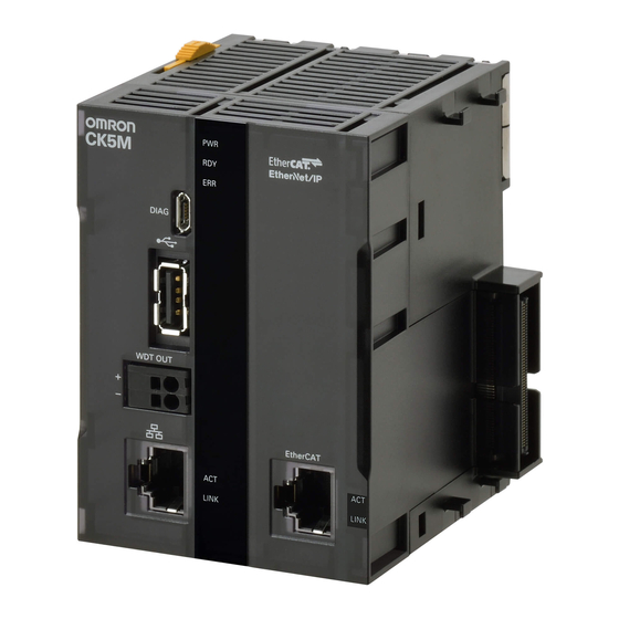
4. Overview This document describes the procedures used to connect the OMRON EtherCAT Remote I/O Terminal model GX- (hereafter referred to as the Slave) using OMRON Programmable Multi-Axis Controller model CK3E-□□□□/CK3M-CPU11/ CK5M-CPU11 (hereafter referred to as the Controller) and EtherCAT, as well as for checking the connection. -
Page 8: Applicable Devices And Device Configuration
This document describes the procedures to establish the network connections. It does not provide information on operations, installations, wiring methods, device functionalities, or device operations, which are not related to the connection procedures. For more information, refer to the manuals or contact your OMRON representative. -
Page 9: Device Configuration
Power PMAC IDE Ver.4.6 Precautions for Correct Use Prepare the ESI file described in this section in advance. Contact your OMRON representative for information on how to procure the ESI file. Precautions for Correct Use Do not share the connection line of EtherCAT communications with other Ethernet networks. -
Page 10: Ethercat Connection Procedure
6. EtherCAT Connection Procedure This section describes the procedure for connecting the Controller with the Slave via EtherCAT. The description assumes that the Controller is set to factory default. 6.1. Workflow Take the following steps to operate the PDO communications via EtherCAT after connecting the Controller with the Slave via EtherCAT. -
Page 11: Preparation For The Controller Setup
6.2. Preparation for the Controller Setup Prepare the Controller settings. Install Power PMAC IDE and Acontis EC-Engineer on the computer in advance. Creation of a New Project Turn on the power to the Controller. Start Power PMAC IDE. * If the dialog for confirming access rights appears upon start-up, select starting of Power PMAC IDE. - Page 12 From the File menu, select New then Project. Enter a project name and location, and select OK.
- Page 13 Initial Settings of the Controller Configure the initial settings for the Controller. Precautions for Correct Use Configuring the initial settings clears all data in the Controller memory. Back up necessary data in advance. In the Terminal tab page, type the $$$*** command to reset the Controller to factory default.
- Page 14 Select Clock Settings. Specify Servo Frequency. Select the Servo Frequency setting from 4 kHz, 2 kHz, or 1 kHz. * Servo Frequency is set to 1 kHz for the example in this document. Click the Accept button. If you have changed the servo frequency setting, type the save command in the Terminal tab page of Power PMAC IDE.
- Page 15 Click Delta Tau – Communication Setupon the toolbar to display the Communication Setupdialog box. In the Device Properties dialog box, click the No Devicebutton. This operation sets the Controller to the offline state. Restart the Controller. The servo frequency that has been set is reflected.
-
Page 16: Installation Of Esi Files
Install the ESI file for the Slave into Power PMAC IDE. Precautions for Correct Use Prepare the ESI file described in this section in advance. Contact your OMRON representative for information on how to procure the ESI file. From the EtherCAT menu of Power PMAC IDE, select ESI Manager. -
Page 17: Ethercat Communications Setup
6.4. EtherCAT Communications Setup Set up EtherCAT communications. Precautions for Correct Use Before taking the following steps, make sure that the devices are connected via an Ethernet cable. If they are not connected, turn OFF the power to the devices, and connect the Ethernet cable. - Page 18 Master0 (Deactivated) is added to Solution Explorer. In the Master tab page, specify a communication period for Cycle Time [us]. * You must specify the communication period in accordance with the servo frequency of the Controller. 1000 us is set in this document. Correspondence between the servo frequencies of the Controller and communication periods is as follows: 4 kHz : 250 us...
- Page 19 Select System – EtherCAT in the Solution Explorer and right-click on Master0 (Deactivated), then select Scan EtherCAT Network. Make sure that the slave is displayed in the Solution Explorer.
- Page 20 Distributed Clock Setup In the Project Explorer, select the target slave GX-ID1611 to display the Advanced Options tab page. In the Advanced Options tab page, clear the Potential Reference Clock check box. In the same manner, clear the Potential Reference Clock check box for GX-OD1611.
- Page 21 PDO Map Settings In the Solution Explorer, select the target slave [Slave_1001[GX-ID1611] ]and display the PDO Mapping tab page. Check Inputs to make sure that only the 258th transmit PDO Mapping 0x1B01 check box is selected.
- Page 22 In the Solution Explorer, select the target slave [Slave_1002[GX-OD1611]] and display the PDO Mapping tab page. Make sure that the check box in the Inputs field is not selected. Make sure that only the 258th receive PDO Mapping 0x1701 check box is selected in the Outputs field.
- Page 23 Creation of an EtherCAT Network Information File Select System – EtherCAT in the Solution Explorer and right-click on Master0 (Deactivated), then select Load Mapping to PowerPMAC. An eni.xml file is added under the Configuration directory in the Solution Explorer. An ECATMap.pmh file is added under the PMAC Script Language/Global Includes directory in the Solution...
-
Page 24: Controller Settings
6.5. Controller Settings EtherCAT Communications Check Take the following steps to ensure that EtherCAT communications are available. From the Terminal tab page, run the ECAT[0].Enable=1 command to start EtherCAT communications. In the Terminal tab page or Watch Window, make sure that the ECAT[0].Enable value turns to 1. - Page 25 Writing the User Program Create programs to be used to check operations. A specific language is used for the operation check programs. Refer to Power PMAC User’s Manual and Power PMAC Software Reference Manual for details. In the Solution Explorer pane, open Project name –...
- Page 26 In the programming area of the pp_startup.txt tab page, add the enable plc 1; program shown on the right to the last line. The pp_startup.txt program is automatically executed when the Controller starts. This example program runs the PLC1 script. Project Data Transfer Transfer the created project data to the Controller.
- Page 27 Downloading a project Right-click the project name in the Solution Explorer pane on the upper right of the IDE screen, and select Build and Download All Programs to run the build and download. * The transferred project is not yet saved to the Controller at this stage.
- Page 28 The program starts running when it has been downloaded successfully. EtherCAT communications are in the OP state. Vary the GX-ID1611 input and make sure that the variable P1001 changes in the Terminal or Watch pane. * If the variable does not change, check that the ECAT[0].Enable value is 1 in the Terminal tab page or Watch...
-
Page 29: Appendix Saving And Loading A Project
7. Appendix Saving and Loading a Project The following describes the procedures to save a Power PMAC IDE project on the computer, and to reuse it. 7.1. Saving a Project Creating a Configuration File Create a Configuration File to save parameters you have changed. - Page 30 Saving a Project In the File menu, run Save All to save the project on the computer.
-
Page 31: Loading And Downloading A Project
7.2. Loading and Downloading a Project Start Power PMAC IDE, and connect to the Controller. In the Terminal tab page, type the $$$*** command to reset the Controller settings to factory default. In the File menu, click Open – Project/Solution to load the project that you saved. - Page 32 Right-click the project name in the Solution Explorer pane, and select Build and Download All Programs to run the build and download. When the download process is complete, make sure that there are no errors in the Output Window. Stopping a program If a program is running, execute the following command from the Terminal tab page to stop the...
- Page 33 Saving the downloaded settings and programs After the download process is complete and you make sure that there are no errors in the Output Window, run the save command from the Terminal tab page. * The save command stores the downloaded project in the Controller.
-
Page 34: Appendix Troubleshooting
8. Appendix Troubleshooting 8.1. Factors Causing EtherCAT Communications To Be Unavailable, and Corrective Actions Description Factor Corrective Action The link is not established. The Ethernet cable is broken or If the Ethernet cable is broken the specified cable is not being or if the specified cable was not used. -
Page 35: How To Check For Errors
8.2. How to Check for Errors Checking the EtherCAT Status You can check the EtherCAT status from Diagnosis Mode of Power PMAC IDE. Right-click on Master0 (Deactivated) under EtherCAT in the Solution Explorer, then select Diagnosis Mode to open the Diagnosis Mode page You can check the status of the slaves in the Diagnosis Mode page. - Page 36 Checking the Controller Status In the Status page of Power PMAC IDE, you can check the status of the motor, coordinate system, and system. To display the Status page, click Status on the toolbar. Global Status You can check system errors such as the WDT error.
- Page 37 Motor Status You can check deviation errors, limit errors, and other states of the motor. Coordinate Status You can check deviation errors, limit errors and other states of the coordinate system.
-
Page 38: Appendix Ecat[I] Structure Elements
9. Appendix ECAT[i] Structure Elements The Controller uses motion controller technology developed by Delta Tau Data Systems, Inc., (hereafter referred to as DT) in the U.S., however, the ECAT[i] structure elements differ from those of DT controllers. The following table shows the major changes that have been made from DT controllers. -
Page 39: Revision History
10. Revision History Revision Revised date Revised content code Apr, 2019 First edition Jan, 2023 ・Made changes accompanying the addition of CK5M-CPU1 □1 Unit. ・Made changes accompanying the modification of GUI of PowerPMAC IDE. - Page 42 Tel: (31) 2356-81-300 Fax: (31) 2356-81-388 Tel: (1) 847-843-7900 Fax: (1) 847-843-7787 ©OMRON Corporation 2019 - 2023 All Rights Reserved. OMRON ASIA PACIFIC PTE. LTD. OMRON (CHINA) CO., LTD. In the interest of product improvement, 438B Alexandra Road, #08-01/02 Alexandra Room 2211, Bank of China Tower, specifications are subject to change without notice.
Need help?
Do you have a question about the CK5M-CPU1 1 Series and is the answer not in the manual?
Questions and answers