Table of Contents
Advertisement
Available languages
Available languages
Quick Links
Operator's Manual
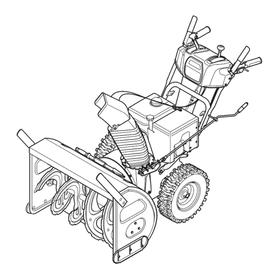
33" SNOW THROWER
Model No. 247.88835
CAUTION: Before using
this product, read this
manual and follow all
safety rules and operating
instructions.
Sears Brands Management Corporation, Hoffman Estates, IL 60179, U.S.A.
Visit our website: www.craftsman.com
• SAFETY
• ASSEMBLY
• OPERATION
• MAINTENANCE
• PARTS LIST
• ESPAÑOL
FORM NO. 769-04980C
6/23/2011
Advertisement
Chapters
Table of Contents

Related Manuals for Craftsman 247.88835


Summary of Contents for Craftsman 247.88835
- Page 1 Operator’s Manual 33” SNOW THROWER Model No. 247.88835 • SAFETY • ASSEMBLY • OPERATION • MAINTENANCE • PARTS LIST CAUTION: Before using • ESPAÑOL this product, read this manual and follow all safety rules and operating instructions. Sears Brands Management Corporation, Hoffman Estates, IL 60179, U.S.A.
-
Page 2: Table Of Contents
This warranty applies for only one year from the date of purchase if this product is ever used while providing commercial services or if rented to another person. For warranty coverage details to obtain free repair or replacement, visit the web site: www.craftsman.com This warranty covers ONLY defects in material and workmanship. Warranty coverage does NOT include: •... -
Page 3: Safe Operation Practices
SAFETY INSTRUCTIONS WARNING DANGER This machine was built to be operated according to the safe opera- This symbol points out important safety instructions which, if not tion practices in this manual. As with any type of power equipment, followed, could endanger the personal safety and/or property of carelessness or error on the part of the operator can result in serious yourself and others. - Page 4 SAFETY INSTRUCTIONS Safe Handling of Gasoline • Exercise extreme caution when operating on or crossing gravel surfaces. Stay alert for hidden hazards or traffic. To avoid personal injury or property damage use extreme care in handling gasoline. Gasoline is extremely flammable and the vapors are •...
- Page 5 SAFETY INSTRUCTIONS MAINTENANCE & STORAGE DO NOT MODIFY ENGINE • Never tamper with safety devices. Check their proper operation To avoid serious injury or death, do not modify engine in any way. regularly. Refer to the maintenance and adjustment sections of Tampering with the governor setting can lead to a runaway engine and this manual.
- Page 6 SAFETY INSTRUCTIONS SAFETY SYMBOLS This page depicts and describes safety symbols that may appear on this product. Read, understand, and follow all instructions on the machine before attempting to assemble and operate. Symbol Description READ THE OPERATOR’S MANUAL(S) Read, understand, and follow all instructions in the manual(s) before attempting to assemble and operate WARNING—...
-
Page 7: Safety Labels
SAFETY LABELS DANGER NEVER PUT HAND IN CHUTE. CONTACT WITH ROTATING PARTS CAN AMPUTATE FINGERS AND HANDS. SHUT OFF ENGINE AND WAIT UNTIL ALL MOVING PARTS HAVE STOPPED BEFORE UNCLOGGING. USE CLEAN-OUT TOOL OR WOODEN STICK TO UNCLOG DISCHARGE CHUTE. -
Page 8: Assembly
ASSEMBLY NOTE: References to right or left side of the snow thrower are determined from the operating position looking forward to the front of the machine. Handle REMOVING FROM CRATE Remove screws from the bottom of the crate securing the sides, and ends of the shipping crate. - Page 9 ASSEMBLY SET-UP Shear Pins A pair of replacement auger shear pins and bow tie cotter pins have been included with your snow thrower. They are stored in the holes provided in the plastic dash panel as seen in Figure 7. For information regarding replacing the shear pins, see Replacing Shear Pins in the Operation section of this manual.
- Page 10 ASSEMBLY Adding Fuel Drift Cutters WARNING The snow thrower drift cutters are mounted inverted at the factory for shipping purposes. Use extreme care when handling gasoline. Gasoline is extremely Remove the four flange nuts (two on each side) and carriage bolts. flammable and the vapors are explosive.
- Page 11 ASSEMBLY To adjust the skid shoes: Adjust skid shoes by loosening the six (three on each side) hex nuts and carriage bolts securing the skid shoes to the auger housing. Refer to Figure 12. While observing the distance between the shave plate and the ground, adjust the skids shoes up or down to achieve the desired shave plate height.
- Page 12 ASSEMBLY Speed Selector Lever Chute Tilt Control Auger Drive Control Control Drive Auger Control Cable Control Cable Rearward most hole of the actuator brackets Figure 13 Figure 14 NOTE: When engaging the auger, you may hear a “chirp” sound. Adjust the lock nut as follows: If adjusting the drive cable, thread This is normal, it is the belt engaging the pulley.
-
Page 13: Operation
(R2) is the faster. IMPORTANT: Do not turn the key in an attempt to start the engine. Doing so may cause it to break. Meets ANSI Safety Standards Craftsman Snow Throwers conform to the safety standard of the American National Standards Institute (ANSI). - Page 14 OPERATION THROTTLE CONTROL AUGER CONTROL The throttle control is located on the rear of the engine. It regulates the speed of the engine and will shut off the engine when moved into the STOP position. PRIMER Pressing the primer forces fuel directly into the engine’s carburetor to aid in starting a “Cold”...
- Page 15 OPERATION TWO-WAY CHUTE-PITCH CONTROL™ CHUTE CLEAN-OUT TOOL The two-way chute-pitch control is located on the left side of the The chute clean-out tool is conveniently fastened to the rear of the handle panel and is used to control the distance of snow discharge auger housing with a mounting clip.
- Page 16 OPERATION Gasoline If you have a grounded three-prong receptacle, proceed as follows. If you do not have the proper house wiring, DO NOT use the electric WARNING starter under any conditions. Use extreme care when handling gasoline. Gasoline is extremely Plug the extension cord into the outlet located on the engine’s flammable and the vapors are explosive.
- Page 17 OPERATION STOPPING THE ENGINE REPLACING SHEAR PINS After you have finished snow-throwing, run engine for a few minutes The augers are secured to the spiral shaft with shear pins and bow-tie before stopping to help dry off any moisture on the engine. cotter pins.
-
Page 18: Service And Maintenance
SERVICE AND MAINTENANCE MAINTENANCE SCHEDULE WARNING Before performing any type of maintenance/service, disengage all Follow the maintenance schedule given below. This chart describes controls and stop the engine. Wait until all moving parts have come to a service guidelines only. Use the Service Log column to keep track of complete stop. - Page 19 SERVICE AND MAINTENANCE WARNING If the engine has been running, the muffler will be very hot. Be careful not to touch the muffler. NOTE: Check the spark plug once a season or every 25 hours of operation. Change the spark plug once a season or every 100 hours. To ensure proper engine operation, the spark plug must be properly gapped and free of deposits.
- Page 20 SERVICE AND MAINTENANCE Wheels After the spark plug is seated, tighten with a spark plug wrench to compress the washer. At least once a season, remove both wheels. Clean and coat the axles with a multipurpose automotive grease before reinstalling wheels. NOTE: When installing a new spark plug, tighten 1⁄2-turn after the Chute Directional Control spark plug seats to compress the washer.
- Page 21 SERVICE AND MAINTENANCE SHAVE PLATE AND SKID SHOES The shave plate and skid shoes on the bottom of the snow thrower are subject to wear. They should be checked periodically and replaced when necessary. Skid Shoes NOTE: The skid shoes on this machine have two wear edges. When one side wears out, they can be rotated 180°...
- Page 22 SERVICE AND MAINTENANCE Wheel drive control Auger Control Refer to the Adjustment section of the Assembly instructions to adjust Refer to the Assembly section for instructions on adjusting the auger the wheel drive control. To further check the adjustment, proceed as control cable.
- Page 23 SERVICE AND MAINTENANCE Loosen the bolt shown in Figure 31 securing the belt keeper bracket and remove the other bolt. Push the belt keeper and bracket up off the engine pulley. Remove Loosen z-fitting Figure 33 Place a block of wood underneath the auger housing as shown in Figure 31 Figure 34 and separate auger housing from the frame by tilting the housing forward and pulling up the handles.
- Page 24 SERVICE AND MAINTENANCE Adapter Post Brake Puck Pulley Slot Figure 35 Figure 36 NOTE: If the pulley adapter was removed with the pulley, align the Roll the drive belt off the lower drive pulley. splines of the pulley adapter and auger input shaft, and push the pulley Remove the belt from the engine pulley.
- Page 25 SERVICE AND MAINTENANCE Using a 3/4” wrench, hold the hex shaft and remove the hex screw and belleville washer and bearing from left side of the frame. Refer to Figure 38. Friction Wheel Ass’y. Remove Hex Screw Belleville Washer Slide Hex Shaft Out Right Side Figure 40...
-
Page 26: Off-Season Storage
OFF-SEASON STORAGE If the snow thrower will not be used for 30 days or longer, or if it is the end of the snow season when the last possibility of snow is gone, the equipment needs to be stored properly. Follow storage instructions below to ensure top performance from the snow thrower for many more years. PREPARING SNOW THROWER PREPARING ENGINE •... -
Page 27: Troubleshooting
TROUBLESHOOTING Problem Cause Remedy Engine fails to start Choke control not in CHOKE position. Move choke control to CHOKE position. Spark plug wire disconnected. Connect wire to spark plug. Faulty spark plug. Clean, adjust gap, or replace. Fuel tank empty or stale fuel. Fill tank with clean, fresh gasoline. -
Page 28: Parts List
PARTS LIST Craftsman Snow Thrower Model 247.88835 43 41... - Page 29 PARTS LIST Craftsman Snow Thrower Model 247.88835 Ref. No. Part No. Description Ref. No. Part No. Description 918-0281A Bracket Assy, Auger Brake 918-04514 Gear Box Assembly, Auger 684-0090B-0637 Impellar, 16” 684-04151-4028 Spiral Assy, LH 931-2643 Tool, Cleanout 684-04152-4028 Spiral Assy, RH 710-0376 Scr,Hex Cap, 5/16-18 x 1.00...
- Page 30 PARTS LIST Craftsman Snow Thrower Model 247.88835 80 13...
- Page 31 PARTS LIST Ref. No. Part No. Description Ref. No. Part No. Description 684-04308A Chute Crank Assembly 731-0903E Lower Chute 684-04350 Joint Block Assembly 731-1313C Chute Tilt Cable Guide 710-0276 Screw, Carriage, 5/16-18 x 1.0 936-0231 Flat Washer 710-04682 Screw, Hex, 3/8-16 x 2.00 Lock, Gr5 784-5594-0637 Cable Bracket 710-0572...
- Page 32 PARTS LIST Craftsman Snow Thrower Model 247.88835 91 95 99 98 93 78 100 86 25 32 47 69 41 12 23 34...
- Page 33 PARTS LIST Craftsman Snow Thrower Model 247.88835 Ref. No. Part No. Description Ref. No. Part No. Description 05244B Housing, Bearing 732-04385 Torsion Spring, .750 I.D. x .968 Lg. 618-0279P Dogg, Steering Drive, LH 936-0158 Washer, Lock, 5/8 618-0280P Dogg, Steering Drive, RH 736-0242 Wsh, Bell., .34 x .872 x .06...
- Page 34 PARTS LIST Craftsman Snow Thrower Model 247.88835 Continued from previous page Ref. No. Part No. Description 710-0157 Screw, Hex Cap, 5/16-24 710-0191 Hex Hd. Screw, 3/8-24 x 1.25 GR8 710-0607 Screw, Hx Wash Hd Tapp 710-0624 Screw, Hex Cap, 5/16-24 x 1.50 710-0654A Screw, 3/8-16 x 1.00...
- Page 35 PARTS LIST Craftsman Snow Thrower Model 247.88835 777S32636 777I22341 777I23013 777S32236 777D13771 777D13770 777I22363 777D13769 777X43688 777I22340 777D11502...
- Page 36 MTD CONSUMER GROUP INC (MTD), the California Air Resources Board (CARB) and the United States Environment Protection Agency (U. S. EPA) Emission Control System Warranty Statement (Owner’s Defect Warranty Rights and Obligations) EMISSION CONTROL SYSTEM COVERAGE IS APPLICABLE TO CERTIFIED ENGINES PURCHASED IN CALIFORNIA IN 2005 AND THERE- AFTER, WHICH ARE USED IN CALIFORNIA, AND TO CERTIFIED MODEL YEAR 2005 AND LATER ENGINES WHICH ARE PURCHASED AND USED ELSEWHERE IN THE UNITED STATES.
- Page 37 (4) Repair or replacement of any warranted part under the warranty provisions of this article must be performed at no charge to the owner at a warranty station. (5) Notwithstanding the provisions of Subsection (4) above, warranty services or repairs must be provided at all MTD distribution centers that are franchised to service the subject engines.
- Page 38 Look For Relevant Emissions Durability Period and Air Index Information On Your Engine Emissions Label Engines that are certified to meet the California Air Resources Board (CARB) Tier 2 Emission Standards must display information regarding the Emissions Durability Period and the Air Index. Sears Brands Management Corporation makes this information available to the consumer on our emission labels.
-
Page 39: Repair Protection Agreement
REPAIR PROTECTION AGREEMENT Congratulations on making a smart purchase. Your new Craftsman® product is designed and manufactured for years of dependable operation. But like all products, it may require repair from time to time. That’s when having a Repair Protection Agreement can save you money and aggravation. -
Page 40: Español
Almacenamiento fuera de temporada ..Página 63 DECLARACIÓN DE GARANTÍA CRAFTSMAN PROFESIONAL DE DOS AÑOS DE GARANTÍA POR DOS AÑOS a partir de la fecha de compra, este producto está garantizado contra cualquier defecto de material o mano de obra. Un producto defectuoso recibirá... -
Page 41: Prácticas Operación Seguras
INSTRUCCIONES DE SEGURIDAD ADVERTENCIA PELIGRO Esta máquina fue construida para ser operada de acuerdo con La presencia de este símbolo indica que se trata de instrucciones las reglas de seguridad contenidas en este manual. Al igual que importantes de seguridad que se deben respetar para evitar con cualquier tipo de equipo motorizado, un descuido o error por poner en peligro su seguridad personal y/o material y la de otras parte del operador puede producir lesiones graves. - Page 42 INSTRUCCIONES DE SEGURIDAD Manejo seguro de la gasolina • Nunca opere la máquina si falta un montaje del canal o si el mismo está dañado. Mantenga todos los dispositivos de seguri- Para evitar lesiones personales o daños materiales tenga mucho dad en su lugar y en funcionamiento.
- Page 43 INSTRUCCIONES DE SEGURIDAD • Para encender el motor, jale de la cuerda lentamente hasta que • Según la Comisión de Seguridad de Productos para el Consu- sienta resistencia, luego jale rápidamente. El repliegue rápido de midor de los Estados Unidos (CPSC) y la Agencia de Protección la cuerda de arranque (tensión de retroceso) le jalará...
- Page 44 INSTRUCCIONES DE SEGURIDAD SÍMBOLOS DE SEGURIDAD Esta página describe los símbolos y figuras de seguridad internacionales que pueden aparecer en este producto. Lea el manual del operador para obtener la información terminada sobre seguridad, reunirse, operación y mantenimiento y reparación. Símbolo Descripción LEA EL MANUAL DEL OPERADOR (S)
-
Page 45: Montaje
MONTAJE NOTA: Las referencias a la derecha oa la izquierda de la nieve Asegure la parte superior e inferior de manejar manejar con las dos lanzador se determinará a partir de la posición de espera de la parte tuercas de mariposa, las arandelas Belleville, pernos y eliminado frontal de la máquina. - Page 46 MONTAJE Soporte tolva Manivela Figura 7 Figura 5 Vuelva a apretar el hardware garantizar la manivela de la tolva Limpieza de soporte. herramientas Compruebe que los cables estén correctamente tolva a través de la guía de cable en la parte superior del motor sudario. Véase la figura 6.
- Page 47 MONTAJE Un indicador de nivel de combustible se encuentra en el depósito de combustible. Llene el depósito de combustible hasta que alcanza el indicador de nivel de combustible, la Figura 10. Tenga cuidado de no en exceso. Indicador de nivel de combustible Vista desde arriba Figura 9...
- Page 48 MONTAJE Baja Shave Plata Fill Shave between Plata high and low marks Alzar Shave Plata Figura 11 Figura 12 AJUSTES BARRENA Y DRIVE CONTROL CABLES Zapatos antideslizantes WARNING La nieve lanzador zapatos antideslizantes se ajustan al alza en la Antes de operar su lanzador nieve, lea cuidadosamente y siga todas las instruc- fábrica para propósitos de envío.
- Page 49 MONTAJE Dejar que la barrena a que mantenga su compromiso de aproximadamente diez (10) segundos antes de soltar el control de barrena. Repita esto varias veces. NOTA: Al realizar la barrena, puede escuchar un “chirp” de sonido. Esto es normal, es el cinturón de la participación de la polea. Como se usa el cinturón, este sonido no se escucha cuando contrate el barrena.
-
Page 50: Operación
IMPORTANTE: No gire la llave en un intento de arrancar el motor. Si lo hace, puede provocar que se rompa. Cumple con ANSI Normas de Seguridad Craftsman Lanzallamas nieve se ajusten a la norma de seguridad de la American National Standards Institute (ANSI) - Page 51 Operación CONTROL DEL ACELERADOR CONTROL DE BARRENA La válvula de control está situado en la parte trasera del motor. Que regula la velocidad del motor y se apagará el motor cuando se trasladó a la posición STOP. PRIMER Al presionar el primer fuerzas combustible directamente en el carburador del motor a la ayuda en el inicio de una “fría”...
- Page 52 Operación BIDIRECCIONAL TOLVA-PITCH CONTROL ™ Parar el motor quitando la llave de contacto. Retire la herramienta de limpieza de la pinza que asegura a la El tobogán de dos vías de paso de control está situado en el lado parte trasera de la vivienda barrena. izquierdo de la palanca del panel y se utiliza para controlar la distancia de la nieve de la tolva de descarga.
- Page 53 Operación • Tenga cuidado de no derramar el combustible, cuando las Conecte el cable de extensión en la toma de corriente situada en el motor de la superficie. Conecte el otro extremo del cable de extensión en un gasolineras. Derrame de combustible o vapor de combustible período de tres patas de 120-voltios, de tierra, toma de CA en una área podría encenderse.
- Page 54 Operación SUSTITUCIÓN DE ROTURA PINES cualquier humedad en el motor. Mover el control del acelerador a la posición STOP. Barrena cada hoja se sujeta al eje de la barrena con una cizalla pines Quitar la llave. La extracción de la clave de reducir la posibilidad y arco-tie clip.
-
Page 55: Servicio Y Mantenimiento
SERVICIO Y MANTENIMIENTO LISTA DE MANTENIMIENTO WARNING Antes de realizar cualquier tipo de mantenimiento / servicio, desactivar Siga la lista de mantenimiento dada abajo. Esta carta describe pautas todos los controles y parar el motor. Espere hasta que todas las piezas de servicio sólo. - Page 56 SERVICIO Y MANTENIMIENTO Control de la bujía Coloque un recipiente adecuado para recolectar el aceite bajo el tapón de drenaje de aceite. ADVERTENCIA Retire el tapón de drenaje de aceite. Vea la Figura 19. NO pruebe la chispa si no está la bujía de encendido. NO dé arranque al motor si no está...
- Page 57 SERVICIO Y MANTENIMIENTO Verifique que la arandela de la bujía esté en buenas condiciones Para retirar la placa de raspado: y enrósquela manualmente para no estropear la rosca. Quite los pernos de carro y las tuercas hexagonales que la Una vez que la bujía esté colocada, apriétela con una llave para sujetan a la caja de la máquina quitanieve.
- Page 58 SERVICIO Y MANTENIMIENTO Si toda la gama de velocidades (adelante y atrás) no se puede lograr, se refieren a la Figura 26 y ajustar el cambio de cable de la siguiente manera: Coloque la palanca de cambios en la posición más rápida la Tuerca hexagonal Cambio de cable Índice Soporte...
- Page 59 SERVICIO Y MANTENIMIENTO para obtener instrucciones. Mueva la palanca de la tolva remoto en el panel de control hacia adelante a la parte superior del pivote tolva hacia abajo, mover la palanca hacia atrás para girar la parte superior de la tolva. De transmisión de la rueda de control Consulte la sección Ajuste de la Asamblea instrucciones para ajustar la rueda de control.
- Page 60 SERVICIO Y MANTENIMIENTO Horquilla clip y arandela Ferrul Figura 33 Barrena Rod polea Bloquear el impulsor con un pedazo de madera para evitar que el hilado y el uso de una 1 / 2 “para quitar la llave hexagonal de Figura 31 tornillo y arandela plana desde el centro de la polea sobre la barrena vivienda.
- Page 61 SERVICIO Y MANTENIMIENTO Coloque la nueva cinta de barrena en la V-ranura de la polea barrena y el lugar de la polea con la correa en el interior del cinturón de mantenimiento. Gire a la polea que sea necesario para alinear sus tres ranuras de aproximadamente con los puestos de la polea del adaptador y, a continuación, gire el soporte de freno de montaje fuera de la ranura de la polea.
- Page 62 SERVICIO Y MANTENIMIENTO Rueda de fricción Asamblea Quite la tuerca hexagonal de tornillo y arandela Belleville Deslice la tuerca hex del eje de salida del lado derecho Eje hexagonal Figura 39 10. Deslice el eje hexagonal a través de la parte derecha de la imagen Figura 37 hacia el lado izquierdo y por el montaje de ruedas de fricción.
-
Page 63: Almacenamiento Fuera De Temporada
ALMACENAMIENTO FUERA DE TEMPORADA Si no se va a utiliza el equipo durante 30 días o más, o si es el final de la temporada de nieve y ya no existe posibilidad de que nieve, es necesario almacenar el equipo de manera adecuada. Siga las instrucciones de almacenamiento que se indican a continuación para garantizar el rendimiento máximo de la máquina quitanieve durante muchos años . -
Page 64: Solución De Problemas
SOLUCIÓN DE PROBLEMAS Problema Causa Remedio El motor no arranca La palanca de obturación no está en la Ponga el interruptor en la posición CHOKE (obtu- posición ON (encendido) ración). Se ha desconectado el cable de la bujía Conecte el cable a la bujía. La bujía no funciona correctamente Limpie, ajuste la distancia disruptiva o cambie. - Page 65 SOLUCIÓN DE PROBLEMAS Problema Causa Remedio Demasiada vibración Hay piezas que están flojas o la barrena Detenga el motor de inmediato y desconecte el está dañada cable de la bujía. Ajuste todos los pernos y las tuercas. Si la vibración continúa, lleve la unidad a reparar a un centro de partes y reparación Sears.
- Page 66 NOTES...
- Page 67 NOTES...
- Page 68 MTD CONSUMER GROUP, INC. (MTD), el Bordo de Recursos de Aire de California (CARB) y la Agencia de Protección Medioambiental de Estados Unidos (U. S. EPA) Declaración de Garantía del Sistema de Control de Emisiones (Derechos y obligaciones del propietario según la garantía contra defectos) LA COBERTURA DE SISTEMA DE CONTROL DE EMISIÓN ES APLICABLE A MOTORES CERTIFICADOS COMPRADOS EN CALIFORNIA EN 2005 Y A PARTIR DE ENTONCES, QUE SON USADOS EN CALIFORNIA, Y HASTA AÑO 2005 DE MODELO CERTIFICADO Y MOTORES POSTERIORES QUE SON COMPRADOS Y USADOS EN OTRA PARTE EN LOS ESTADOS UNIDOS.
- Page 69 reemplazada según la garantía se garantizará por el resto del período de garantía. Cualquier pieza garantizada que esté programada para reemplazo según el mantenimiento requerido de conformidad con las instruc- ciones escritas de la Subsección (c) se garantiza por el período de tiempo anterior a la primera fecha de reemplazo programada para esa pieza.
- Page 70 Busque el período de duración de emisiones importantes yla información de clasificación de aire en la etiqueta de emisiones de su motor Los motores cuyo cumplimiento con los estándares de emisión Tier 2 de la Comisión de Recursos Ambientales de California (CARB) esté...
-
Page 71: Acuerdo De Protección Para Reparaciones
ACUERDO DE PROTECCIÓN PARA REPARACIONES Felicitaciones por haber realizado una adquisición inteligente. El producto Craftsman® que ha adquirido está diseñado y fabricado para brindar muchos años de funcionamiento confiable. Pero como todos los productos a veces puede requerir de reparaciones. Es en ese momento cuando el disponer de un Acuerdo de protección para reparaciones le puede ahorrar dinero y problemas. - Page 72 Get it fixed, at your home or ours! Your Home For troubleshooting, product manuals and expert advice: www.managemylife.com For repair – in your home – of all major brand appliances, lawn and garden equipment, or heating and cooling systems, no matter who made it, no matter who sold it! For the replacement parts, accessories and owner’s manuals that you need to do-it-yourself.
Need help?
Do you have a question about the 247.88835 and is the answer not in the manual?
Questions and answers