Table of Contents
Advertisement
Advertisement
Table of Contents

Related Manuals for Craftsman 247.888500


Summary of Contents for Craftsman 247.888500
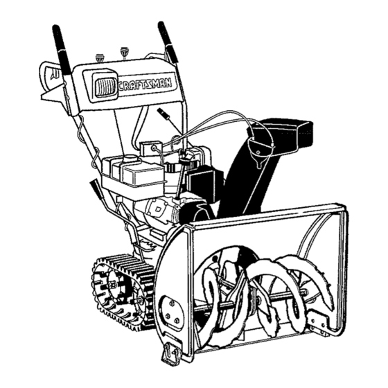
- Page 1 Owner's Manual CRRFTSHRN 8.5 Horse Power 26" Two-Stage Track Drive Snow Thrower CAUTION: Before using this product, read this manual and follow all Safety Rules and Operating Instructions. Sears, Roebuck And Co., Hoffman Estates, IL 60179, U.S.A. Printed in U.S.A. 770-0373A...
- Page 2 Sears will repair, free of charge, any defect in material and workmanship. If this Craftsman snow thrower is used for commercial or rental purposes, this warranty applies for only 30 days from the date of purchase.
-
Page 3: Operation
This symbol points out important safety instructions which, if not followed, could endanger the personal safety and/or property of yourself and others. Read and follow all instructions in this manual before attempting to operate your snow thrower. Failure to comply with these instructions may result in personal injury. -
Page 4: Maintenance And Storage
(such as wheel weights, counter weights, cabs, etc.) approved Following are representations of some of the safety labels on your Craftsman snowthrower. Please follow the instruction on these labels and maintain safety while using or servicing the equipment. - Page 5 These accessories were available when the snow thrower was purchased. They are also available at most Sears retail outlets, catalog and service centers. Most Sears stores can order repair parts for you when you provide the model number of your snow thrower. Belt II I II ..wl...
- Page 6 Lay the hardware pieces from the hardware pack on the figure here and you will have automatically sorted these according to the steps of the assembly procedure described later. (Only one unit of each hardware has been shown per group. The number in parenthesis indicates the total number of the hardware needed in that group.) LookWasher...
-
Page 7: Loose Parts
Traction Drive Handle Rear Control Panel Front Handles Chute Shift Crank Figure I IMPORTANT: This unit is shipped with engine oil, but Chute Crank Assembly without gasoline, in the engine. After assembly, see Shift Rod OPERATION section of this manual for fuel selection Hardware Pack and fill-up. - Page 8 the contour of the carriage bolt head with the thrower using 5/16 x3/4" hex bolt and lock handle. washer from the hardware pack (group A on Attach each side of rear of handle panel with one page 6). Do not tighten at this time. See Figure 2. 1/4-20 hex bolt and flange nut from the hardware Lock Washer&...
-
Page 9: Hairpin
Attaching Shift Rod Place the chute flange keeper (flat side down) beneath lip of chute assembly as shown in Place the shift lever in the sixth (6) speed Figure 6.You will find the chute flange keepers in position. group E of the hardware pack. Place the bent end of the shift rod into the hole in Insert !/4-20 hex bolt from group E of the the shift arm assembly. -
Page 10: Carriage
You may have to loosen the carriage boits and Attaching Turn Triggers hex lock nuts which secure the lower chute crank bracket to the extension on the left side of Check and make sure that the right hand trigger cable is routed in front of the traction drive cable. the chute assembly. -
Page 11: Final Adjustments
hardware p ack. M akesuretoroutethecable tie Adjusting Traction Drive Control overthe drive cable. See Figure 13. ° To check the adjustment of the traction drive control and shift lever, move the weight transfer lever to the transport position (shown in Figure 16 on page 13) and the shift lever all the way forward to sixth (6) position, °... -
Page 12: Knowing Your Snow Thrower
Knowing Your Snow Thrower Read this owner's manual and safety rules before operating your snow thrower. Compare Figure 15 with your snow thrower to familiarize yourself with the location of various controls and adjustments. Save this manual for future reference. The operation of any snow thrower can result in foreign objects being thrown into the eyes, which can result in severe eye damage. -
Page 13: Operating Controls
Chute Distance Control Operating Controls The distance that snow is thrown can be adjusted by (See Figure 15.) adjusting the angle of the chute assembly. Move the chute distance control forward to decrease the Chute Crank distance, toward the rear to increase the distance. The chute crank is located on the left hand side of the Weight Transfer Lever snow thrower. -
Page 14: Before Starting Engine
Before Starting Engine Fill Gas Fuel Cap Plug WARNING: Gasoline is flammable and cau- Spark Plug tion must be used when handling or storing it. Choke Do not fill fuel tank while the snow thrower is running, when it is hot or when it is in an enclosed area. - Page 15 B. Recoil Starter When disconnecting the power cord, always unplug the end from the three-hole, grounded Make sure that the engine has sufficient oit and the receptacle first. auger drive and the traction drive levers are released. Attach spark plug wire to spark plug. •...
-
Page 16: To Throw Snow
according to the depth and condition of snow. Operating Snow Thrower • To turn the unit left, squeeze left trigger; to turn To Engage Drive right, squeeze right trigger. • On each succeeding pass, readjust the chute • With the engine running near top speed, move deflector to the desired position and slightly shift lever to one of six FORWARD positions or overlap the previously cleared path. -
Page 17: General Recommendations
General Recommendations Follow the maintenance schedule given below. Periodically check all fasteners and make sure Always observe safety rules when performing these are tight. any maintenance. The warranty on this snow thrower does not disconnect the spark plug wire before ARNING: Always stop the engine and cover items that have been subjected to operator... -
Page 18: Check V'belts
IMPORTANT: Keep allgrease andoiloffofthe Check V'belts friction wheelandthedriveplate. Follow the instructions below to check the condition Shifting Mechanism of the drive belts every 50 hours of operation. • Lubricate the shifting mechanism and pivot • Remove the plastic belt cover on the front of the points on the shift rod with engine oil at least engine by removing two self-tapping screws. -
Page 19: Engine Maintenance
Engine Maintenance Changing Oil Change engine oil after the first two hours of Engine Oil operation and every 25 hours thereafter. Only use high quality detergent oiI rated with API in order to do that you will have to first drain the spent service classification SF, SG or SH. -
Page 20: Shear
NOTE: If you placed plastic under the gas cap, be WARNING: Always stop the engine, dis- certain to remove it. connect spark plug wire and move it away from the spark plug before performing any Augers adjustments or repairs. The augers are secured to the spiral shaft with two Never attempt to clean the chute or make shear bolts and hex lock nuts. - Page 21 upper hole in the shift lever, Auger Drive Belts • Disconnect the chute crank at the chute Shift Chute Distance assembly by removing the cotter pin and the flat Lever Control Traction washer. Drive • Remove the plastic belt cover on the front of the Auger Clutch engine by removing two self-tapping screws.
- Page 22 offthepulleys. S eeFigure 25. NOTE: The support bracket must rest on the stop bolt afterthe new belt has been assembled. See Figure 26. Front Auger Friction Wheel Rubber Drive Belt The rubber on the friction wheel is subject to wear and should be checked after the first 25 hours of operation and periodically thereafter.
- Page 23 Carburetor with the bell washer and hex bolt. See Figure 28. Sprocket Shift Rod Assembly WARNING: If any adjustments are made to Spacer the engine while the engine is running (e.g. carburetor), keep clear of att moving parts. Bearing Be careful of heated surfaces and muffler. Shaft Washe_ If you think the carburetor needs to be adjusted, see...
-
Page 24: Preparing Engine
Ifyoursnowthrower i sleftunused for30daysor WARNING: Drain fuel into approved longer, it needs to beprepared f orstorage. Also,at container outdoors, away from any open theendofthesnowseason, youshould follow the flame. Be certain engine is cool. Do not samesetofinstructions a ndstorethesnowthrower smoke. properly fortheoff-season. Proper s torage ensures Fuel left inengine during warm weather longer l ifeofthesnowthrower. - Page 25 PROBLEM POSSIBLE CAUSE CORRECTIVE ACTION Shift lever noi locking 1. Shift rod out of adjustment ..i . Remove washer and pin. Turn ferrule into the sixth speed clockwise one turn and reinstall. Engine fails to start 1. Fuel tank empty, or stale fuel, Fill tank with clean, fresh gasoline, 2.
- Page 26 SEARS CRAFTSMAN 8.5 H.P. SNOWTHROWER MODEL 247.885500...
- Page 27 Part No. Qty. Description Part No. Qty. Description 629-0058 736-0i'59 ....Washer 5/6 I.D..684-0008A- Shift Arm Assembly 736-0506 Special Washer 0637 736-0509 Special Washer 684-0022 Chute Crank Assembly 737-0133 Grease 684-0066 Hardware Pack* 741-0475 Plastic Bushing 684-0102 Handle Panel Assembly w/ 746-0896 Chute Deflector Control Cable Tilt...
- Page 29 Part No. Qty, Pa_ No. Description Qty, Description 611-0053 719-0295A! Axle Assembly Track Housing 618-0043 725-0157 Cable Tie Dogg Assembly: R,H. 618-0O44 732-0209 Dogg Assembly: L,H. Extension Spring 618-0169 732-0264 Shift Assembly: Track Drive Extension Spring 683-OO24 736-0105 Berl Washer Hub Assembly: Track Drive 684-0014B _736-0160...
- Page 30 ® ® ® ® ® ®...
- Page 31 Part No. Description Qty, Part No, Qty. Description 750-0547 Spacer 631-0032 wheel Assembly idler 750-0909 Spacer 684-0009 Rod Track Pivot 750-0995 684-0024 Spacer Axle Assembly 784-5639-048_ Plate-Track Side 684-0038 Handle Assembly 784-5642 Plate-Track Lockout 710-0157 Screw 717-1211 710-0459 Screw Gear Ring 717-1209 Gear 12-Tooth 710-0604...
- Page 33 Part No. Part No. Qty. Description Description Qty. 05931 Bearing Housing 731-1379 Chute Adapter 605-5192 Spiral Assembly 732-0611 Extension Spring 605-5193 736-01t9 Lock Washer 5/16 Spiral Assembly 618-0121 Auger Gear Assembly 736-0169 Lock Washer 3/8 684-0040A 736-0174 Spiral Housing Assembly Wave Washer 684-0065 736-0188...
- Page 34 "h Ref, Ref. Part No. Qty. Description Part No. D_esonption ..Qty. Bracket 05896A 736-0331 Washer--Bell 629_0071 Cord, Extension 736-0505 Washer--Flat 710-0117 Screw 748-0234 Shoulder Spacer 710-0157 Screw 748-0360 Pu]Iey, Adapter 710-0230 Screw 754-0346 V-Belt 710-0342 Screw 754-0430 V-Belt Matched 710-0696 Screw 756-0313...
- Page 35 Craftsman Engine Model No. 143.988501 for Craftsman Snow Thrower Model 247.885500 CARBURETOR Part Description Qty. 640052 Carburetor (Incl. 184 of Engine Parts List) 631776# Throttle Shaft & Lever Ass'y 631970 Throttle Return Spring 631778 Throttle Shutter 650506 Shutter Screw 632112 Choke Shaft &...
- Page 36 Craftsman Engine Model No. 143.988501 for Craftsman Snow Thrower Model 247.885500 ,308 03 323 370C...
- Page 37 Craftsman Engine Model No. 143.988501 for Craftsman Snow Thrower Model 247,885500 Part Qty. Description Qty. Description 611093 35385 Flywheel (W/Ring Gear) Cylinder 650880 Bellevilie Washer 27652 Dowel Pin 650881 650820 Screw Flywheel Nut 35135 Oil Drain Extension Solid State Ignition...
- Page 38 Craftsman Engine Model No. 143.988501 for Craftsman Snow Thrower Model 247.885500 Table continued from previous page Part Part Qty. Qty. Description Description Choke Knob 611111 Alternator Coil 35438 323B 611118 Terminal 28820 Screw 29443 650378 Torx Wire Clip Screw, 35392...
- Page 39 Craftsman Engine Model No. 143.988501 for Craftsman Snow Thrower Model 247.885500 Recoil Starter ....Part ..Qty. Description Rewind Starter ..... 59O733 590599A Spring Pin (Incl. 4) Washer 590600 590696 Retainer 590601 Washer 590697 Brake Spring 590698 Starter Dog 590699...
- Page 40 For the repair or replacement parts you need delivered directly to your home Call 7 am - 7 pro, 7 days a week (1-800-366-7278) For in-homemajorbrandrepairservice Call24 hours a day,7 daysa week 1-800-4-REPAIR (1-800-473-7247) Forthe locationof a SearsPartsand RepairCenterin yourarea Call 24 hours a day, 7 days a week 1-800-488-1222 mmmmmm...
Need help?
Do you have a question about the 247.888500 and is the answer not in the manual?
Questions and answers