Table of Contents
Advertisement
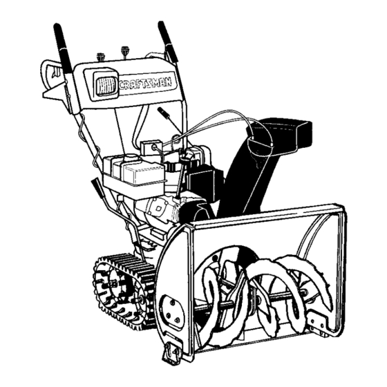
Owner's Manual
/
CRAFTSMAN
9 Horse Power
26" Two-Stage
Track Drive
Snow Thrower
Model No.
247.888510
I!
CAUTION:
Before using this product,
read this manual and follow all Safety
Rules and Operating
Instructions.
Sears, Roebuck
And Co., Hoffman
Estates,
IL 60179, U.S.A.
Form No. 770-10051 B
Printed
in U.S.A.
(9/98)
Advertisement
Table of Contents

Related Manuals for Craftsman 247.88851


Summary of Contents for Craftsman 247.88851
- Page 1 Owner's Manual CRAFTSMAN 9 Horse Power 26" Two-Stage Track Drive Snow Thrower Model No. 247.888510 CAUTION: Before using this product, read this manual and follow all Safety Rules and Operating Instructions. Sears, Roebuck And Co., Hoffman Printed in U.S.A. Estates, IL 60179, U.S.A.
- Page 2 Sears will repair, free of charge, any defect in material and workmanship. If this Craftsman snow thrower is used for commercial or rental purposes, this warranty applies for only 30 days from the date of purchase.
-
Page 3: Operation
This symbol points out important safety instructions which, if not followed, could endanger the personal safety and/or propertyof yourself and others. Read and follow all instructionsin this manual before attempting to operate your snow thrower. Failureto complywith these instructionsmay resultin personal injury.When you see this symbol--heed Your snow thrower was built to be operated according to the rules for safe operation in this manual. -
Page 4: Maintenance And Storage
Use only attachments and accessories (such as wheel weights, counter weights, cabs, etc.) approved Fo ow ng are representations of some of the safety labels on your Craftsman snowthrower. Please follow the instruction on these labels and maintain safety while using or servicing the equipment. - Page 5 Lay the hardware pieces from the hardware pack on the figure here and you will have automatically sorted these according to the steps of the assembly procedure described later. (Only one unit of each hardware has been shown per group. The number in parenthesis indicates the total number of the hardware needed in that group.) Lock Washer HexBolt...
-
Page 6: Removing From Carton
Chute IMPORTANT: This unit is shipped with engine oil, but without gasoline, in the engine. After assembly, see OPERATION section of this manual for fuel selection and fill-up. NOTE: To determine right and left hand sides of your snow thrower, stand behind the unit with the engine farthest away from you. - Page 7 Secure bottom hole on the handle to the snow thrower using 5/16 x3/4" hex bolt and lock washer from the hardware pack (group A on page 5 ). Do not tighten at this time. See Figure 2. Lock Washer & Hex Bolt (1-3/4") Right Handle Handle...
- Page 8 _ook underthisfor i HandlePanel J / ,, Support Chute Crank Bracket Figure 5 You may have to loosen the carriage bolts and hex lock nuts which secure the lower chute crank bracket to the extension on the left side of the chute assembly.
- Page 9 Attaching Clutch Cables The clutch control cables are attached to the snow thrower. If the cables are attached to the top of the engine with cable ties, cut the cable ties now. The Z ends of the clutch cables are hooked into the clutch grips on each handle.
-
Page 10: Final Adjustments
hardware ingroup Hofthehardware pack (on page 5).Pull o nthecable androtate itaround the bottom ofthetrigger, withtheinner c able inthe slot,until t hecable endcanbepushed i ntothe trigger h ousing a ndsnapped tight. S eeFigure 12. Trigger Assembly Inner Cable Barrel Slot Fitting Figure 12 Note: When the cable is installed correctly, it should not be possible to pull cable out of the trigger housing. - Page 11 Recheck t headjustment. Tighten thejamnut against t hecable when correct a djustment is reached. Adjusting Traction Drive Control • To check the adjustment of the traction drive control and shift lever, move the weight transfer lever to the transport position (shown in on ) and the shift lever all the way forward to sixth (6) position.
-
Page 12: Knowing Your Snow Thrower
Knowing Your Snow Thrower Read this owner's manual and safety rules before operating your snow thrower. Compare with your snow thrower to familiarize yourself with the location of various controls and adjustments. Save this manual for future reference. The operation of any snow thrower can result in foreign objects being thrown into the eyes, which can result in severe eye damage. -
Page 13: To Stop Snow Throwe
Operating Controls (See Figure 17.) Chute Crank The chute crank is located on the left hand side of the snow thrower. To change the direction in which snow is thrown, turn chute crank as follows: turn clockwise to discharge to the left; turn counterclockwise to discharge to the right. -
Page 14: Before Starting Engine
Before Starting Engine Fill Gas WARNING: Gasoline is flammable and cau- tion must be used when handling or storing it. Do not fillfuel tank while the snow thrower is running, when it is hot or when it is in an enclosed area. - Page 15 "Final Adjustments" section of the Assembly Instructions. WARNING: The electric starter must be properly grounded at all times to avoid the possibility of elec- tric shock which may be injurious to the operator. • Determine whether your house wiring is a three- wire grounded system.
-
Page 16: To Throw Snow
twoREVERSE p ositions. Select a speed appropriate f orthesnowconditions thatexist. Useslower s peeds until y ouarefamiliar w iththe operation o fthesnow thrower. • Squeeze t hetraction driveclutch gripagainst the right h andle andthesnow thrower w illmove. Release i tandthedrivemotion willstop. To Engage Augers To engage the augers and start snow throwing, squeeze the left hand auger clutch grip against... -
Page 17: Maintenance Schedule
General Recommendations • Always observe safety rules when performing any maintenance. The warranty on this snow thrower does not cover items that have been subjected to operator abuse or negligence. To receive full value from the warranty, operator must maintain the snow thrower as instructed in this manual. -
Page 18: Check V-Belts
Lubrication For a view of the lubrication points on the snow thrower, see Figure 20. Sprocket Shaft Lubricate the sprocket shaft with grease at least once a season or after every 25 hours of operation. IMPORTANT: Keep all grease and oil off of the friction wheel and the drive plate. - Page 19 SAEviscosity g rade according totheexpected operating t emperature. colder .,_32 --._ 5W30 _ Viscosity Chart NOTE: Although multi-viscosity oils (5W30, 10W30 etc.) improve starting in cold weather, these multi- viscosity oils will result in increased oil consumption when used above 32°F. Check your snow thrower's engine oil level more frequently to avoid possible engine damage from running low on oil.
- Page 20 ,& WARNING: Always stop the engine, dis- connect spark plug wire and move it away from the spark plug before performing any adjustments or repairs, Never attempt to clean the chute or make any adjustments while the engine is running. Adjustments Traction Drive Control Refer to the Final Adjustment section of the Set-Up...
- Page 21 Shift Chute Distance Lever Control Drive Clutch Upper Hole Shift Lever Spring Washer Assembly Flat Clip Washer Figure 24 Insert the ferrule into the upper hole in the shift lever from the right side when adjustment is correct. Secure with the flat washer and the hairpin clip that you had earlier removed.
- Page 22 Figure 27 To remove the front auger drive belt, push the idler pulley to the left and lift front auger drive belt from the front auger pulley. See Figure 27. Replace both auger drive belts by following the preceding instructions. NOTE: When reassembling the two halves of the unit, make sure that the auger drive cable is routed through the cable roller guide.
- Page 23 • Reassemble thenewfriction wheel r ubber t o thefriction wheel a ssembly t ightening thesix screws inrotation andwithequal f orce. • Position the friction wheel assembly up onto the pin of the shift rod assembly and slide the shaft through the friction wheel. See Figure 30. •...
-
Page 24: Preparing Engine
ifyoursnow thrower i s leftunused for30daysor longer, i tneeds tobeprepared f orstorage. Also, a t theendofthesnowseason, youshould follow the samesetofinstructions andstore thesnow thrower properly f ortheoff-season. Proper s torage ensures longer l ifeofthesnow thrower. Preparing Engine WARNING: Never store snow thrower with fuel in tank indoors or in poorly ventilated areas, where fuel fumes may reach an open flame, spark or pilot light as on a furnace,... - Page 25 POSSIBLE CAUSE PROBLEM Shift levernot locking 1. Shift rod out of adjustment intothe sixthspeed Enginefailsto start 1. Fuel tank empty, or stale fuel 2. Fuel shut-off valve closed 3. Ignition key not in switch or engine 4. Spark plug wire disconnected 5.
-
Page 26: Parts List
SEARS CRAFTSMAN 9.0 H.P. SNOW THROWER MODEL 247.888510... - Page 27 Pad No. Description 629-0058 Harness for Headlight 684-0008A- Shift Arm Assembly 0637 684-0053 Chute Crank Assembly 684-0066 Hardware Pack* 684-0102 Handle Panel Assembly w/ Tilt 684-0111 Handle Assembly Engagement (LH.) 684-0112 Handle Assembly Engagement (R.H.) 710-0262 Carriage Bolt 5/16-18 x 1.50 710-0442 Hex Bolt 5/16-18 x 1.5 710-0451...
-
Page 28: Snow Thrower
SEARS CRAFTSMAN 9.0 H.P. SNOW THROWER MODEL 247.888510... - Page 29 Part No. Description 611-0053 Axle Assembly 618-0043 Dogg Assembly: R.H, 618-0044 Dogg Assembly: L.H. 618-0169 Shift Assembly: Track Drive 683-0024 Hub Assembly: Track Drive 684-0014B Shift Rod Assembly 684-0021 Friction Wheel Support Bracket Assembly 684-0031 Frame Assembly 684-0042B Friction Wheel Bearing Assembly 710-0643 Hex Lock Screw 5/16-18 x...
- Page 30 SEARS CRAFTSMAN 9.0 H.P. SNOW THROWER MODEL 247.888510 r®...
- Page 31 PaR No. Description 631-0032 Wheel Assembly Idler 684-0009 Rod Track Pivot 684-0024 Axle Assembly 684-0038 Handle Assembly 710-0157 Screw 710-0459 Screw 710-0604 Screw 710-1231 Screw 712-0214 Lock Nut 712-0346 Jam Nut 712-0429 Hex Nut 720-0223 Grip 731-1292 Track 731-1538A Wheel-Track Drive 736-0242 Bell Washer 736-0272...
- Page 32 SEARS CRAFTSMAN 9.0 H.P, SNOW THROWER NOTE: For painted parts, please refer to the listof color codes below. Please add the applicable color code, wherever needed, to the part number to order a replacement part. For instance, if a part,...
- Page 33 Part No. Description 05931 Bearing Housing 605-5192A Spiral Assembly 605-5193A Spiral Assembly 618-0121 Auger Gear Assembly 684-0040A Spiral Housing Assembly 684-0065 Impeller Assembly 705-5226 Chute Reinforcement 710-0703 Carriage Screw 1/4-20 X .75 710-0451 Carriage Bolt 5/16-18 X .75 710-0459A Hex Screw3/8-24 X 1.5 Grade 5 710-0604 Hex Washer Head TT-Screw 5/16-18 X .62...
- Page 34 SEARS CRAFTSMAN 9.0 H.P. SNOW THROWER Ref. Pad No. Description 05896A Bracket 629-0071 Extension Cord Screw 710-0627 710-1245 Screw 710-0230 Screw 710-3005 Screw 710-0696 Screw 710-1652 Screw 712-0181 Jam Nut 731-1324 Belt Cover 732-0710 Spring 736-0119 Fiat Washer 736-O242 Bell Washer...
- Page 35 Craftsman Engine Model No. 143.999005 Snow Thrower Model 247.888510 CARBURETOR _'37 '1_,_37 for Craftsman 640052 631024 632019 631028 631021 ,_,,27 631O22 27136A 27554 640005 632547 640055 27110 630748 631027 Description Qty. Carburetor (Incl. 184 of Engine Parts List) Throttle Shaft & Lever Ass'y.
- Page 36 Craftsman Engine Model No, 143.999005 for Craftsman Snow Thrower Model 247,888510 >300 17 _ 224_ 185. 370C 110A ..- "/ 3"t0G [_370H 285 92_/. _.-..._27...
- Page 37 Craftsman Engine Model No. 143.999005 for Craftsman Snow Thrower Model 247,888510 Part Description 35385 Cylinder Dowel Pin 27652 Screw 650820 Oil Drain Extension 30969 Extension Cap 30699C Governor Rod 30700 Governor Yoke 650494 Screw 33454 Governor Lever 29916 Governor Lever Clamp...
- Page 38 35355 Fuel Cap 35554 Oil Fill Tube 35499 "O" Ring 35540 Fill Tube Clip 36205 Dipstick 650873 Screw 611111 Alternator Coil for Craftsman Part Qty. Description 323B 611118 Terminal 29443 Wire Clip 35392 Starter Plug 35593 Ignition Key 610973 Terminal...
- Page 39 Craftsman Engine Model No. 143.999005 for Craftsman Snow Thrower Model 247,888510 Recoil Starter Recoil Starter (Optional) B--5 Part Description 590733 Rewind Starter 590599A Spring Pin (Incl. 4) 590600 Washer 590696 Retainer 590601 Washer 590697 Brake Spring 590698 Starter Dog 590699...
- Page 40 For the repair or replacement parts you need delivered directly to your home Call 7 am - 7 pm, 7 days a week 1-800-366-PART (1-800-366-7278) For in-home major brand repair service Call 24 hours a day, 7 days a week 1-8OO-4-REPAIR (1-800-473-7247) Forthe locationof a...
Need help?
Do you have a question about the 247.88851 and is the answer not in the manual?
Questions and answers